CN203645556U - Inverter device - Google Patents
Inverter device Download PDFInfo
- Publication number
- CN203645556U CN203645556U CN201320864560.2U CN201320864560U CN203645556U CN 203645556 U CN203645556 U CN 203645556U CN 201320864560 U CN201320864560 U CN 201320864560U CN 203645556 U CN203645556 U CN 203645556U
- Authority
- CN
- China
- Prior art keywords
- cabinet
- direct current
- plate
- filter
- exchanges
- Prior art date
- Legal status (The legal status is an assumption and is not a legal conclusion. Google has not performed a legal analysis and makes no representation as to the accuracy of the status listed.)
- Expired - Lifetime
Links
- RYGMFSIKBFXOCR-UHFFFAOYSA-N Copper Chemical compound [Cu] RYGMFSIKBFXOCR-UHFFFAOYSA-N 0.000 claims abstract description 18
- 229910052802 copper Inorganic materials 0.000 claims abstract description 18
- 239000010949 copper Substances 0.000 claims abstract description 18
- 239000003990 capacitor Substances 0.000 claims abstract description 8
- 230000001681 protective effect Effects 0.000 claims description 6
- 238000001816 cooling Methods 0.000 claims description 5
- 230000005855 radiation Effects 0.000 claims description 3
- 239000000758 substrate Substances 0.000 claims description 3
- 238000012423 maintenance Methods 0.000 abstract description 9
- 230000000712 assembly Effects 0.000 abstract description 6
- 238000000429 assembly Methods 0.000 abstract description 6
- 230000000694 effects Effects 0.000 abstract description 4
- 238000001914 filtration Methods 0.000 abstract 1
- 238000005516 engineering process Methods 0.000 description 3
- 230000004888 barrier function Effects 0.000 description 2
- 230000009286 beneficial effect Effects 0.000 description 1
- 230000007812 deficiency Effects 0.000 description 1
- 238000010586 diagram Methods 0.000 description 1
- 230000005611 electricity Effects 0.000 description 1
- 230000017525 heat dissipation Effects 0.000 description 1
- 238000009434 installation Methods 0.000 description 1
- 238000002955 isolation Methods 0.000 description 1
- 238000004519 manufacturing process Methods 0.000 description 1
- 238000010248 power generation Methods 0.000 description 1
- 239000000126 substance Substances 0.000 description 1
- 239000002699 waste material Substances 0.000 description 1
Images


Abstract
An inversion device belongs to the technical field of power electronics. The inverter device comprises a DC cabinet body, an AC cabinet body and a man-machine interface installed on the DC cabinet body. The inverter device is characterized in that the AC cabinet body and the DC cabinet body are independent respectively, are conjoined through splicing and are electrically connected with each other; DC cabinet door plates are installed at the front and the back of the DC cabinet body; power module assemblies, DC breakers, a DC filter, an LC filtering capacitor and a power source transformer are installed in a cavity of the DC cabinet body; AC cabinet door plates are installed at the front and the back of the AC cabinet body; AC fan assemblies, a power source circuit board, a control circuit board, secondary wire terminals and accessories, an AC breaker, an AC filter and electric reactors are installed in a caviry of the AC cabinet; and input ends of the electric reactors are connected with output sides of the power module assemblies through copper bars. The inverter device has the advantages of small size, reasonable layout, convenient maintenance and disassembly, good electromagnetic compatibility, good protection performance, the excellent heat-radiation effect and the like.
Description
Technical field
The utility model belongs to electric and electronic technical field, is specifically related to a kind of DC-to-AC converter for photovoltaic generating system.
Background technology
In short supply along with the energy, solar energy is as a kind of new forms of energy, and its utilization is more and more universal.Parallel network power generation technology is the important component part that new forms of energy are built, and photovoltaic combining inverter is core devices wherein.In recent years, along with reaching its maturity of photovoltaic combining inverter technology, it is also day by day harsh to the requirement of structural design, and particularly, along with the increase of function, some new assemblies are also employed into.Due to a large amount of uses of non-independent research module, these modules are independent not integrated again separately, cause the production firm of a lot of inverters in the market, in the built-in layout of inverter, there is a lot of unreasonable parts and volume problem bigger than normal, be mainly manifested in the following aspects: 1. heater members is concentrated and piled up, do not optimize distribution, Duct design is unreasonable, causes poor heat radiation; 2. circuit board non-modular designs, the circuit board of several functions disperses to stand in great numbers, disorderly and unsystematic; 3. inverter direct current, AC portion and forceful electric power, weak current part are non-discrete and establish, and mutually intersect, and can produce electromagnetic interference, thereby affect the normal runnability of inverter; 4. the non-modularization design of various parts, the unreasonable grade of structural design makes troubles to maintenance, installation; 5., there is potential safety hazard in safeguard function deficiency; 6. current-sharing poor designs while adopting multiplex circuit input, major loop copper bar moves towards unreasonable, waste material; 7. AC generally adopts contactor to add alternating-current switch mode, causes volume bigger than normal.
In view of above-mentioned prior art, be necessary the topology layout of existing DC-to-AC converter to be improved, technical scheme described below produces under such background.
Summary of the invention
The purpose of this utility model is that the DC-to-AC converter that a kind of volume is little, rationally distributed, repair demolition convenient, Electro Magnetic Compatibility is good, barrier propterty is good, radiating effect is good will be provided.
The purpose of this utility model reaches like this, a kind of DC-to-AC converter, comprise direct current cabinet, exchange cabinet and be arranged on the man-machine interface on direct current cabinet, be characterized in: described interchange cabinet and described direct current cabinet are independent and realize conjunctedly by splicing separately, and both are electrically connected mutually, described direct current cabinet is separately installed with DC cabinet door-plate the forward and backward side of Width, power module assembly, DC circuit breaker, DC filter, LC filter capacitor and power transformer are installed successively in the die cavity of direct current cabinet, described DC circuit breaker connects DC filter by copper bar, described DC filter connects the input side of power module assembly by copper bar, LC filter capacitor and power transformer are separately positioned on the bottom in DC cabinet build chamber, described interchange cabinet is before Width, rear is separately installed with and exchanges cabinet door-plate, in the die cavity that exchanges cabinet, ac fan assembly is installed successively, power supply circuit board, control circuit board, secondary line terminal and annex, AC circuit breaker, alternating current filter and reactor, the input side of described reactor is connected with the outlet side of the power module assembly in direct current cabinet by copper bar, the outlet side of reactor is connected by copper bar with the input side of alternating current filter, the outlet side of alternating current filter is connected by copper bar with the input side of AC circuit breaker, ac fan assembly for reactor heat radiation is arranged on the top that exchanges cabinet die cavity, control circuit board, power supply circuit board is installed on respectively the top that exchanges cabinet die cavity.
In a specific embodiment of the present utility model, described DC cabinet door-plate adopts clamshell doors mode to open.
In another specific embodiment of the present utility model, described DC cabinet door-plate is provided with DC cabinet air inlet, and described direct current cabinet is provided with cooling fan air outlet on the top of short transverse.
In another specific embodiment of the present utility model, described interchange cabinet door-plate is provided with and exchanges cabinet air inlet.
In another specific embodiment of the present utility model, the Rear Door of described interchange cabinet door-plate adopts clamshell doors mode to open.
Also have in a specific embodiment of the present utility model, described AC circuit breaker is installed on the substrate that exchanges cabinet die cavity middle part.
In of the present utility model and then a specific embodiment, described direct current cabinet is provided with protective plate in cabinet at DC cabinet door-plate with the inner side of the front door that exchanges cabinet door-plate respectively with the described cabinet that exchanges.
The utility model, owing to adopting after said structure, has the advantages such as volume is little, rationally distributed, repair demolition convenient, Electro Magnetic Compatibility is good, barrier propterty is good, radiating effect is good.
Accompanying drawing explanation
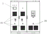
Fig. 1 is the interior front view of the cabinet of DC-to-AC converter of the present utility model.
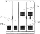
Fig. 2 is the interior rearview of the cabinet of DC-to-AC converter of the present utility model.
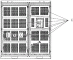
Fig. 3 is the cabinet vertical view of DC-to-AC converter of the present utility model.
Fig. 4 is the cabinet front view of DC-to-AC converter of the present utility model.
Fig. 5 is the cabinet rearview of DC-to-AC converter of the present utility model.
Fig. 6 is the schematic diagram that DC-to-AC converter of the present utility model is provided with protective plate in cabinet.
In figure: 1. direct current cabinet, 11. DC circuit breakers, 12. DC filter, 13. LC filter capacitors, 14. power transformers, 15. power module assemblies, 16. DC cabinet door-plates, 161. DC cabinet air inlets, 17. cooling fan air outlets; 2. interchange cabinet, 21. AC circuit breaker, 22. control circuit boards, 23. power supply circuit boards, 24. reactors, 25. alternating current filters, 26. ac fan assemblies, 27. secondary line terminals exchange cabinet door-plate, 281. and exchange cabinet air inlets with annex, 28.; 3. man-machine interface; 4. protective plate in cabinet.
Embodiment
In order to make the public can fully understand technical spirit of the present utility model and beneficial effect; applicant will describe in detail embodiment of the present utility model below by reference to the accompanying drawings; but applicant is not the restriction to technical scheme to the description of embodiment, anyly changes in the form rather than substance and all should be considered as protection range of the present utility model according to the utility model design.
Refer to Fig. 1, Fig. 2, Fig. 3, Fig. 4, Fig. 5 and Fig. 6, the utility model relates to a kind of DC-to-AC converter, comprise direct current cabinet 1, exchange cabinet 2 and be arranged on the man-machine interface 3 on direct current cabinet 1, described interchange cabinet 2 and described direct current cabinet 1 are independent and realize conjunctedly by splicing separately, and both are electrically connected mutually.
Described direct current cabinet 1 is separately installed with DC cabinet door-plate 16 the forward and backward side of Width, and power module assembly 15, DC circuit breaker 11, DC filter 12, LC filter capacitor 13 and power transformer 14 are installed successively in the die cavity of direct current cabinet 1.The present embodiment preferably adopts two-way DC circuit breaker 11, and two-way DC circuit breaker 11 is connected to DC filter 12 through the consistent copper bar of length, thus the current sharing while having guaranteed multiplex circuit input.DC filter 12 is positioned over the middle part of direct current cabinet 1 die cavity, upwards connects the input side of power module assembly 15 by copper bar.Power module assembly 15 has the advantages such as volume is little, stray inductance is little, good heat dissipation, integral demounting convenience.LC filter capacitor 13 and power transformer 14 are separately positioned on the bottom of direct current cabinet 1 die cavity.Described DC cabinet door-plate 16 all adopts clamshell doors mode to open, and is equipped with air inlet 161.Described direct current cabinet 1 is provided with cooling fan air outlet 17 on the top of short transverse.Air-flow enters in the die cavity of direct current cabinet 1 through eight air inlets 161 that are located on DC cabinet door-plate 16, under the effect of power module assembly 15 blower fans, flow through after the radiator and air channel of power module assembly 15, directly outwards blown out by cooling fan air outlet 17 places on direct current cabinet 1 top.
Described man-machine interface 3 is arranged on the left side door-plate of front door of DC cabinet door-plate 16, shows and user's operation.
Described interchange cabinet 2 is separately installed with and exchanges cabinet door-plate 28 the forward and backward side of Width, in the die cavity that exchanges cabinet 2, ac fan assembly 26, power supply circuit board 23, control circuit board 22, secondary line terminal and annex 27, AC circuit breaker 21, alternating current filter 25 and reactor 24 are installed successively, the input side of described reactor 24 is by the outlet side overlap joint of the power module assembly 15 in copper bar and direct current cabinet 1, and cross cabinet at middle part, saved the length of space and copper bar; The outlet side of described reactor 24 is connected by copper bar with the input side of alternating current filter 25, the outlet side of alternating current filter 25 is connected by copper bar with the input side of AC circuit breaker 21, the top that exchanges cabinet 2 die cavities is provided with the ac fan assembly 26 dispelling the heat for reactor 24, ac fan assembly 26 is screwed in the below that exchanges cabinet 2 roofs, is convenient to dismounting, maintenance. Control circuit board 22,23 points of two circuit boards of power supply circuit board are installed on the metallic plate that exchanges cabinet 2 die cavity tops, have guaranteed the easness of Electro Magnetic Compatibility and maintenance, wiring, strong and weak electricity isolation.The below of control circuit board 22, power supply circuit board 23 is provided with secondary line terminal and annex 27, and secondary wiring terminals and annex 27 are all installed on this, greatly facilitate Maintenance and Repair.Described AC circuit breaker 21 preferably adopts withdrawable AC circuit breaker, be arranged on and exchange on the middle substrate of cabinet 2 die cavities, this AC circuit breaker 21 is under the control of control circuit 22, for realizing grid-connected inverters and cutting off the function of electrical network, due to the characteristic of drawout breaker, its easy maintenance.The Rear Door of described interchange cabinet door-plate 28 adopts door-opening type double swing doors, and on-site maintenance maintenance is convenient, does not need to dismantle door-plate, opens cabinet door and can realize Maintenance and Repair.On described interchange cabinet door-plate 28, be respectively equipped with four and exchange cabinet air inlet 281.
Described direct current cabinet 1 is provided with protective plate 4 in cabinet at DC cabinet door-plate 16 with the inner side of the front door that exchanges cabinet door-plate 28 respectively with the described cabinet 2 that exchanges, and in described cabinet, protective plate 4 is for guaranteeing the electrical security of DC-to-AC converter.
Claims (7)
1.
a kind of DC-to-AC converter, comprise direct current cabinet (1), exchange cabinet (2) and be arranged on the man-machine interface (3) on direct current cabinet (1), it is characterized in that: described interchange cabinet (2) and described direct current cabinet (1) are independent and realize conjunctedly by splicing separately, and both are electrically connected mutually, described direct current cabinet (1) is before Width, rear is separately installed with DC cabinet door-plate (16), power module assembly (15) is installed successively in the die cavity of direct current cabinet (1), DC circuit breaker (11), DC filter (12), LC filter capacitor (13) and power transformer (14), described DC circuit breaker (11) connects DC filter (12) by copper bar, described DC filter (12) connects the input side of power module assembly (15) by copper bar, LC filter capacitor (13) and power transformer (14) are separately positioned on the bottom of direct current cabinet (1) die cavity, described interchange cabinet (2) is before Width, rear is separately installed with and exchanges cabinet door-plate (28), in the die cavity that exchanges cabinet (2), ac fan assembly (26) is installed successively, power supply circuit board (23), control circuit board (22), secondary line terminal and annex (27), AC circuit breaker (21), alternating current filter (25) and reactor (24), the input side of described reactor (24) is connected with the outlet side of the power module assembly (15) in direct current cabinet (1) by copper bar, the outlet side of reactor (24) is connected by copper bar with the input side of alternating current filter (25), the outlet side of alternating current filter (25) is connected by copper bar with the input side of AC circuit breaker (21), ac fan assembly (26) for reactor (24) heat radiation is arranged on the top that exchanges cabinet (2) die cavity, control circuit board (22), power supply circuit board (23) is installed on respectively the top that exchanges cabinet (2) die cavity.
2.
a kind of DC-to-AC converter according to claim 1, is characterized in that described DC cabinet door-plate (16) adopts clamshell doors mode to open.
3.
a kind of DC-to-AC converter according to claim 1, it is characterized in that described DC cabinet door-plate (16) is provided with DC cabinet air inlet (161), described direct current cabinet (1) is provided with cooling fan air outlet (17) on the top of short transverse.
4.
a kind of DC-to-AC converter according to claim 1, is characterized in that described interchange cabinet door-plate (28) is provided with interchange cabinet air inlet (281).
5.
a kind of DC-to-AC converter according to claim 1, is characterized in that the Rear Door of described interchange cabinet door-plate (28) adopts clamshell doors mode to open.
6.
a kind of DC-to-AC converter according to claim 1, is characterized in that described AC circuit breaker (21) is installed on the substrate that exchanges cabinet (2) die cavity middle part.
7.
a kind of DC-to-AC converter according to claim 1, is characterized in that described direct current cabinet (1) is provided with protective plate in cabinet (4) at DC cabinet door-plate (16) with the inner side of the front door that exchanges cabinet door-plate (28) respectively with the described cabinet (2) that exchanges.
Priority Applications (1)
| Application Number | Priority Date | Filing Date | Title |
|---|---|---|---|
| CN201320864560.2U CN203645556U (en) | 2013-12-26 | 2013-12-26 | Inverter device |
Applications Claiming Priority (1)
| Application Number | Priority Date | Filing Date | Title |
|---|---|---|---|
| CN201320864560.2U CN203645556U (en) | 2013-12-26 | 2013-12-26 | Inverter device |
Publications (1)
| Publication Number | Publication Date |
|---|---|
| CN203645556U true CN203645556U (en) | 2014-06-11 |
Family
ID=50876775
Family Applications (1)
| Application Number | Title | Priority Date | Filing Date |
|---|---|---|---|
| CN201320864560.2U Expired - Lifetime CN203645556U (en) | 2013-12-26 | 2013-12-26 | Inverter device |
Country Status (1)
| Country | Link |
|---|---|
| CN (1) | CN203645556U (en) |
Cited By (3)
| Publication number | Priority date | Publication date | Assignee | Title |
|---|---|---|---|---|
| CN104795968A (en) * | 2015-04-03 | 2015-07-22 | 南车株洲电力机车研究所有限公司 | Frequency changer |
| CN105071763A (en) * | 2015-08-06 | 2015-11-18 | 河南森源电气股份有限公司 | Integrated photovoltaic inverter |
| CN107221850A (en) * | 2017-07-18 | 2017-09-29 | 江苏峰谷源储能技术研究院有限公司 | A kind of DC cabinet |
-
2013
- 2013-12-26 CN CN201320864560.2U patent/CN203645556U/en not_active Expired - Lifetime
Cited By (4)
| Publication number | Priority date | Publication date | Assignee | Title |
|---|---|---|---|---|
| CN104795968A (en) * | 2015-04-03 | 2015-07-22 | 南车株洲电力机车研究所有限公司 | Frequency changer |
| CN104795968B (en) * | 2015-04-03 | 2018-09-04 | 南车株洲电力机车研究所有限公司 | Frequency converter |
| CN105071763A (en) * | 2015-08-06 | 2015-11-18 | 河南森源电气股份有限公司 | Integrated photovoltaic inverter |
| CN107221850A (en) * | 2017-07-18 | 2017-09-29 | 江苏峰谷源储能技术研究院有限公司 | A kind of DC cabinet |
Similar Documents
| Publication | Publication Date | Title |
|---|---|---|
| CN201805346U (en) | General current conversion module | |
| CN201750356U (en) | Mounting cabinet for photovoltaic inverter | |
| CN205453514U (en) | Photovoltaic inverter's rack and photovoltaic inverter | |
| CN203883667U (en) | Thyristor self-cooling power module | |
| CN202872614U (en) | High-power water cooling current transformer | |
| CN103441689B (en) | A kind of Modular photovoltaic combining inverter structure | |
| CN203645556U (en) | Inverter device | |
| CN203416177U (en) | Photovoltaic inverter | |
| CN202550293U (en) | Grid-connected cabinet of wind power converter | |
| CN202997950U (en) | Single-phase bridge type inverter based on water cooling | |
| CN201966787U (en) | High-power water-cooling current transformer device | |
| EP2862427A1 (en) | Solar inverter | |
| CN106208728A (en) | A kind of air-cooled power model | |
| CN213521684U (en) | Novel high-power energy storage converter | |
| CN202917839U (en) | Photovoltaic inverter | |
| CN204088904U (en) | A kind of multi-functional photovoltaic exchanges header box | |
| CN202856632U (en) | Photovoltaic grid-connected inverter | |
| CN201846222U (en) | Converter cabinet for wind power generation | |
| CN206041826U (en) | It is high -power from integrative photovoltaic inverter that mixes of net | |
| CN203398978U (en) | Wind power converter with centralized arrangement of major-loop copper bars | |
| CN202385009U (en) | Photovoltaic inverter | |
| CN202014204U (en) | Photovoltaic inverter | |
| CN102082496A (en) | Converter cabinet for wind power generation | |
| CN205029549U (en) | Wind generating set and conversion system thereof | |
| CN212588692U (en) | High-power outdoor photovoltaic inverter structure |
Legal Events
| Date | Code | Title | Description |
|---|---|---|---|
| C14 | Grant of patent or utility model | ||
| GR01 | Patent grant | ||
| CX01 | Expiry of patent term | ||
| CX01 | Expiry of patent term |
Granted publication date: 20140611 |