CN203642115U - Light source plate connector for LED lamp - Google Patents
Light source plate connector for LED lamp Download PDFInfo
- Publication number
- CN203642115U CN203642115U CN201320679550.1U CN201320679550U CN203642115U CN 203642115 U CN203642115 U CN 203642115U CN 201320679550 U CN201320679550 U CN 201320679550U CN 203642115 U CN203642115 U CN 203642115U
- Authority
- CN
- China
- Prior art keywords
- led lamp
- light source
- substrate
- pedestal
- connector
- Prior art date
- Legal status (The legal status is an assumption and is not a legal conclusion. Google has not performed a legal analysis and makes no representation as to the accuracy of the status listed.)
- Withdrawn - After Issue
Links
Images


Abstract
The utility model discloses a light source plate connector for a LED lamp. The light source plate connector comprises two symmetrical C-shaped clamps, wherein the openings of the C-shaped clamps are opposite, and four clamping legs of the two openings form elastic clamps for allowing inserting pins to be inserted to realize electric connection; the side edges of the two C-shaped clamps are downwards connected with base frames, through which, the C-shaped clamps are electrically connected with the light source plates, and the side edges of the two C-shaped clamps are connected with limiting frames upwards to prevent the C-shaped clamps from rolling outwards and deforming. The light source plate connector has a simpler structure, a plastic seat for installation can be saved, and the installation structure is more compact. The light source plate connector can be suitable for manufacturing the LED lamps with different models and sizes, particularly small-sized LED lamps. The range of application is wide, and the light source plate connector is suitable for manufacturing high-power LED lamps.
Description
Technical field
The utility model relates to the technical field of LED lamp, particularly a kind of LED lamp source connector for substrate.
Background technology
In prior art, it is to utilize wire to realize that the power supply of LED lamp connects, and is welded on respectively on light source board and drive plate by the two ends of wire, is embodied as the LED chip power supply on light source board.Very trouble of this electrical connection operation, causes LED lamp assembly cost high, cannot realize automatic assembling.
After have dealer to research and develop various in-line connectors, these direct insertion connections can replace wire to connect, and have simplified the light source board of LED lamp and the electric connection structure of drive plate, attended operation is convenient, assembling processing is more prone to, and can realize automated production.
But existing in-line connector structure is still comparatively complicated, volume is larger, the inadaptable compact LED lamp of manufacturing, and range of application is restricted.
Utility model content
The purpose of this utility model is to provide a kind of LED lamp source connector for substrate, makes its structure simpler, and mounting structure is compacter, is suitable for manufacturing the LED lamp of the model that varies in size, and range of application is wider.
To achieve these goals, the technical solution of the utility model is as follows:
A kind of LED lamp source connector for substrate, comprise two symmetrical C type folders, the opening of C type folder is relative, four pinches of two openings form for pin and insert the elastic clip of realizing electrical connection, the side of two C type folders is connected with pedestal downwards for realizing and being electrically connected with light source board, and the side of two C type folders is upwards connected with position-limited rack and prevents that C type from pressing from both sides the distortion of turning up.
Described position-limited rack in the form of a ring, in be formed centrally through hole and pass for pin.
The side of described each C type folder is each pedestal that connects downwards, and the direct outward of each pedestal forms a welding foot, and whole connector has two welding foots.
The side of described each C type folder is each pedestal that connects downwards, and each pedestal extends to form two welding foots again to two ends, and whole connector has four welding foots.
Described each pedestal extends to two ends and formation two welding foots that bend inwards again.
The lower end of two pinch opposite faces of described C type folder opening forms lead angle.
Described connector bends after by stamped from sheetstock and forms.
Adopt after such scheme, the utility model compared with prior art, utilize pedestal for realizing and being electrically connected with light source board, utilize pedestal to support two symmetrical C type folders, utilize position-limited rack to prevent that two symmetrical C types from pressing from both sides the distortion of turning up, utilizing two symmetrical C type folders to form elastic clip inserts and realizes electrical connection for pin, the utility model structure is simpler, can save to install and use plastic cement seat, mounting structure is compacter, can be suitable for manufacturing the LED lamp of the model that varies in size, particularly compact LED lamp, range of application is wider, and, onesize LED lamp, because of mounting structure of the present utility model compacter, make can arrange more LED light source on power panel, be suitable for manufacturing high-power LED lamp.
Below in conjunction with drawings and the specific embodiments, the utility model is described in further details.
Accompanying drawing explanation
Fig. 1 is the schematic perspective view of the utility model embodiment mono-;
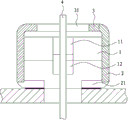
Fig. 2 is that the A of the utility model embodiment mono-is to cutaway view;
Fig. 3 is that the B of the utility model embodiment mono-is to cutaway view;
Fig. 4 is the schematic perspective view of the utility model embodiment bis-.
Label declaration
The specific embodiment
As shown in Figures 1 to 4, be two embodiment of a kind of LED lamp source connector for substrate of the present utility model.
Wherein, a kind of LED lamp source connector for substrate that the embodiment mono-shown in Fig. 1 to Fig. 3 discloses, comprises two symmetrical C type folders 1.The opening of C type folder 1 is relative, and four pinches 11 of two openings form elastic clip, and this elastic clip is that the pin for being connected with drive plate inserts, thereby realizes electrical connection, replaces traditional wire to connect.This elastic clip utilizes the shedding deformation of C type folder 1, four pinches 11 is opened for pin and insert, and utilize the elastic reaction of C type folder 1, makes four pinches 11 hold on to pin, guarantees the stability of electrical connection.Insert for the ease of pin, this embodiment presss from both sides two pinch 11 opposite faces of 1 opening lower end in C type forms lead angle 12.Said pin above, can be the metal ferrule 4 being connected with drive plate or the PEB printed circuit board (PCB) with contact, and printed circuit board (PCB) also can be shaped to one with drive plate.
The side of two C type folders 1 is connected with pedestal 2 downwards, and this pedestal is for realizing and being electrically connected with light source board welding.Fig. 1 presss from both sides side each pedestal 2 that connects downwards of 1 to each C type of embodiment illustrated in fig. 3 one, each pedestal 2 extends to form two welding foots 21 again to two ends, and two welding foots 21 of this embodiment bend inwards, and whole connector has four welding foots 21, Stability Analysis of Structures.
The side of two C type folders 1 is upwards connected with position-limited rack 3, and this position-limited rack 3 connects two C type folders 2 at top, can make to prevent that C type folder 1 from producing the distortion of turning up in the time inserting pin.Position-limited rack 3 can be specifically in the form of a ring, in be formed centrally through hole 31 and pass for pins.Position-limited rack 3 can be also specifically a plate, and the insertion that is applicable to short pin is used.
A kind of LED lamp source connector for substrate that embodiment bis-shown in Fig. 4 discloses, comprises two symmetrical C type folders 1.The side of each C type folder 1 of this embodiment is each pedestal 2 that connects downwards, and the direct outward of each pedestal 2 forms a welding foot 21, and whole connector has two welding foots 21.
From Fig. 1 to Fig. 4, connector construction of the present utility model is simple, can be formed by bending after stamped from sheetstock.This reduces the utility model cost greatly.The utility model can save while installation to install uses plastic cement seat, mounting structure is compacter, can be suitable for manufacturing the LED lamp of the model that varies in size, particularly compact LED lamp, range of application is wider, and, onesize LED lamp, compacter because of mounting structure of the present utility model, make can arrange more LED light source on power panel, be suitable for manufacturing high-power LED lamp.
These are only specific embodiment of the utility model, not the restriction to protection domain of the present utility model.All equivalent variations of doing according to the mentality of designing of this case, all fall into the protection domain of this case.
Claims (7)
1. a LED lamp source connector for substrate, it is characterized in that: comprise two symmetrical C type folders, the opening of C type folder is relative, four pinches of two openings form for pin and insert the elastic clip of realizing electrical connection, the side of two C type folders is connected with downwards for realizing with light source board the pedestal being electrically connected, and the side of two C type folders is upwards connected with and prevents that C type from pressing from both sides the position-limited rack of the distortion of turning up.
2. a kind of LED lamp source connector for substrate as claimed in claim 1, is characterized in that: described position-limited rack in the form of a ring, in be formed centrally the through hole passing for pin.
3. a kind of LED lamp source connector for substrate as claimed in claim 1, is characterized in that: the side of described each C type folder is each pedestal that connects downwards, and the direct outward of each pedestal forms a welding foot, and whole connector has two welding foots.
4. a kind of LED lamp source connector for substrate as claimed in claim 1, is characterized in that: the side of described each C type folder is each pedestal that connects downwards, and each pedestal extends to form two welding foots again to two ends, and whole connector has four welding foots.
5. a kind of LED lamp source connector for substrate as claimed in claim 4, is characterized in that: described each pedestal extends to two ends and formation two welding foots that bend inwards again.
6. a kind of LED lamp source connector for substrate as claimed in claim 1, is characterized in that: the lower end of two pinch opposite faces of described C type folder opening forms lead angle.
7. a kind of LED lamp source connector for substrate as claimed in claim 1, is characterized in that: described connector bends after by stamped from sheetstock and forms.
Priority Applications (1)
| Application Number | Priority Date | Filing Date | Title |
|---|---|---|---|
| CN201320679550.1U CN203642115U (en) | 2013-10-31 | 2013-10-31 | Light source plate connector for LED lamp |
Applications Claiming Priority (1)
| Application Number | Priority Date | Filing Date | Title |
|---|---|---|---|
| CN201320679550.1U CN203642115U (en) | 2013-10-31 | 2013-10-31 | Light source plate connector for LED lamp |
Publications (1)
| Publication Number | Publication Date |
|---|---|
| CN203642115U true CN203642115U (en) | 2014-06-11 |
Family
ID=50873357
Family Applications (1)
| Application Number | Title | Priority Date | Filing Date |
|---|---|---|---|
| CN201320679550.1U Withdrawn - After Issue CN203642115U (en) | 2013-10-31 | 2013-10-31 | Light source plate connector for LED lamp |
Country Status (1)
| Country | Link |
|---|---|
| CN (1) | CN203642115U (en) |
Cited By (2)
| Publication number | Priority date | Publication date | Assignee | Title |
|---|---|---|---|---|
| CN103542388A (en) * | 2013-10-31 | 2014-01-29 | 厦门广泓工贸有限公司 | Light-emitting diode (LED) lamp light source board connector, driving board connecting pin and LED lamp |
| CN108551016A (en) * | 2018-04-02 | 2018-09-18 | 宁波赛锋电子科技有限公司 | A kind of novel conductive piece |
-
2013
- 2013-10-31 CN CN201320679550.1U patent/CN203642115U/en not_active Withdrawn - After Issue
Cited By (3)
| Publication number | Priority date | Publication date | Assignee | Title |
|---|---|---|---|---|
| CN103542388A (en) * | 2013-10-31 | 2014-01-29 | 厦门广泓工贸有限公司 | Light-emitting diode (LED) lamp light source board connector, driving board connecting pin and LED lamp |
| CN108551016A (en) * | 2018-04-02 | 2018-09-18 | 宁波赛锋电子科技有限公司 | A kind of novel conductive piece |
| CN108551016B (en) * | 2018-04-02 | 2020-01-10 | 宁波正翔电子科技有限公司 | Conducting strip |
Similar Documents
| Publication | Publication Date | Title |
|---|---|---|
| CN103542388B (en) | LED light source connector for substrate and driving plate connecting contact pin and LED light | |
| US11149934B2 (en) | LED light apparatus | |
| WO2015139230A1 (en) | Head-hoop type connector and led lamp using same | |
| CN204441542U (en) | A kind of metal connector and apply the LEDbulb lamp of this metal connector | |
| CN204271346U (en) | A kind of harpoon inserting board type connector of improvement | |
| CN105337117A (en) | Wiring terminal | |
| US10069227B2 (en) | Electrical connector device | |
| WO2015139258A1 (en) | Direct-inserting small connector and led lamp using same | |
| CN204103074U (en) | A kind of terminative connector of LED and Male end connector and LED | |
| CN203644985U (en) | Head-hoop-type connector and LED lamp using same | |
| CN203642115U (en) | Light source plate connector for LED lamp | |
| CN204100183U (en) | A kind of simple and easy firm type metal female end and apply the LED of this metal female end | |
| CN2657193Y (en) | Fastening device for radiator | |
| CN203642103U (en) | Simple connector for LED light source plate and LED lamp using connector | |
| CN204205121U (en) | Binding post | |
| CN204100184U (en) | A kind of LED lamp bar being electrically connected female end and applying this electrical connection female end | |
| CN204216264U (en) | The LED of the female small terminal of a kind of straight cutting and male small terminal and correspondence | |
| CN203445272U (en) | Circuit board and socket assembly | |
| CN203868974U (en) | Connector of LED lamp tube, and LED lamp tube with connector | |
| CN205208476U (en) | Drive and light source integral type LED lamp and electric connection structure of light source board and lamp holder thereof | |
| CN201204289Y (en) | Electric connector terminal | |
| CN201478526U (en) | Electrical connector | |
| CN204477969U (en) | The LED of a kind of LED drive plate and light source board connector and application thereof | |
| CN204156146U (en) | A kind of flexible PCB light source strip connector | |
| CN203703876U (en) | Simple side-inserting connector and LED lamp using same |
Legal Events
| Date | Code | Title | Description |
|---|---|---|---|
| C14 | Grant of patent or utility model | ||
| GR01 | Patent grant | ||
| AV01 | Patent right actively abandoned | ||
| AV01 | Patent right actively abandoned |
Granted publication date: 20140611 Effective date of abandoning: 20180619 |