CN203627450U - Fastening connecting assembly for pipes - Google Patents
Fastening connecting assembly for pipes Download PDFInfo
- Publication number
- CN203627450U CN203627450U CN201320817256.2U CN201320817256U CN203627450U CN 203627450 U CN203627450 U CN 203627450U CN 201320817256 U CN201320817256 U CN 201320817256U CN 203627450 U CN203627450 U CN 203627450U
- Authority
- CN
- China
- Prior art keywords
- tubing
- joint
- jackscrew
- plate
- fastenedly connected
- Prior art date
- Legal status (The legal status is an assumption and is not a legal conclusion. Google has not performed a legal analysis and makes no representation as to the accuracy of the status listed.)
- Withdrawn - After Issue
Links
Images


Abstract
The utility model discloses a fastening connecting assembly for pipes. The fastening connecting assembly comprises a joint and a jackscrew. The joint comprises a connecting plate. One end of the connecting plate is bent with a pulling plate and the other end of the connecting plate is bent with a jacking plate tilting towards the interior of the joint. Two sides of the jacking plate are bent with flanging. One end of the jackscrew is threadingly connected to the pulling plate and the other end of the jackscrew abuts against the jacking plate. When the jackscrew is rotated tightly, the pulling plate expands downwardly and the jacking plate expands upwardly and drives the flanging to expand upwardly so that four-surface expansion connection is achieved by the joint and inner walls of the pipes. The fastening connecting assembly is advantaged by being simple in structure, convenient in installation and is capable of effectively improving the fastening strength.
Description
Technical field
The utility model relates generally to the assembling fittings that tubing connects, and relates in particular to a kind of tubing and is fastenedly connected assembly.
Background technique
In prior art, the structure that connects tubing by connection fittings has a variety of, comparatively commonly tubing is inserted after connection fittings, directly tubing and connection fittings are connected and fixed by the fastening piece such as screw, rivet, while adopting said method to connect tubing, installation steps are more numerous and diverse, fastening strength is low, and the stressed of joint mainly concentrates on fastening piece, the force bearing point place of fastening piece is subject to shearing force and fracture failure.
Model utility content
The technical problems to be solved in the utility model is to overcome the deficiencies in the prior art, provides a kind of tubing simple in structure, easy for installation, that can effectively improve fastening strength to be fastenedly connected assembly.
For solving the problems of the technologies described above, the utility model by the following technical solutions:
A kind of tubing is fastenedly connected assembly, comprise joint and jackscrew, described joint comprises connecting plate, described connecting plate one end is bent with arm-tie, and the other end is bent with to the raising plate of joint inner inclination, and described raising plate both sides are bent with flange, described jackscrew one end is threaded with described arm-tie, the other end and raising plate offset, while screwing jackscrew, the downward distending of arm-tie, raising plate upwards distending and drive flange upwards the inwall of distending and tubing form four sides swelling and be connected.
Further improvement as technique scheme:
Described raising plate is provided with pilot hole, and described jackscrew end is provided with described pilot hole and coordinates the frustum offseting.
Described connecting plate is provided with the through hole for connect another outer pipe wall through fastening piece.
Described joint and outer pipe wall joint outer cup are provided with metal finishing cover.
Described metal finishing cover inside is provided with projection, and described connecting plate is provided with the blocked hole that coordinates clamping with projection.
Compared with prior art, the utility model has the advantage of:
Tubing of the present utility model is fastenedly connected assembly, and connecting plate one end is bent with arm-tie, and the other end is bent with to the raising plate of joint inner inclination, raising plate both sides are bent with flange, jackscrew one end is threaded with arm-tie, and the other end and raising plate offset, and it is simple in structure, easy for installation.When assembling, first the connecting plate of joint is connected with the outer wall of a tubing, then another tubing is inserted in to the outside of this joint, with instrument through the perforate of this tubing and screw jackscrew, make the end of jackscrew prop up raising plate, while further screwing jackscrew, arm-tie can downward distending, upwards distending drive upwards distending and form four sides swelling with the inwall of tubing and be connected of flange of raising plate, thereby realize the connection of two tubing, more traditional screw that only passes through, the mode that rivet point connects, on the one hand this structure makes joint and tubing form multiple swellings to be connected, greatly improve fastening strength, on the other hand, in the time that two sections of tubing are damaged power, the power that this connection part bears is not concentrated on jackscrew, but offset by the tension force between joint and pipe material inner wall, thereby can prevent that jackscrew is subject to shearing force and ruptures, avoid the Joint failure of two sections of tubing.
Accompanying drawing explanation
Fig. 1 is the main TV structure schematic diagram that the utility model tubing is fastenedly connected assembly.
Fig. 2 is the A-A sectional structure schematic diagram of Fig. 1.
Fig. 3 is the perspective view that the utility model tubing is fastenedly connected assembly.
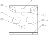
Fig. 4 is the main TV structure schematic diagram that the utility model tubing is fastenedly connected assembly middle joint.
Fig. 5 is the left TV structure schematic diagram that the utility model tubing is fastenedly connected assembly middle joint.
Fig. 6 is the right TV structure schematic diagram that the utility model tubing is fastenedly connected assembly middle joint.
Fig. 7 is the perspective view that the utility model tubing is fastenedly connected assembly middle joint.
In figure, each label represents:
1, joint; 11, connecting plate; 111, through hole; 112, blocked hole; 12, arm-tie; 13, raising plate; 131, flange; 132, pilot hole; 2, jackscrew; 21, frustum; 4, tubing; 5, fastening piece; 6, metal finishing cover; 61, projection; 62, handle hole; 63, dodge hole.
Embodiment
Below with reference to Figure of description and specific embodiment, the utility model is described in further details.
Fig. 1 to Fig. 7 shows the utility model tubing and is fastenedly connected the embodiment of assembly, this connection part comprises joint 1 and jackscrew 2, joint 1 comprises connecting plate 11, connecting plate 11 one end are bent with arm-tie 12, the other end is bent with to the raising plate 13 of joint 1 inner inclination, and raising plate 13 both sides are bent with flange 131, and jackscrew 2 one end are threaded with arm-tie 12, the other end and raising plate 13 offset, and it is simple in structure, easy for installation.When assembling, first the connecting plate of joint 1 11 is connected with the outer wall of a tubing 4, then another tubing 4 is inserted in to the outside of this joint 1, with instrument through the perforate of this tubing 4 and screw jackscrew 2, make the end of jackscrew 2 prop up raising plate 13, while further screwing jackscrew 2, the downward distending of arm-tie 12 meeting, upwards distending drive upwards distending and form four sides swelling with the inwall of tubing 4 and be connected of flange 131 of raising plate 13, thereby realize the connection of two tubing 4, more traditional screw that only passes through, the mode that rivet point connects, on the one hand this structure makes joint 1 and tubing 4 form multiple swellings to be connected, greatly improve fastening strength, on the other hand, in the time that two sections of tubing 4 are damaged power, the power that this connection part bears is not concentrated on jackscrew 2, but offset by the tension force between joint 1 and tubing 4 inwalls, thereby can prevent jackscrew 2 to be subject to shearing force and rupture, avoid the Joint failure of two sections of tubing 4.
In the present embodiment, on raising plate 13, be further provided with pilot hole 132, jackscrew 2 ends are provided with and coordinate the frustum 21 offseting with pilot hole 132, answer frustum 21 to be arranged in pilot hole 132, guarantee in the time screwing jackscrew 2, the skew of can not sliding on raising plate 13 of these jackscrew 2 ends, thus concentrating of power guaranteed, be conducive to swelling and connect effect.
In the present embodiment, connecting plate 11 is provided with the through hole 111 for connect another tubing 4 outer walls through fastening piece 5, and this through hole 111 can be connected whole joint 1 through connecting plate 11 fastening piece 5 with another tubing 4 outer walls, guaranteed connection effect.
In the present embodiment, joint 1 is provided with metal finishing cover 6 with tubing 4 outer wall joint outer cup, metal finishing overlaps 6 inside and is provided with projection 61, connecting plate 11 is provided with the blocked hole 112 that coordinates clamping with projection 61, by the cooperation clamping of this projection 61 and blocked hole 112, guarantee the connective stability of metal finishing cover 6 with joint 1.
In the present embodiment, further offer the handle hole 62 for stretching into instrument rotation jackscrew 2 on metal finishing cover 6, also offer and dodge hole 63 for what dodge fastening piece 5, this metal finishing cover 6 can play and beautify outward appearance and certain seal action.
Although the utility model discloses as above with preferred embodiment, but not in order to limit the utility model.Any those of ordinary skill in the art, in the situation that not departing from technical solutions of the utility model scope, all can utilize the technology contents of above-mentioned announcement to make many possible variations and modification to technical solutions of the utility model, or be revised as the equivalent embodiment of equivalent variations.Therefore, every content that does not depart from technical solutions of the utility model,, all should drop in the scope of technical solutions of the utility model protection any simple modification made for any of the above embodiments, equivalent variations and modification according to the utility model technical spirit.
Claims (7)
1. a tubing is fastenedly connected assembly, comprise joint (1) and jackscrew (2), it is characterized in that: described joint (1) comprises connecting plate (11), described connecting plate (11) one end is bent with arm-tie (12), the other end is bent with to the raising plate (13) of joint (1) inner inclination, described raising plate (13) both sides are bent with flange (131), described jackscrew (2) one end is threaded with described arm-tie (12), the other end and raising plate (13) offset, while screwing jackscrew (2), arm-tie (12) is distending downwards, raising plate (13) upwards distending and drive flange (131) upwards the inwall of distending and tubing (4) form four sides swelling and be connected.
2. tubing according to claim 1 is fastenedly connected assembly, it is characterized in that: described raising plate (13) is provided with pilot hole (132), and described jackscrew (2) end is provided with and coordinates the frustum (21) offseting with described pilot hole (132).
3. tubing according to claim 1 and 2 is fastenedly connected assembly, it is characterized in that: described connecting plate (11) is provided with the through hole (111) for connect another tubing (4) outer wall through fastening piece (5).
4. tubing according to claim 1 and 2 is fastenedly connected assembly, it is characterized in that: described joint (1) is provided with metal finishing cover (6) with tubing (4) outer wall joint outer cup.
5. tubing according to claim 4 is fastenedly connected assembly, it is characterized in that: described metal finishing cover (6) inside is provided with projection (61), and described connecting plate (11) is provided with the blocked hole (112) that coordinates clamping with projection (61).
6. tubing according to claim 3 is fastenedly connected assembly, it is characterized in that: described joint (1) is provided with metal finishing cover (6) with tubing (4) outer wall joint outer cup.
7. tubing according to claim 6 is fastenedly connected assembly, it is characterized in that: described metal finishing cover (6) inside is provided with projection (61), and described connecting plate (11) is provided with the blocked hole (112) that coordinates clamping with projection (61).
Priority Applications (1)
| Application Number | Priority Date | Filing Date | Title |
|---|---|---|---|
| CN201320817256.2U CN203627450U (en) | 2013-12-13 | 2013-12-13 | Fastening connecting assembly for pipes |
Applications Claiming Priority (1)
| Application Number | Priority Date | Filing Date | Title |
|---|---|---|---|
| CN201320817256.2U CN203627450U (en) | 2013-12-13 | 2013-12-13 | Fastening connecting assembly for pipes |
Publications (1)
| Publication Number | Publication Date |
|---|---|
| CN203627450U true CN203627450U (en) | 2014-06-04 |
Family
ID=50813933
Family Applications (1)
| Application Number | Title | Priority Date | Filing Date |
|---|---|---|---|
| CN201320817256.2U Withdrawn - After Issue CN203627450U (en) | 2013-12-13 | 2013-12-13 | Fastening connecting assembly for pipes |
Country Status (1)
| Country | Link |
|---|---|
| CN (1) | CN203627450U (en) |
Cited By (1)
| Publication number | Priority date | Publication date | Assignee | Title |
|---|---|---|---|---|
| CN103711761A (en) * | 2013-12-13 | 2014-04-09 | 湖南省金为型材有限公司 | Pipe fastening connection assembly |
-
2013
- 2013-12-13 CN CN201320817256.2U patent/CN203627450U/en not_active Withdrawn - After Issue
Cited By (2)
| Publication number | Priority date | Publication date | Assignee | Title |
|---|---|---|---|---|
| CN103711761A (en) * | 2013-12-13 | 2014-04-09 | 湖南省金为型材有限公司 | Pipe fastening connection assembly |
| CN103711761B (en) * | 2013-12-13 | 2016-08-24 | 湖南省金为型材有限公司 | Tubing is fastenedly connected assembly |
Similar Documents
| Publication | Publication Date | Title |
|---|---|---|
| CN203627450U (en) | Fastening connecting assembly for pipes | |
| CN204060026U (en) | A kind of bracing frame for building | |
| CN203230686U (en) | Tube fixing and connecting part | |
| CN103216504B (en) | For the expansion type connecting piece that tubing connects | |
| CN203463439U (en) | Fastening and connecting part for pipe with pre-punching hole | |
| CN203373971U (en) | Foldable embedded sleeve device | |
| CN103711761A (en) | Pipe fastening connection assembly | |
| CN105064825B (en) | Fast disassembly type hinge for detachable sash | |
| CN203702769U (en) | Guardrail | |
| CN203702768U (en) | Guard bar allowing surface pipe and stand column to be tightly connected | |
| CN201344176Y (en) | Connection block device | |
| CN204598784U (en) | Flower case corner structure | |
| CN203230689U (en) | Expansion-type connecting member used for pipe connection | |
| CN203700993U (en) | Assembled guard bar | |
| CN204868721U (en) | Punching press assembly devices | |
| CN204061460U (en) | A kind of fixed structure having Line Doorbell | |
| CN203584224U (en) | Exposed head corner connector | |
| CN204059772U (en) | Roof longitudinal expansion joint coupling assembling | |
| CN103557214B (en) | Tubing is with being fastenedly connected assembly | |
| CN203560228U (en) | Fitting for fastening connection of pipes provided with preset holes | |
| CN203516319U (en) | Connecting component used for being connected with surface tube | |
| CN204591051U (en) | Double-layer air-permeable window | |
| CN204059750U (en) | Mounting rail structure | |
| CN203626225U (en) | Structure for connecting scaffold with wall | |
| CN203701475U (en) | Guard bar with face pipe and stand column in expansion connection |
Legal Events
| Date | Code | Title | Description |
|---|---|---|---|
| C14 | Grant of patent or utility model | ||
| GR01 | Patent grant | ||
| AV01 | Patent right actively abandoned |
Granted publication date: 20140604 Effective date of abandoning: 20160824 |
|
| C25 | Abandonment of patent right or utility model to avoid double patenting |