CN203617766U - Portable power source - Google Patents
Portable power source Download PDFInfo
- Publication number
- CN203617766U CN203617766U CN201320686193.1U CN201320686193U CN203617766U CN 203617766 U CN203617766 U CN 203617766U CN 201320686193 U CN201320686193 U CN 201320686193U CN 203617766 U CN203617766 U CN 203617766U
- Authority
- CN
- China
- Prior art keywords
- power source
- portable power
- electromagnetic wave
- induction panel
- transmitting coil
- Prior art date
- Legal status (The legal status is an assumption and is not a legal conclusion. Google has not performed a legal analysis and makes no representation as to the accuracy of the status listed.)
- Expired - Fee Related
Links
Images
Landscapes
- Charge And Discharge Circuits For Batteries Or The Like (AREA)
Abstract
The utility model provides a portable power source including a rubber shell. A sensing panel is arranged in the rubber shell. A charging switch, an indicating lamp and a USB charging socket is arranged on a side face of the sensing panel. A voltage-reducing rectifying circuit and an electromagnetic wave transmitting circuit are arranged in the sensing panel. The USB charging socket is connected with two input terminals of the voltage-reducing rectifying circuit. Two output terminals of the voltage-reducing rectifying circuit are connected with two input terminals of the electromagnetic wave transmitting circuit. An output terminal of the electromagnetic wave transmitting circuit is connected with a transmitting coil. A receiving coil is arranged inside an electric device to be charged. An output terminal of the receiving coil is connected with a battery of the electric device. The transmitting coil is connected with the charging switch. The indicating lamp is connected with the charging switch, the transmitting coil and the USB charging socket. The portable power source provided by the utility model is simple in structure and small in size and can storage electricity as well as charge the electric device. Besides, the electric device can be fixed at a special position relatively in a charging process, so that convenience, quickness and safety are ensured.
Description
Technical field
The utility model relates to a kind of portable power source, belongs to power technique fields.
Background technology
Portable power source is a kind of portable charger that integrates power supply and charge function, can charge whenever and wherever possible or standby power supply to digital equipments such as mobile phones.Generally by lithium cell or dry cell as charge storage unit.Whether the discharging current when core technology of portable power source is to charge the phone and the curve of voltage be level and smooth, and this is to be personally related to the important technology index that whether can damage charging device, and this discharge curve test must be seen third-party authoritative examining report.The quality of portable power source depends primarily on battery core and baffle two aspects.Certainly, portable power source is not disposable apparatus, and it is more than can Reusability hundreds of times.So also must there be charging management system portable power source inside.Charging management system can, according to the voltage of lithium electricity, regulate charging current automatically.
The portable power source that has now many moneys on market, is suitable for each electronic product.But having a very important drawback is exactly being connected between portable power source and electronic equipment only to only have a data wire.Bring unnecessary trouble will to so charging anywhere or anytime.For example, between power supply and electronic equipment, line is too much wound around, because first electronic equipment is not fixed, electronic equipment produces loose contact phenomenon etc. because jolt.
Utility model content
It can accumulate can be also electronic equipment induction charging that the technical problems to be solved in the utility model is to provide one, and the portable power source of energy stationary electronic devices relative position.
In order to solve the problems of the technologies described above, the technical solution of the utility model is to provide a kind of portable power source, it is characterized in that: comprise rubbery outer cover, rubbery outer cover inside is provided with induction panel, and induction panel side is provided with charge switch, indicator light and USB charging socket; When charging, electronic equipment to be charged is located on the induction panel in rubbery outer cover;
Induction panel inside is provided with a step-down rectifying circuit and an electromagnetic wave radiating circuit, USB charging socket is connected with two inputs of step-down rectifying circuit, two outputs of step-down rectifying circuit are connected with two inputs of electromagnetic wave radiating circuit, and the output of electromagnetic wave radiating circuit connects transmitting coil; Receiving coil is located at electronic equipment inner side to be charged, and receiving coil output is connected with electric device battery; Transmitting coil connects charge switch, and indicator light connects charge switch, transmitting coil and USB charging socket.
Preferably, the outside of described transmitting coil is provided with rubber plastics-insulated layer.
Preferably, the size of described rubbery outer cover can just secure the above electronic equipment to be charged.
The using method of the portable power source that the utility model provides is: while charging for induction panel, usb data line one end is connected to computer, the other end inserts the USB charging socket on induction panel, and indicator light is bright, and is red, now shows that induction panel is in charging.Bright when indicator light, and while being green light, induction panel has been filled electric weight.Mobile phone is placed on induction panel, is placed in rubbery outer cover, now, mobile phone will produce induced current and prepare charging between preparation and induction panel, and rubbery outer cover is relatively fixing by it.Then flicking charge switch, induction panel will start charging for mobile phone.Now indicator light is bright, and is red.Now the storing electrical energy in induction panel will produce magnetic field by transmitting coil, thereby make the receiving coil in mobile phone also produce magnetic field, thereby be converted into electric energy, from the output of receiving coil output, enter battery of mobile phone, play the effect of wireless charging.When induction panel is that after mobile phone is full of electricity, indicator light is bright, and it is green light.
The device that the utility model provides has overcome the deficiencies in the prior art, simple in structure, volume is light and handy, not only can charge on computers with data wire, and can utilize induction generation current between electronic equipment and then be electronic equipment charging, more can be in charging the position of relative stationary electronic devices, thereby convenient when consumer is used, quick, use safer.
Accompanying drawing explanation
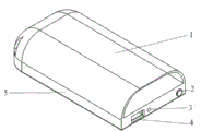
The portable power source schematic perspective view that Fig. 1 provides for the utility model;
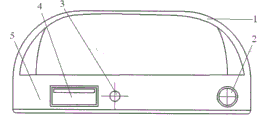
The portable power source end view that Fig. 2 provides for the utility model.
Embodiment
For the utility model is become apparent, hereby with a preferred embodiment, and coordinate accompanying drawing to be described in detail below.
Fig. 1 and Fig. 2 are respectively portable power source schematic perspective view and the end view that the utility model provides, described portable power source comprises rubbery outer cover 1, rubbery outer cover 1 inside is provided with induction panel 5, and induction panel 5 sides are provided with charge switch 2, indicator light 3 and USB charging socket 4.Rubbery outer cover 1 is similar to phone housing but is more bigger than it, thus the relative position between fixing mobile phone and portable power source.
The using method of the portable power source that the utility model provides is: while charging for induction panel, usb data line one end is connected to computer, and the other end inserts the USB charging socket 4 on induction panel 5, and indicator light is bright, and be red, now show that induction panel 5 is in charging.Bright when indicator light 3, and while being green light, oneself is filled electric weight induction panel 5.Mobile phone is placed on induction panel 5, is placed in rubbery outer cover 1, now, mobile phone will produce induced current and prepare charging between preparation and induction panel 5, and rubbery outer cover 1 is relatively fixing by it.Then flicking charge switch 2, induction panel 5 will start charging for mobile phone.Now indicator light 3 is bright, and is red.Now the storing electrical energy in induction panel 5 will produce magnetic field by transmitting coil, thereby make the receiving coil in mobile phone also produce magnetic field, thereby be converted into electric energy, from the output of receiving coil output, enter battery of mobile phone, play the effect of wireless charging.After induction panel 5 is full of electricity for mobile phone, indicator light 3 is bright, and is green light.
Using method when portable power source is miscellaneous equipment charging and cell phone type are seemingly.
The device that the utility model provides has overcome the deficiencies in the prior art, simple in structure, volume is light and handy, not only can charge on computers with data wire, and can utilize induction generation current between electronic equipment and then be electronic equipment charging, more can be in charging the position of relative stationary electronic devices, thereby convenient when consumer is used, quick, use safer.
Claims (3)
1. a portable power source, it is characterized in that: comprise rubbery outer cover (1), rubbery outer cover (1) inside is provided with induction panel (5), and induction panel (5) side is provided with charge switch (2), indicator light (3) and USB charging socket (4); When charging, it is upper that electronic equipment to be charged is located at the interior induction panel (5) of rubbery outer cover (1):
Induction panel (5) inside is provided with a step-down rectifying circuit and an electromagnetic wave radiating circuit, USB charging socket (4) is connected with two inputs of step-down rectifying circuit, two outputs of step-down rectifying circuit are connected with two inputs of electromagnetic wave radiating circuit, and the output of electromagnetic wave radiating circuit connects transmitting coil; Receiving coil is located at electronic equipment inner side to be charged, and receiving coil output is connected with electric device battery; Transmitting coil connects charge switch (2), and indicator light (3) connects charge switch (2), transmitting coil and USB charging socket (4).
2. a kind of portable power source as claimed in claim 1, is characterized in that: the outside of described transmitting coil is provided with rubber plastics-insulated layer.
3. a kind of portable power source as claimed in claim 1, is characterized in that: the size of described rubbery outer cover (1) can just secure the above electronic equipment to be charged.
Priority Applications (1)
| Application Number | Priority Date | Filing Date | Title |
|---|---|---|---|
| CN201320686193.1U CN203617766U (en) | 2013-11-01 | 2013-11-01 | Portable power source |
Applications Claiming Priority (1)
| Application Number | Priority Date | Filing Date | Title |
|---|---|---|---|
| CN201320686193.1U CN203617766U (en) | 2013-11-01 | 2013-11-01 | Portable power source |
Publications (1)
| Publication Number | Publication Date |
|---|---|
| CN203617766U true CN203617766U (en) | 2014-05-28 |
Family
ID=50770388
Family Applications (1)
| Application Number | Title | Priority Date | Filing Date |
|---|---|---|---|
| CN201320686193.1U Expired - Fee Related CN203617766U (en) | 2013-11-01 | 2013-11-01 | Portable power source |
Country Status (1)
| Country | Link |
|---|---|
| CN (1) | CN203617766U (en) |
Cited By (3)
| Publication number | Priority date | Publication date | Assignee | Title |
|---|---|---|---|---|
| CN105356538A (en) * | 2015-11-19 | 2016-02-24 | 天长市地震办公室 | Portable mobile power supply |
| CN105391123A (en) * | 2015-11-19 | 2016-03-09 | 天长市地震办公室 | Silicon rubber case type mobile power supply with loudspeaker |
| CN109217490A (en) * | 2018-09-18 | 2019-01-15 | 国网江苏省电力有限公司盐城供电分公司 | A kind of wireless mobile power supply and its charging/discharging thereof |
-
2013
- 2013-11-01 CN CN201320686193.1U patent/CN203617766U/en not_active Expired - Fee Related
Cited By (4)
| Publication number | Priority date | Publication date | Assignee | Title |
|---|---|---|---|---|
| CN105356538A (en) * | 2015-11-19 | 2016-02-24 | 天长市地震办公室 | Portable mobile power supply |
| CN105391123A (en) * | 2015-11-19 | 2016-03-09 | 天长市地震办公室 | Silicon rubber case type mobile power supply with loudspeaker |
| CN109217490A (en) * | 2018-09-18 | 2019-01-15 | 国网江苏省电力有限公司盐城供电分公司 | A kind of wireless mobile power supply and its charging/discharging thereof |
| CN109217490B (en) * | 2018-09-18 | 2024-04-05 | 国网江苏省电力有限公司盐城供电分公司 | Wireless mobile power supply and charging and discharging method thereof |
Similar Documents
| Publication | Publication Date | Title |
|---|---|---|
| CN202424278U (en) | Multi-purpose charger | |
| CN203119520U (en) | Nfc charging device | |
| CN203617766U (en) | Portable power source | |
| CN202474952U (en) | Replaceable intelligent battery charger with leather sheath | |
| CN102983375A (en) | Wireless chargeable lithium battery | |
| CN204030206U (en) | A kind of Multifunctional data line with emergent charging apparatus | |
| CN204012788U (en) | Portable integrated portable power source | |
| CN203800657U (en) | Mobile power supply with expansible cell grooves | |
| CN206894306U (en) | A kind of multi-functional more mouthfuls of USB chargers | |
| CN105720674A (en) | Solar collection-based mobile power source | |
| CN202906506U (en) | Movable power supply capable of functioning as charger | |
| CN104917256A (en) | Solar wireless charging mobile power supply | |
| CN103872740A (en) | Mobile power source with battery core groove extensible | |
| CN204706930U (en) | A kind of solar-electricity wireless charging portable power source | |
| CN102761143A (en) | Portable mobile phone charger | |
| CN204361764U (en) | Intelligent charger | |
| CN209169980U (en) | It is a kind of to charge to multiple mobile power sources and cradle with wireless charging function | |
| CN202840555U (en) | Mobile terminal of power supply device thereof | |
| CN204947660U (en) | Lithium battery group state monitoring device | |
| CN202977651U (en) | Wireless rechargeable lithium battery | |
| CN205319763U (en) | Take charger of electric power storage ability | |
| CN104659845A (en) | Adaptive battery charger | |
| CN204205688U (en) | A kind of charger with switch | |
| CN204706932U (en) | To power stable wireless mobile power supply | |
| CN202888883U (en) | Electronic device and shell thereof |
Legal Events
| Date | Code | Title | Description |
|---|---|---|---|
| C14 | Grant of patent or utility model | ||
| GR01 | Patent grant | ||
| CF01 | Termination of patent right due to non-payment of annual fee | ||
| CF01 | Termination of patent right due to non-payment of annual fee |
Granted publication date: 20140528 Termination date: 20161101 |