CN203594740U - Rear transmission box of tractor - Google Patents
Rear transmission box of tractor Download PDFInfo
- Publication number
- CN203594740U CN203594740U CN201320691855.4U CN201320691855U CN203594740U CN 203594740 U CN203594740 U CN 203594740U CN 201320691855 U CN201320691855 U CN 201320691855U CN 203594740 U CN203594740 U CN 203594740U
- Authority
- CN
- China
- Prior art keywords
- main shaft
- bevel gear
- clutch cover
- tractor
- casing
- Prior art date
- Legal status (The legal status is an assumption and is not a legal conclusion. Google has not performed a legal analysis and makes no representation as to the accuracy of the status listed.)
- Expired - Lifetime
Links
- 230000005540 biological transmission Effects 0.000 title claims abstract description 20
- RYGMFSIKBFXOCR-UHFFFAOYSA-N Copper Chemical compound [Cu] RYGMFSIKBFXOCR-UHFFFAOYSA-N 0.000 claims description 16
- 229910052802 copper Inorganic materials 0.000 claims description 14
- 239000010949 copper Substances 0.000 claims description 14
- 210000004124 hock Anatomy 0.000 claims description 6
- 125000006850 spacer group Chemical group 0.000 claims description 3
- NJPPVKZQTLUDBO-UHFFFAOYSA-N novaluron Chemical compound C1=C(Cl)C(OC(F)(F)C(OC(F)(F)F)F)=CC=C1NC(=O)NC(=O)C1=C(F)C=CC=C1F NJPPVKZQTLUDBO-UHFFFAOYSA-N 0.000 abstract 1
- 238000000034 method Methods 0.000 description 3
Images
Abstract
The utility model discloses a rear transmission box of a tractor. A main shaft is arranged in a box body of the transmission box, a spline groove is formed in the main shaft, the main shaft is arranged on the two side walls of the box body through bearings, the box body is arranged at the rear end of a tractor gearbox, a clutch sleeve, a drive bevel gear and a power input part are arranged on the main shaft, a groove is formed in the clutch sleeve, an output bevel gear shaft and a clutch sleeve deflector rod are arranged on the rear portion of the box body, the output bevel gear shaft is movably arranged in a bearing pedestal, a bevel gear disc at the front end of the output bevel gear shaft stretches into the box body and is meshed with the drive bevel gear, the clutch sleeve deflector rod is arranged in a fixing base, and a round head at the front end of the clutch sleeve deflector rod stretches into the groove of the clutch sleeve in the box body. According to the technology, power output by the rear end of the tractor gearbox is introduced into the rear transmission box through the power input part, and transmitted to a rear wheel drive system through the rear transmission box, and four-wheel drive of the tractor can be achieved.
Description
Technical field
The utility model belongs to tractor transmission case technical field, relates to the rear transmission case of a kind of east wind 12 hand tractors and variant motor truck thereof.
Background technique
In prior art, the gear box bottom of east wind 12 hand tractors and variant motor truck thereof is provided with a driving front case, and the effect of driving front case is to drive front-wheel to rotate.Along with the development of technology, east wind 12 hand tractors and variant motor truck thereof need to, to the future development of four-wheel drive, be realized the object of this type of tractor four-wheel drive, need to solve the problem to its trailing wheel transferring power.At present, on some large-scale tractors, realized four-wheel drive, but due to the particularity of east wind 12 hand tractors and variant motor truck gearbox designs thereof, after existing tractor, transmission case technology can not be applied in this type of tractor.
Summary of the invention
The utility model is in prior art, east wind 12 hand tractors and variant motor truck thereof lack rear transmission case technology, can not realize the problem of four-wheel drive, transmission case after a kind of tractor is provided, in the casing of this transmission case, main shaft is installed, on main shaft, be processed with spline, bearing for spindle is arranged on the two side of casing, casing is arranged on the rear end of gear box of tractor, on its main shaft, clutch cover is installed, bevel gear and power input component, on clutch cover, be processed with groove, the driving lever of conical tooth shaft and clutch cover is installed at casing rear portion, conical tooth shaft is movably arranged in axle bed, the cone fluted disc of conical tooth shaft front end stretches in casing and engages with bevel gear, driving lever is arranged in fixed base, the round end of its front end stretches in the groove of clutch cover in casing.
Adopt technique scheme, transmission case after the power of exporting on gear box of tractor can being introduced by power input component, band dynamic bevel gear, by being connected or disconnection of clutch sleeve control power input component and bevel gear, drive conical tooth shaft by bevel gear, conical tooth shaft rear wheel drive system drives trailing wheel to rotate, and realizes the four-wheel drive of tractor.
Technique scheme has two preferred versions, one is that power input component is designed to an input gear, be arranged between clutch cover and bevel gear, clutch cover is connected with main spindle multiple spline with bevel gear, input gear one side assembling jump ring, opposite side dress spacer, between input gear and main shaft, sliding sleeve is installed, in clutch cover one side design plush copper, at input gear one side design recess, recess is connected with plush copper hock.In this programme, when the transmission of power of gearbox is on input gear time, owing to sliding sleeve being installed between input gear and main shaft, input gear dallies on the sliding sleeve of main shaft, when driving lever is stirred clutch cover, when plush copper on clutch cover is inserted the recess of input gear one side, input gear drives clutch cover to rotate, and clutch cover drives main shaft to rotate, and main shaft band dynamic bevel gear rotates, bevel gear drives conical tooth shaft to rotate, and conical tooth shaft drives the rear wheel drive system work of tractor.
Another preferred version is that power input component is designed to sprocket wheel, the spindle nose of main shaft stretches out outside casing, sprocket wheel is arranged on the spindle nose of main shaft, bevel gear is arranged on clutch cover side, and both sides are fixed with jump ring, is designed with plush copper in clutch cover one side, be designed with recess in bevel gear one side, recess is connected with plush copper hock, and clutch cover is connected with main spindle multiple spline, between bevel gear and main shaft, sliding sleeve is installed.Adopt this programme, the power of gearbox transmission can be delivered on main shaft by sprocket wheel, drives main shaft to rotate, because clutch cover is connected with main spindle multiple spline, clutch cover rotates with main shaft, owing to sliding sleeve being installed between bevel gear and main shaft, main shaft dallies in the sliding sleeve of bevel gear, when driving lever is stirred clutch cover, when the plush copper of clutch cover one side is inserted the recess of bevel gear one side, clutch cover band dynamic bevel gear rotates, and bevel gear drives conical tooth shaft to rotate, and conical tooth shaft drives the rear wheel drive system work of tractor.
Accompanying drawing explanation
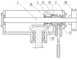
Fig. 1 is the utility model embodiment one cross-sectional view.
Fig. 2 is the utility model embodiment two cross-sectional view.
Embodiment
Embodiment one: as shown in Figure 1, transmission case after a kind of tractor, in its casing 2, main shaft 3 is installed, on main shaft 3, be processed with spline 4, main shaft 3 use bearings 1 are arranged on the two side of casing 2, this casing 2 is arranged on the rear end of gear box of tractor, clutch cover 11 is installed on main shaft 3, bevel gear 5 and power input component, on clutch cover 11, be processed with groove 12, at casing 2 rear portions, conical tooth shaft 17 and clutch cover driving lever 15 are installed, conical tooth shaft 17 is movably arranged in axle bed 18, the cone fluted disc 19 of its front end stretches in casing 2 and engages with bevel gear 5, clutch cover driving lever 15 is arranged in fixed base 14, the round end 13 of its front end stretches in the groove 12 of clutch cover in casing,
Power input component is an input gear 8, be arranged between clutch cover 11 and bevel gear 5, clutch cover 11 and bevel gear 5 and main shaft 3 spline joints, input gear 8 one sides are equipped with jump ring 16, opposite side is equipped with spacer 6, between input gear 8 and main shaft 3, sliding sleeve 7 is installed, and is designed with plush copper 10 in clutch cover 11 1 sides, be designed with recess 9 in input gear 8 one sides, recess 9 is connected with plush copper 10 hocks.
Embodiment two: as shown in Figure 2, transmission case after a kind of tractor, its structure is basic identical with embodiment one, difference is: power input component is sprocket wheel 20, the spindle nose of main shaft 3 stretches out outside casing 2, sprocket wheel 20 is arranged on the spindle nose of main shaft 3, bevel gear 5 is arranged on clutch cover 11 sides, both sides are fixing with jump ring 16, be designed with plush copper 10 in clutch cover 11 1 sides, be designed with recess 21 in bevel gear one side, recess 21 is connected with plush copper 10 hocks, clutch cover 11 and main shaft 3 spline joints, be provided with sliding sleeve 22 between bevel gear 5 and main shaft 3.
Claims (3)
1. transmission case after tractor, main shaft (3) is installed in its casing (2), on main shaft (3), be processed with spline (4), main shaft (3) is arranged on the two side of casing (2) with bearing (1), it is characterized in that: this casing (2) is arranged on the rear end of gear box of tractor, clutch cover (11) is installed on main shaft (3), bevel gear (5) and power input component, on clutch cover (11), be processed with groove (12), the driving lever (15) of conical tooth shaft (17) and clutch cover is installed at casing (2) rear portion, conical tooth shaft (17) is movably arranged in axle bed (18), the cone fluted disc (19) of conical tooth shaft (17) front end stretches in casing (2) and engages with bevel gear (5), driving lever (15) is arranged in fixed base (14), the round end (13) of its front end stretches in the groove (12) of clutch cover in casing.
2. transmission case after tractor as claimed in claim 1, it is characterized in that: power input component is an input gear (8), be arranged between clutch cover (11) and bevel gear (5), clutch cover (11) and bevel gear (5) and main shaft (3) spline joint, input gear (8) one sides are equipped with jump ring (16), opposite side is equipped with spacer (6), between input gear (8) and main shaft (3), sliding sleeve (7) is installed, be designed with plush copper (10) in clutch cover (11) one sides, be designed with recess (9) in input gear (8) one sides, recess (9) is connected with plush copper (10) hock.
3. transmission case after tractor as claimed in claim 1, it is characterized in that: power input component is sprocket wheel (20), the spindle nose of main shaft (3) stretches out outside casing (2), sprocket wheel (20) is arranged on the spindle nose of main shaft (3), bevel gear (5) is arranged on clutch cover (11) side, jump ring for both sides (16) is fixing, be designed with plush copper (10) in clutch cover (11) one sides, be designed with recess (21) in bevel gear one side, recess (21) is connected with plush copper (10) hock, clutch cover (11) and main shaft (3) spline joint, between bevel gear (5) and main shaft (3), sliding sleeve (22) is installed.
Priority Applications (1)
| Application Number | Priority Date | Filing Date | Title |
|---|---|---|---|
| CN201320691855.4U CN203594740U (en) | 2013-11-05 | 2013-11-05 | Rear transmission box of tractor |
Applications Claiming Priority (1)
| Application Number | Priority Date | Filing Date | Title |
|---|---|---|---|
| CN201320691855.4U CN203594740U (en) | 2013-11-05 | 2013-11-05 | Rear transmission box of tractor |
Publications (1)
| Publication Number | Publication Date |
|---|---|
| CN203594740U true CN203594740U (en) | 2014-05-14 |
Family
ID=50675633
Family Applications (1)
| Application Number | Title | Priority Date | Filing Date |
|---|---|---|---|
| CN201320691855.4U Expired - Lifetime CN203594740U (en) | 2013-11-05 | 2013-11-05 | Rear transmission box of tractor |
Country Status (1)
| Country | Link |
|---|---|
| CN (1) | CN203594740U (en) |
Cited By (2)
| Publication number | Priority date | Publication date | Assignee | Title |
|---|---|---|---|---|
| CN104033544A (en) * | 2014-06-05 | 2014-09-10 | 安徽天时插秧机制造有限公司 | Gearbox assembly of walking rice transplanter |
| CN107950101A (en) * | 2017-12-15 | 2018-04-24 | 中国农业大学 | A kind of straw scattering draught, which turns over, buries combine |
-
2013
- 2013-11-05 CN CN201320691855.4U patent/CN203594740U/en not_active Expired - Lifetime
Cited By (3)
| Publication number | Priority date | Publication date | Assignee | Title |
|---|---|---|---|---|
| CN104033544A (en) * | 2014-06-05 | 2014-09-10 | 安徽天时插秧机制造有限公司 | Gearbox assembly of walking rice transplanter |
| CN104033544B (en) * | 2014-06-05 | 2017-12-15 | 安徽天时插秧机制造有限公司 | A kind of gearbox assembly of hand transplanting machine |
| CN107950101A (en) * | 2017-12-15 | 2018-04-24 | 中国农业大学 | A kind of straw scattering draught, which turns over, buries combine |
Similar Documents
| Publication | Publication Date | Title |
|---|---|---|
| CN203580944U (en) | Motor suspension device of bogie of eight-axle electric locomotive | |
| CN203460923U (en) | Steering mechanism | |
| CN203594740U (en) | Rear transmission box of tractor | |
| CN203995525U (en) | Amph four-wheel drive mechanism | |
| CN202026614U (en) | Novel wheel type self-walking harvester gear box | |
| CN203962756U (en) | Transmission shaft | |
| CN203666388U (en) | Inspection robot and walking mechanism of inspection robot | |
| CN203766410U (en) | Steering drive axle | |
| CN204164273U (en) | The gear-box of multi-output shaft | |
| CN205853880U (en) | Farmland pesticide spraying vehicle front wheel drive system | |
| CN201137675Y (en) | Dual-purpose drive gearbox for automobile wheel transmission and external connection mechanical drive | |
| CN203962663U (en) | A kind of industrial robot transmission shaft | |
| CN203592896U (en) | Gear transmission full-driving tractor chassis | |
| CN203703024U (en) | Speed change gear box | |
| CN203369090U (en) | Power transmission mechanism for sprinkling machine | |
| CN203126523U (en) | Power driving system for forklift | |
| CN203353082U (en) | Simple and easy connector for tilling box and walking box of banking machine | |
| CN202790453U (en) | Meshing sleeve of power output shaft | |
| CN206633815U (en) | Compound transmission with propons differential lock and two-axis transfer case apparatus | |
| CN204020571U (en) | The power take-off implement of trac. | |
| CN205226242U (en) | Planet transmission structure | |
| CN202790452U (en) | Transmission mechanism of power output shaft for gearbox of tractor | |
| CN203594750U (en) | Tractor gearbox with lateral transmission box | |
| CN208153688U (en) | Wheeled tractor transfer case | |
| CN204127276U (en) | The linkage structure of ransaxle ring gear and knuckle |
Legal Events
| Date | Code | Title | Description |
|---|---|---|---|
| C14 | Grant of patent or utility model | ||
| GR01 | Patent grant | ||
| CX01 | Expiry of patent term | ||
| CX01 | Expiry of patent term |
Granted publication date: 20140514 |