CN203586057U - Double-head solar LED spotlight - Google Patents
Double-head solar LED spotlight Download PDFInfo
- Publication number
- CN203586057U CN203586057U CN201320740569.2U CN201320740569U CN203586057U CN 203586057 U CN203586057 U CN 203586057U CN 201320740569 U CN201320740569 U CN 201320740569U CN 203586057 U CN203586057 U CN 203586057U
- Authority
- CN
- China
- Prior art keywords
- lamp body
- lamp
- base
- light
- solar led
- Prior art date
- Legal status (The legal status is an assumption and is not a legal conclusion. Google has not performed a legal analysis and makes no representation as to the accuracy of the status listed.)
- Expired - Fee Related
Links
Images


Landscapes
- Arrangement Of Elements, Cooling, Sealing, Or The Like Of Lighting Devices (AREA)
Abstract
The utility model relates to a double-head solar LED spotlight. The double-head solar LED spotlight comprises lamp holders and a base. The double-head solar LED spotlight is characterized in that each lamp holder comprises a lamp body, a rotating part, a light transmitting part, a reflection cover and an LED light-emitting plate, and a battery is installed in the base; the reflection cover and the LED light-emitting plate are installed in the lamp body, and the reflection cover is located on the front face of the LED light-emitting plate; the LED light-emitting plate is tightly attached to the lamp body, and a heat dissipation structure is arranged on the lamp body; the light transmitting part covers an opening in the front face of the lamp body; the rotating part is respectively connected with the lamp body and the base movably. An integral reflection disk is adopted for the double-head solar LED spotlight, the light effect is good, and the double-head solar LED spotlight is more delicate and beautiful in appearance; a hang-out solar panel assembly is high in power, the light effect of the whole spotlight is good, the base and the lamp holders are delicate and small, and the heat dissipating effect is good; the two lamp holders are horizontally arranged left and right, the lamp bodies can vertically and horizontally rotate in a three-dimensional mode, the light projection direction is flexible to adjust, and the illumination range and the application range are wider.
Description
Technical field
The utility model relates to a kind of double end solar LED shot-light, is mainly used in being arranged on the wall of outdoor buildings, belongs to a kind of lighting.
Background technology
In prior art, conventional LED Solar lamp generally adopts low-power LED, luminous plaque, reflection shield, and the weld that can also directly see electric wire and LED having, from the appearance gets up more ugly.Solar components is directly installed on lamp holder, and power is little, and luminous efficiency is low, and whole lamp is heavier; Lamp holder can not rotate, and light projector direction can not be adjusted on demand.
Utility model content
The purpose of this utility model is to overcome above shortcomings in prior art, and a kind of reasonable in design, volume is little, light efficiency good, light projector direction is adjustable, illumination range is wide double end solar LED shot-light are provided.
The technical scheme in the invention for solving the above technical problem is: this double end solar LED shot-light comprises lamp body, turns part, transmission element, reflector and LED luminous plaque, in described base, battery is installed; Described reflector and LED luminous plaque are arranged in lamp body, described reflector be positioned at LED luminous plaque before; Described LED luminous plaque is close to lamp body, has radiator structure on lamp body; Described transmission element covers the opening before lamp body; The described part that turns is flexibly connected with lamp body and base respectively.Lamp body can rotate relative to turning part in the vertical direction, and turning part can rotate in the horizontal direction relative to base, and lamp body entirety can be relative to base vertically and level is three-dimensional rotates, and light projector direction can be adjusted as required, uses flexible, conveniently; Turn part position limiting structure can be set, prevent ovdersteering, avoid wire intertwist; Reflection shield does as a whole optical reflective disk, and surface is preferably pure white, and reflecting effect is good, and can block inner electric wire and solder joint, makes outward appearance seem more attractive in appearance; Solar components is not set directly on lamp holder or base, but is equipped with plug-in solar panels assembly, adopts external mode, makes lamp body and base exquisiter small and exquisite, and plug-in solar panels assembly power is large, makes the luminous efficiency of lamp high.
Base described in the utility model comprises hanging feet, base plate and hanging feet plate, and base plate is arranged on below hanging feet, hanging feet board enter hanging feet after; Described battery is placed in the interior corresponding groove of hanging feet; The described part that turns is flexibly connected with hanging feet.The whole lamp of the chargeable energy supply of battery is arranged on metope by hanging feet plate.
The front openings surrounding of lamp body described in the utility model is provided with gum box, has glue in gum box, and transmission element is fixed by glue and lamp body.Glue fixing seal performance is good, can effectively prevent that outside rainwater from entering in head, has improved the security performance in use procedure.
Described in the utility model turning between part and lamp body is provided with and turns to sealing ring.By turning to the frictional force of sealing ring can make lamp body locate better, and can enter lamp body by effectively anti-sealing.
Below base described in the utility model, inductor is installed.Inductor can be responded to opening and closing light, more energy-conservation.
Inductor described in the utility model is movably connected in below base plate, and the both sides limited location structure of base plate.Inductor is rotatable and spacing by position limiting structure, can within the scope of 270 degree, rotate, and inductor induction range extensively and again can prevent ovdersteering, avoids wire intertwist.
On reflector described in the utility model, be provided with locating dowel, this locating dowel snaps in corresponding hole on LED luminous plaque, and reflector is connected with LED luminous plaque.Reflection shield, also can be located without screw by locating dowel and the pore structure of mutually mating with LED luminous plaque, is convenient to installing/dismounting.
Lamp holder described in the utility model has identical two of structure, and two lamp holder equal altitudes levels left and right arrange.Lamp holder level left and right arranges two, and illumination range is wider.
The utility model compared with prior art, has the following advantages and effect: adopt overall reflective dish, light efficiency is good, and outward appearance is more exquisite attractive in appearance; Plug-in solar panels assembly power is large, and whole light is imitated, and base and lamp holder exquisiteness is small and exquisite, good heat dissipation effect; About lamp holder level arranges two, and lamp body can vertical and horizontal stereo rotating, and the adjustment of light projector direction is flexible, and illumination range is wider, widely applicable.
Accompanying drawing explanation
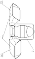
Fig. 1 is the main TV structure schematic diagram of the utility model embodiment.
Fig. 2 is the left TV structure schematic diagram of the utility model embodiment.
Fig. 3 is the decomposition texture schematic diagram of the utility model embodiment.
In figure: lamp holder 1, base 2, lamp body 11, turn part 12, transmission element 13, reflector 14, LED luminous plaque 15, turn to sealing ring 16, hanging feet 21, base plate 22, inductor 23, hanging feet plate 24, battery 25, right lamp holder 101, left lamp holder 102.
The specific embodiment
Below in conjunction with accompanying drawing and by embodiment, the utility model is described in further detail.
Embodiment.
Referring to Fig. 1-Fig. 3, the present embodiment comprises lamp holder 1 and base 2, lamp holder 1 comprises lamp body 11, turns part 12, transmission element 13, reflector 14, LED luminous plaque 15 and turn to sealing ring 16, and base 2 comprises hanging feet 21, base plate 22, inductor 23, hanging feet plate 24, battery 25; Lamp holder 1 has two, and the structure that is respectively right lamp holder 101 and 102, two lamp holders 1 of left lamp holder is identical; Transmission element 13 is transparent material making.
In the present embodiment, LED luminous plaque 15 is fixed in lamp body 17 and fits with lamp body 11, on lamp body 11, be provided with radiator structure, the radiator structure that passes through lamp body 11 of LED luminous plaque 15 dispels the heat, this radiator structure is radiating ribs structure, heat dispersion is good, has extended service life, has improved overall security performance; On reflector 14, have locating dowel, the locating dowel of reflector 14 snaps on LED luminous plaque 15 corresponding hole, make reflector 14 be positioned at LED luminous plaque 15 before, then by transmission element 13, reflector 14 is pressed in lamp body 11; The front openings surrounding of lamp body 17 is provided with gum box, plays glue in gum box, transmission element 13 cover opening above of lamp body 11 and by glue with fixing, can effectively prevent that outside rainwater from entering in head, improved the security performance in use procedure; Turn part 12 and adopt screw to be connected with the bottom of lamp body 11, lamp body 11 can rotate (preferably within the scope of 90 degree) in vertical direction relative to turning part 12; Turn to be provided with between part 12 and lamp body 11 and turn to sealing ring 16, tighten the screws can make lamp body 11 relatively turn part 12 to locate, turn to that sealing ring 16 is compacted reaches sealing simultaneously, can effectively anti-sealing enter and utilize frictional force that lamp body 11 is located better.
In the present embodiment, turn part 12 and be flexibly connected with hanging feet 21, turn part 12 relatively hanging feet 21 horizontally rotate; Base plate 22 is arranged on below hanging feet 21; On base plate 22, be provided with through hole, on inductor 23, be provided with boss, the through hole that the boss of inductor 23 snaps in base plate 22 is movably connected in inductor 23 below base plate 22, and inductor 23 relatively base plate 22 horizontally rotates, preferably within the scope of 270 degree; The both sides limited location structure of base plate 22, can limit inductor 23 and excessively rotate, and prevents that electric wire from damaging; Battery 25 is placed in the interior corresponding groove of hanging feet 21; Hanging feet plate 24 snap in hanging feet 21 below and by the ramp structure of mutual coupling, block fixing; Whole lamp can be fixed on metope by hanging feet plate 24.
In the present embodiment, part 12 bottoms that turn of left lamp holder 102 are provided with annular groove, and the top of hanging feet 21 is provided with annular boss, and the annular boss of left lamp holder 102 snaps in the annular groove of hanging feet 21 part 12 that turns of left lamp holder 102 is flexibly connected with hanging feet 21; Part 12 bottom center that turn of right lamp holder 101 are provided with boss, and the center of top of hanging feet 21 arranges porose, and the boss of right lamp holder 101 snaps in the hole of hanging feet 21 part 12 that turns of right lamp holder 101 is flexibly connected with hanging feet 21; The part 12 that turns of right lamp holder 101 is enclosed within turning above part 12 of left lamp holder 102; Right lamp holder 101 is horizontally disposed with left lamp holder 102 equal altitudes and all can relative hanging feet 21 horizontally rotates and mutually spacing rotation in preferred right lamp holder 101 and the left lamp holder 102 right 90 degree scopes of each comfortable level and left 90 degree.
The utility model need to be equipped with external plug-in solar panels assembly, and plug-in solar panels assembly is connected with base 2, and charges for battery 25, thereby provides the energy for whole lamp; Plug-in solar panels assembly can be arranged on the metope on side of whole lamp, and plug-in solar panels assembly need be at Arbitrary Rotation in effective space, daylighting fully, increase light energy conversion.
LED technology in the utility model is same as the prior art or close, the material of sealing ring used is the material (for example silica gel) of conventional sealing ring, it is also prior art that the power supply of lamp, circuit connect, and these are all the basic general knowledge that those of ordinary skills know, and no longer describes in detail herein.
By foregoing description, those skilled in the art can implement.
In addition, it should be noted that, above example has been made comparatively detailed description to the utility model, but these descriptions are not to restriction of the present utility model, and the utility model is not limited to concrete structure and the description of above-mentioned example.The utility model person of ordinary skill in the field can make various modifications or supplements or adopt similar mode to substitute described specific embodiment; only otherwise depart from structure of the present utility model or surmount this scope as defined in the claims, all should belong to protection domain of the present utility model.
Claims (8)
1. a double end solar LED shot-light, comprises lamp holder and base, it is characterized in that: described lamp holder comprises lamp body, turns part, transmission element, reflector and LED luminous plaque, in described base, battery is installed; Described reflector and LED luminous plaque are arranged in lamp body, described reflector be positioned at LED luminous plaque before; Described LED luminous plaque is close to lamp body, has radiator structure on lamp body; Described transmission element covers the opening before lamp body; The described part that turns is flexibly connected with lamp body and base respectively.
2. double end solar LED shot-light according to claim 1, is characterized in that: described base comprises hanging feet, base plate and hanging feet plate, and base plate is arranged on below hanging feet, hanging feet board enter hanging feet after; Described battery is placed in the interior corresponding groove of hanging feet; The described part that turns is flexibly connected with hanging feet.
3. double end solar LED shot-light according to claim 1, is characterized in that: the front openings surrounding of described lamp body is provided with gum box, has glue in gum box, and transmission element is fixed by glue and lamp body.
4. double end solar LED shot-light according to claim 1, is characterized in that: described turning between part and lamp body is provided with and turns to sealing ring.
5. double end solar LED shot-light according to claim 2, is characterized in that: below described base, inductor is installed.
6. double end solar LED shot-light according to claim 5, is characterized in that: described inductor is movably connected in below base plate, and the both sides limited location structure of base plate.
7. double end solar LED shot-light according to claim 1, is characterized in that: on described reflector, be provided with locating dowel, this locating dowel snaps in corresponding hole on LED luminous plaque, and reflector is connected with LED luminous plaque.
8. according to the double end solar LED shot-light described in claim 1-7 any one claim, it is characterized in that: described lamp holder has identical two of structure, two lamp holder equal altitudes levels left and right arrange.
Priority Applications (1)
| Application Number | Priority Date | Filing Date | Title |
|---|---|---|---|
| CN201320740569.2U CN203586057U (en) | 2013-11-22 | 2013-11-22 | Double-head solar LED spotlight |
Applications Claiming Priority (1)
| Application Number | Priority Date | Filing Date | Title |
|---|---|---|---|
| CN201320740569.2U CN203586057U (en) | 2013-11-22 | 2013-11-22 | Double-head solar LED spotlight |
Publications (1)
| Publication Number | Publication Date |
|---|---|
| CN203586057U true CN203586057U (en) | 2014-05-07 |
Family
ID=50583970
Family Applications (1)
| Application Number | Title | Priority Date | Filing Date |
|---|---|---|---|
| CN201320740569.2U Expired - Fee Related CN203586057U (en) | 2013-11-22 | 2013-11-22 | Double-head solar LED spotlight |
Country Status (1)
| Country | Link |
|---|---|
| CN (1) | CN203586057U (en) |
Cited By (1)
| Publication number | Priority date | Publication date | Assignee | Title |
|---|---|---|---|---|
| CN105351868A (en) * | 2015-11-18 | 2016-02-24 | 菲力克斯电子(宁波)有限公司 | Solar lamp provided with two lamp bases |
-
2013
- 2013-11-22 CN CN201320740569.2U patent/CN203586057U/en not_active Expired - Fee Related
Cited By (1)
| Publication number | Priority date | Publication date | Assignee | Title |
|---|---|---|---|---|
| CN105351868A (en) * | 2015-11-18 | 2016-02-24 | 菲力克斯电子(宁波)有限公司 | Solar lamp provided with two lamp bases |
Similar Documents
| Publication | Publication Date | Title |
|---|---|---|
| CN203585959U (en) | Bi-directional LED wall lamp | |
| CN201145175Y (en) | LED projector | |
| CN202691697U (en) | LED (light-emitting diode) projection lamp structure | |
| CN202613155U (en) | Waterproof LED (light-emitting diode) bulb lamp | |
| CN203586058U (en) | Turning solar LED wall lamp | |
| CN203586057U (en) | Double-head solar LED spotlight | |
| CN203586056U (en) | Turning LED solar lamp | |
| CN202613290U (en) | Solar energy light-emitting diode (LED) bulb | |
| CN207975553U (en) | A kind of LED Ceiling lights | |
| CN203363903U (en) | Multipurpose LED (Light-Emitting Diode) flat plate lamp | |
| CN203442604U (en) | Diffuse reflection anti-dazzling LED street lamp | |
| CN203336412U (en) | LED lawn lamp | |
| CN202915183U (en) | Light-emitting diode (LED) wall lamp | |
| CN207080852U (en) | Multiple beam corner LED Projecting Lamp | |
| CN205664224U (en) | High -power projecting lamp of LED | |
| CN202719481U (en) | Double-head light emitting diode (LED) spotlight induction lamp | |
| CN203671378U (en) | LED projection lamp | |
| CN202915180U (en) | High-power light-emitting diode (LED) grassland project lamp | |
| CN204785870U (en) | Projection lamp | |
| CN201696978U (en) | Wall wash light with adjustable illumination angle | |
| CN205331979U (en) | LED projection lamp | |
| CN216521331U (en) | Explosion-proof strong light lamp | |
| CN215061605U (en) | Mini miniature LED projecting lamp | |
| CN203949133U (en) | LED Projecting Lamp | |
| CN203585955U (en) | Turning LED wall lamp |
Legal Events
| Date | Code | Title | Description |
|---|---|---|---|
| C14 | Grant of patent or utility model | ||
| GR01 | Patent grant | ||
| CF01 | Termination of patent right due to non-payment of annual fee | ||
| CF01 | Termination of patent right due to non-payment of annual fee |
Granted publication date: 20140507 Termination date: 20211122 |