CN203550084U - Indoor temperature regulator - Google Patents
Indoor temperature regulator Download PDFInfo
- Publication number
- CN203550084U CN203550084U CN201320576490.0U CN201320576490U CN203550084U CN 203550084 U CN203550084 U CN 203550084U CN 201320576490 U CN201320576490 U CN 201320576490U CN 203550084 U CN203550084 U CN 203550084U
- Authority
- CN
- China
- Prior art keywords
- water
- heat exchanger
- buried
- capillary network
- indoor
- Prior art date
- Legal status (The legal status is an assumption and is not a legal conclusion. Google has not performed a legal analysis and makes no representation as to the accuracy of the status listed.)
- Expired - Fee Related
Links
Images
Classifications
-
- Y—GENERAL TAGGING OF NEW TECHNOLOGICAL DEVELOPMENTS; GENERAL TAGGING OF CROSS-SECTIONAL TECHNOLOGIES SPANNING OVER SEVERAL SECTIONS OF THE IPC; TECHNICAL SUBJECTS COVERED BY FORMER USPC CROSS-REFERENCE ART COLLECTIONS [XRACs] AND DIGESTS
- Y02—TECHNOLOGIES OR APPLICATIONS FOR MITIGATION OR ADAPTATION AGAINST CLIMATE CHANGE
- Y02B—CLIMATE CHANGE MITIGATION TECHNOLOGIES RELATED TO BUILDINGS, e.g. HOUSING, HOUSE APPLIANCES OR RELATED END-USER APPLICATIONS
- Y02B10/00—Integration of renewable energy sources in buildings
- Y02B10/40—Geothermal heat-pumps
-
- Y—GENERAL TAGGING OF NEW TECHNOLOGICAL DEVELOPMENTS; GENERAL TAGGING OF CROSS-SECTIONAL TECHNOLOGIES SPANNING OVER SEVERAL SECTIONS OF THE IPC; TECHNICAL SUBJECTS COVERED BY FORMER USPC CROSS-REFERENCE ART COLLECTIONS [XRACs] AND DIGESTS
- Y02—TECHNOLOGIES OR APPLICATIONS FOR MITIGATION OR ADAPTATION AGAINST CLIMATE CHANGE
- Y02B—CLIMATE CHANGE MITIGATION TECHNOLOGIES RELATED TO BUILDINGS, e.g. HOUSING, HOUSE APPLIANCES OR RELATED END-USER APPLICATIONS
- Y02B30/00—Energy efficient heating, ventilation or air conditioning [HVAC]
- Y02B30/54—Free-cooling systems
Abstract
An indoor temperature regulator comprises a circulating pipeline; the circulating pipeline is composed of buried heat exchange tubes buried deep underground and a capillary network heat exchanger distributed on an indoor ceiling; the water incoming and water outgoing ends of the capillary network heat exchanger are connected to the circulating pipeline through a water divider and a water collector respectively; circulating water in the circulating pipeline is driven by a water pump and releases heat to the underground from the inside of the buried heat exchange tubes; indoor heat is absorbed by the capillary network heat exchanger. The buried heat exchange tubes are disposed deep underground, the capillary network heat exchanger is distributed on the indoor ceiling, the circulating water in the buried heat exchange tubes releases heat to the ground so that the temperature is decreased, and when flowing in the capillary network heat exchanger, low-temperature cold water radioactively exchanges heat with the indoor air so as to decrease indoor temperature. Cooling in the whole process can be achieved just providing the water pump with little power; through the application of the indoor temperature regulator as compared to air conditioners, power is greatly saved.
Description
Technical field
The utility model relates to industrial refrigeration field, specifically a kind of indoor temperature regulating device.
Background technology
Due to the raising of people's living standard, air-conditioning is more and more universal, but because the energy consumption of air-conditioning is very large, its concentrated use causes electricity consumption peak-valley difference in city apart from day by day increasing.For the peak load shifting of electrical network, advocate now energy accumulation air conditioner, reasonable a kind of selection is to adopt ice-storage system, user can save a lot of running costs.But ice-storage system also has the shortcoming of self, such as initial cost is large, refrigeration unit during ice making is because will there be very low evaporating temperature, and its COP reduces.So from Energy Angle, ice cold-storage is not a kind of energy-saving scheme, just can reduce running cost, can regulate network load.
Utility model content
For solving owing to concentrating, use the city electricity consumption peak-valley difference distance that air-conditioning causes day by day to increase and the serious problem of energy resource consumption, the utility model provides a kind of indoor temperature regulating device, this device utilizes the cold room temperature adjusting of carrying out, simple and practical, realized well the object of energy-saving cool-down.
The utility model is that the technical scheme that solves the problems of the technologies described above employing is: a kind of indoor temperature regulating device, comprise the buried circulation line forming in underground buried heat exchanger tube and the capillary network heat exchanger being distributed on indoor canopy, the Inlet and outlet water two ends of described capillary network heat exchanger are connected into circulation line by water knockout drum and water collector respectively, recirculated water in circulation line is driven by water pump, and in buried heat exchanger tube, emit heat to underground, the heat in capillary network heat exchanger in absorption chamber.
Described circulation line is also connected with plate type heat exchanger by valve, plate type heat exchanger can with capillary network heat exchanger serial or parallel connection, its objective is the radiation low-temperature receiver that provides other.
Described circulation line is also connected with expansion water supply tank.
Described buried heat exchanger tube is buried in underground, and the water water temperature that participates in circulation in control device of take is 17 ℃ ~ 19 ℃.
The outside of described circulation line is coated with heat-barrier material.
In the utility model, described capillary network heat exchanger be laid in roof, the side wall in room, itself and space air, personnel's heat exchange is to be undertaken by the mode of radiation, if wall temperature is lower than the dew-point temperature of room air, wall just has water analysis and goes out, the things such as wall furniture of making a mess of room, for fear of the destruction to room finish, the water temperature of flow in capillary tube must be higher; Owing to having used the high temperature cold water that temperature is higher, even use refrigeration unit preparation, its Energy Efficiency Ratio also can be higher simultaneously, and power consumption is less, also has energy-conservation effect.
Beneficial effect: the utility model is by arranging buried heat exchanger tube and being distributed in the capillary network heat exchanger on indoor canopy at deep under ground, thereby recirculated water release heat in buried heat exchanger tube reduces to underground temperature, thereby when moving in capillary network heat exchanger, low-temperature cold water carries out heat exchange reduction indoor temperature with radiation mode and indoor air.In whole process, only need feed pump to provide a small amount of electric energy can realize cooling for recirculated water circulation, compare with air-conditioning and saved a large amount of electric energy.
Accompanying drawing explanation
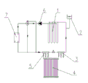
Fig. 1 is structural representation of the present utility model;
Reference numeral: 1, buried heat exchanger tube, 2, expansion water supply tank, 3, water collector, 4, capillary network heat exchanger, 5, water knockout drum, 6, water pump, 7, plate type heat exchanger.
The specific embodiment
As shown in the figure, a kind of indoor temperature regulating device, comprise the buried circulation line forming in underground buried heat exchanger tube 1 and the capillary network heat exchanger 4 being distributed on indoor canopy, the Inlet and outlet water two ends of described capillary network heat exchanger 4 are connected into circulation line by water knockout drum 5 and water collector 3 respectively, recirculated water in circulation line is driven by water pump 6, and in buried heat exchanger tube 1, emit heat to underground, the heat in capillary network heat exchanger 4 in absorption chamber.
Be more than basic embodiment of the present utility model, can on above basis, do further restriction or improvement:
As, described circulation line is also connected with plate type heat exchanger 7 by valve, and plate type heat exchanger 7 can be in parallel with capillary network heat exchanger 4 or be connected in series in circulation line, so that extra radiation low-temperature receiver to be provided;
As, described circulation line is also connected with expansion water supply tank 2, for replenishment cycles water;
As, described buried heat exchanger tube 1 is buried in underground, and the water water temperature that participates in circulation in control device of take is 17 ℃ ~ 19 ℃, thereby improves refrigerating efficiency and indoor comfort level;
As, in the outside of described circulation line, be coated with heat-barrier material, to prevent that circulation line from absorbing heat and then passing to recirculated water, causes the reduction of cooling effectiveness.
Claims (5)
1. an indoor temperature regulating device, it is characterized in that: comprise buried in underground buried heat exchanger tube (1) be distributed in the circulation line that capillary network heat exchanger (4) on indoor canopy forms, the Inlet and outlet water two ends of described capillary network heat exchanger (4) are connected into circulation line by water knockout drum (5) and water collector (3) respectively, recirculated water in circulation line is driven by water pump (6), and in buried heat exchanger tube (1), emit heat to underground, the heat in capillary network heat exchanger (4) in absorption chamber.
2. a kind of indoor temperature regulating device according to claim 1, is characterized in that: described circulation line is also connected with plate type heat exchanger (7) by valve.
3. a kind of indoor temperature regulating device according to claim 1, is characterized in that: described circulation line is also connected with expansion water supply tank (2).
4. a kind of indoor temperature regulating device according to claim 3, is characterized in that: described buried heat exchanger tube (1) is buried in underground, and the water water temperature that participates in circulation in control device of take is 17 ℃ ~ 19 ℃.
5. according to a kind of indoor temperature regulating device described in any one claim in claim 1-3, it is characterized in that: the outside of described circulation line is coated with heat-barrier material.
Priority Applications (1)
| Application Number | Priority Date | Filing Date | Title |
|---|---|---|---|
| CN201320576490.0U CN203550084U (en) | 2013-09-18 | 2013-09-18 | Indoor temperature regulator |
Applications Claiming Priority (1)
| Application Number | Priority Date | Filing Date | Title |
|---|---|---|---|
| CN201320576490.0U CN203550084U (en) | 2013-09-18 | 2013-09-18 | Indoor temperature regulator |
Publications (1)
| Publication Number | Publication Date |
|---|---|
| CN203550084U true CN203550084U (en) | 2014-04-16 |
Family
ID=50468193
Family Applications (1)
| Application Number | Title | Priority Date | Filing Date |
|---|---|---|---|
| CN201320576490.0U Expired - Fee Related CN203550084U (en) | 2013-09-18 | 2013-09-18 | Indoor temperature regulator |
Country Status (1)
| Country | Link |
|---|---|
| CN (1) | CN203550084U (en) |
Cited By (1)
| Publication number | Priority date | Publication date | Assignee | Title |
|---|---|---|---|---|
| CN103438532A (en) * | 2013-09-18 | 2013-12-11 | 河南科技大学 | Indoor temperature regulator |
-
2013
- 2013-09-18 CN CN201320576490.0U patent/CN203550084U/en not_active Expired - Fee Related
Cited By (2)
| Publication number | Priority date | Publication date | Assignee | Title |
|---|---|---|---|---|
| CN103438532A (en) * | 2013-09-18 | 2013-12-11 | 河南科技大学 | Indoor temperature regulator |
| CN103438532B (en) * | 2013-09-18 | 2017-01-11 | 河南科技大学 | Indoor temperature regulator |
Similar Documents
| Publication | Publication Date | Title |
|---|---|---|
| CN202757347U (en) | Solar-assisted heat pump system | |
| CN103453604B (en) | A kind of solar air-conditioner system | |
| CN202041020U (en) | Household air-source heat pump-floor radiation multifunctional system | |
| CN103438530B (en) | A kind ofly cold with ice conserve cold combined refrigeration system | |
| CN109373481B (en) | Kang body ventilation air conditioner and heating system with human body preferentially used | |
| CN101893299A (en) | Solar adsorption type air-conditioning system based on phase change cold accumulation | |
| CN205351845U (en) | Multiplexing heat pump set of multisource | |
| CN106016825A (en) | Solar and air source heat pump dual heat source tri-generation system | |
| CN103388922B (en) | Dual-compressor multifunctional air source heat pump air conditioner system | |
| CN209893505U (en) | Electric heat accumulating type cold and hot combined supply system based on composite phase change heat accumulation material | |
| CN201513995U (en) | Refrigerating system capable of utilizing ground temperature to provide cooling for buildings through floor warming system | |
| CN202648015U (en) | Indirect solar energy assisted air source heat pump radiant heating system | |
| CN202613556U (en) | Ground source heat pump heating system utilizing heating terminals for free cooling | |
| CN203550084U (en) | Indoor temperature regulator | |
| CN202204090U (en) | Cooling tower free refrigeration energy-saving device | |
| CN204345836U (en) | The geothermal heat pump air-conditioning system of high temperature retaining independent temperature-humidity control | |
| CN205351607U (en) | Multisource energy acquires system | |
| CN103438533B (en) | Earth-cooled room temperature adjusting method | |
| CN203550085U (en) | Ground cold and ice storage combined refrigeration system | |
| CN204063424U (en) | Commercial Complex air conditioner energy source recovery system | |
| CN203671807U (en) | Energy-saving integrated air conditioner for communication machine room | |
| CN202731665U (en) | Heat supplying air energy energy-saving window | |
| CN203550277U (en) | Indirect evaporation coupling solar cold and hot combined supplying system for rural family | |
| CN103322655B (en) | New and effective energy ladder uses closed cycle central air conditioner system | |
| CN103438532B (en) | Indoor temperature regulator |
Legal Events
| Date | Code | Title | Description |
|---|---|---|---|
| C14 | Grant of patent or utility model | ||
| GR01 | Patent grant | ||
| CF01 | Termination of patent right due to non-payment of annual fee |
Granted publication date: 20140416 Termination date: 20140918 |
|
| EXPY | Termination of patent right or utility model |