CN203548300U - 风机入口防护网快速拆装装置 - Google Patents
风机入口防护网快速拆装装置 Download PDFInfo
- Publication number
- CN203548300U CN203548300U CN201320581846.XU CN201320581846U CN203548300U CN 203548300 U CN203548300 U CN 203548300U CN 201320581846 U CN201320581846 U CN 201320581846U CN 203548300 U CN203548300 U CN 203548300U
- Authority
- CN
- China
- Prior art keywords
- protective net
- protective screening
- supporting plates
- assembling device
- supporting plate
- Prior art date
- Legal status (The legal status is an assumption and is not a legal conclusion. Google has not performed a legal analysis and makes no representation as to the accuracy of the status listed.)
- Expired - Fee Related
Links
Images

Abstract
本实用新型公开了风机入口防护网快速拆装装置,属于一种连接装置。本实用新型要解决的技术问题是:现有的风机入口防护网存在着拆装不方便、工人劳动强度大等缺陷。本实用新型为解决上述技术问题,所采用的技术方案是:包括多个防护网托板、蝶形螺栓以及活节螺栓,所述防护网托板的上部固定安装于风机入口法兰上,所述防护网托板上设有供防护网上部嵌入其中的凹槽,所述防护网的下部由蝶形螺栓固定于防护网托板的下部。本实用新型的优点是:结构简单,拆装方便,节约时间,降低工作强度。
Description
技术领域
本实用新型涉及一种风机入口防护网快速拆装装置,属于一种连接装置。
背景技术
风机入口防护网是一种对风机起保护作用的一种装置。目前,风机入口防护网大多是通过螺栓与风机入口进行连接的,也有少数是采用直接焊接的方式,对于防护网需要经常拆卸清洗的场合而言,以上的连接方式拆装很不方便,浪费大量的人工,不能满足广大使用者的使用需求。因此,应该提供一种新的技术方案来解决上述问题。
发明内容
本实用新型的目的是:针对上述不足,提供一种结构简单、拆装方便的风机入口防护网快速拆装装置。
为达到上述目的,本实用新型采用的技术方案是:
风机入口防护网快速拆装装置,包括防护网托板、蝶形螺栓以及活节螺栓,所述防护网托板的上部固定安装于风机入口法兰上,所述防护网托板上设有供防护网上部嵌入其中的凹槽,所述防护网的下部由蝶形螺栓固定于防护网托板的下部。
上述技术方案的有关内容作如下解释:
所述防护网上部通过活节螺栓固定。
所述活节螺栓上设有固定其位置的蝶形螺母。
由于上述技术方案运用,本实用新型与现有技术相比具有下列优点:
在防护网的安装和拆卸过程中,无需使用钣手等工具,只要用手拧动蝶形螺母即可,对于经常需要拆装防护网的场合或批量拆装防护网的场合十分方便,能有效节省时间和劳动强度。
附图说明
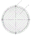
附图1为本实用新型实施例一结构示意图;
附图2为附图1侧视图;
附图3为附图2Ⅰ处结构放大图;
附图4为附图3Ⅱ处结构放大图。
以上附图中:1、风机入口法兰;2、蝶形螺母;3、活节螺栓;4、防护网;5、蝶形螺栓;6、防护网托板,7、凹槽。
具体实施方式
下面结合附图及实施例对本实用新型作进一步描述:
实施例一:
参见附图1至4所示,本实用新型风机入口防护网快速拆装装置,包括防护网托板6、蝶形螺栓5以及活节螺栓3,防护网托板6的上部固定安装于风机入口法兰1上,防护网托板6上设有供防护网4上部嵌入其中的凹槽7,防护网4上部通过活节螺栓3固定,活节螺栓3上设有固定其位置的蝶形螺母2,防护网的下部由蝶形螺栓5固定于防护网托板6的下部。在本实施例中,采用3只防护网托板6,每只防护网托板6分别固定于风机入口法兰1的上、下不同的位置上,安装防护网时,防护网4由防护网托板6的上部嵌入,其下部再由蝶型螺栓5固定住,扳动上部活节螺栓3,卡在上部凹槽7处,最后用蝶形螺母2固定好活节螺栓3,拆卸防护网时与上述过程相反。
上述实施例只为说明本实用新型的技术构思及特点,其目的在于让熟悉此项技术的人士能够了解本实用新型的内容并据以实施,并不能以此限制本实用新型的保护范围。凡根据本实用新型精神实质所作的等效变化或修饰,都应涵盖在本实用新型的保护范围之内。
Claims (3)
1.风机入口防护网快速拆装装置,其特征在于:包括多个防护网托板、蝶形螺栓以及活节螺栓,所述防护网托板的上部固定安装于风机入口法兰上,所述防护网托板上设有供防护网上部嵌入其中的凹槽,所述防护网的下部由蝶形螺栓固定于防护网托板的下部。
2.根据权利要求1所述的风机入口防护网快速拆装装置,其特征在于:所述防护网上部通过活节螺栓固定。
3.根据权利要求1或2所述的风机入口防护网快速拆装装置,其特征在于:所述活节螺栓上设有固定其位置的蝶形螺母。
Priority Applications (1)
| Application Number | Priority Date | Filing Date | Title |
|---|---|---|---|
| CN201320581846.XU CN203548300U (zh) | 2013-09-22 | 2013-09-22 | 风机入口防护网快速拆装装置 |
Applications Claiming Priority (1)
| Application Number | Priority Date | Filing Date | Title |
|---|---|---|---|
| CN201320581846.XU CN203548300U (zh) | 2013-09-22 | 2013-09-22 | 风机入口防护网快速拆装装置 |
Publications (1)
| Publication Number | Publication Date |
|---|---|
| CN203548300U true CN203548300U (zh) | 2014-04-16 |
Family
ID=50466424
Family Applications (1)
| Application Number | Title | Priority Date | Filing Date |
|---|---|---|---|
| CN201320581846.XU Expired - Fee Related CN203548300U (zh) | 2013-09-22 | 2013-09-22 | 风机入口防护网快速拆装装置 |
Country Status (1)
| Country | Link |
|---|---|
| CN (1) | CN203548300U (zh) |
Cited By (2)
| Publication number | Priority date | Publication date | Assignee | Title |
|---|---|---|---|---|
| CN108077729A (zh) * | 2017-12-23 | 2018-05-29 | 安徽王仁和米线食品有限公司 | 一种清洁型米线生产用米线机 |
| CN111911427A (zh) * | 2020-09-23 | 2020-11-10 | 江西艾斯欧匹精密智造科技有限公司 | 一种防堵的风机 |
-
2013
- 2013-09-22 CN CN201320581846.XU patent/CN203548300U/zh not_active Expired - Fee Related
Cited By (2)
| Publication number | Priority date | Publication date | Assignee | Title |
|---|---|---|---|---|
| CN108077729A (zh) * | 2017-12-23 | 2018-05-29 | 安徽王仁和米线食品有限公司 | 一种清洁型米线生产用米线机 |
| CN111911427A (zh) * | 2020-09-23 | 2020-11-10 | 江西艾斯欧匹精密智造科技有限公司 | 一种防堵的风机 |
Similar Documents
| Publication | Publication Date | Title |
|---|---|---|
| CN204138210U (zh) | 一种定型化塔吊操作平台及安全通道 | |
| CN203548300U (zh) | 风机入口防护网快速拆装装置 | |
| CN204679925U (zh) | 一种新型基于快拆结构的计算机防尘机箱 | |
| CN203334720U (zh) | 一种新型一体化洁净手术室 | |
| CN206066280U (zh) | 一种深井泵拆装卡具 | |
| CN204421220U (zh) | 空调外机防护装置 | |
| CN205104874U (zh) | 新型u型走线架 | |
| CN202900985U (zh) | 一种可拆卸式工字轮 | |
| CN202194847U (zh) | 一种风机底座 | |
| CN204645238U (zh) | 污水密闭收集提升装置 | |
| CN208687343U (zh) | 一种一体式侧板 | |
| CN205818388U (zh) | 可在线快速拆卸更换加热棒的模头接线盒结构 | |
| CN202836010U (zh) | 具有可拆卸底座的冷藏柜 | |
| CN209013242U (zh) | 一种平头炉 | |
| CN203992704U (zh) | 一种回流焊机 | |
| CN204079287U (zh) | 一种起重机辅助支架 | |
| CN203548281U (zh) | 可拆卸风机 | |
| CN202102646U (zh) | 一种立体字安装构件 | |
| CN202320160U (zh) | 可翻转三段式金属保险杠 | |
| CN205028742U (zh) | 可拆卸式双面通风箱体横撑 | |
| CN201474878U (zh) | 一种风机变频器冷却装置的安装支撑框架 | |
| CN203129384U (zh) | 一种幕墙保温板的安装支架 | |
| CN207526667U (zh) | 一种基于压缩机气缸工艺孔的电磁阀安装支撑 | |
| CN204089563U (zh) | 一种风扇易维护的变频器 | |
| CN202516611U (zh) | 一种粮食研磨机的可拆卸的活动式钢连接构件 |
Legal Events
| Date | Code | Title | Description |
|---|---|---|---|
| C14 | Grant of patent or utility model | ||
| GR01 | Patent grant | ||
| CF01 | Termination of patent right due to non-payment of annual fee |
Granted publication date: 20140416 Termination date: 20190922 |
|
| CF01 | Termination of patent right due to non-payment of annual fee |