CN203521040U - Communication cable - Google Patents
Communication cable Download PDFInfo
- Publication number
- CN203521040U CN203521040U CN201320577875.9U CN201320577875U CN203521040U CN 203521040 U CN203521040 U CN 203521040U CN 201320577875 U CN201320577875 U CN 201320577875U CN 203521040 U CN203521040 U CN 203521040U
- Authority
- CN
- China
- Prior art keywords
- layer
- reinforced layer
- interior reinforced
- communication cable
- cable
- Prior art date
- Legal status (The legal status is an assumption and is not a legal conclusion. Google has not performed a legal analysis and makes no representation as to the accuracy of the status listed.)
- Expired - Fee Related
Links
Images
Abstract
The utility model relates to a communication cable which comprises, sequentially from the external to the internal, an oversheath layer and an inner reinforcing layer, wherein the inner reinforcing layer comprises a plurality of wrapping core wires, two metallic detection wires which are parallel with the core wires are arranged between the oversheath layer and the inner reinforcing layer and the two metallic detection wires are symmetrically arranged. When the communication cable employs such a structure, two metallic detection wires form a loop. One metallic detection wire sends signals, and the other receives signals. The communication cable actively obtains cable information, and detected wire fault information is high in reliability.
Description
Technical field
The utility model relates to a kind of communications cable, is specifically a kind of communications cable that contains detection line.
Background technology
The existing communications cable with detection line, generally comprise successively from outside to inside external sheath layer and interior reinforced layer, in interior reinforced layer, be wrapped in heart yearn, heart yearn has cable line, cable etc., parallelly with heart yearn between external sheath layer and interior reinforced layer is provided with a metal detection line.By checkout gear connection metal detection line, can judge fast whether fault of cable, thereby facilitate scheduling and the management of whole distributing system.But only have a detection line, checkout gear can only be passive obtain the information of cable break-make, cannot adopt and send signal, then receive this mode active obtaining of signal cable information, reliability is not enough.
Utility model content
Technical problem to be solved in the utility model has been to provide and has detected the higher communications cable of cable fault message reliability.
For solving the problems of the technologies described above, the utility model discloses a kind of communications cable, it comprises external sheath layer and interior reinforced layer from outside to inside successively, in interior reinforced layer, be enclosed with many heart yearns, between external sheath layer and interior reinforced layer, be arranged with two metal detection lines in parallel with heart yearn, described two metal detection lines are symmetrical arranged.
Adopt after said structure, can form loops by two metal detection lines, one is used for transmitted signal, and one is used for receiving signal, like this can active obtaining cable information, and the reliability that detects cable fault message is higher.
In described interior reinforced layer, being also provided with cross section is criss-cross dividing plate, and described heart yearn is located at respectively in the space between dividing plate and interior reinforced layer.Adopt this structure, dividing plate plays a supportive role, and prevents from can damaging heart yearn after the communications cable from flattening.Make the reliability of the communications cable higher.
Accompanying drawing explanation
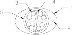
Fig. 1 is the structural representation of the utility model communications cable.
As shown in the figure: 1, external sheath layer, 2, metal detection line, 3, heart yearn, 4, dividing plate, 5, interior reinforced layer.
Embodiment
Below in conjunction with the drawings and specific embodiments, the utility model is described in further detail:
As shown in Figure 1, the utility model discloses a kind of communications cable, it comprises external sheath layer 1 and interior reinforced layer 5 from outside to inside successively, in interior reinforced layer 5, be enclosed with many heart yearns 3, between external sheath layer 1 and interior reinforced layer 5, be arranged with two metal detection lines 2 in parallel with heart yearn 3, described two metal detection lines 2 are symmetrical arranged.Described external sheath layer 1 is generally PVC material and makes, and interior reinforced layer 5 is made for aramid fiber, and described heart yearn 3 has the structures such as optical fiber and electric wire.
In described interior reinforced layer 5, being also provided with cross section is criss-cross dividing plate 4, and described heart yearn 3 is located at respectively in the space between dividing plate 4 and interior reinforced layer 5.In the present embodiment, heart yearn 3 has 8, establishes two heart yearns in each space between dividing plate 4 and interior reinforced layer 5.Adopt this structure, dividing plate plays a supportive role, and prevents from can damaging heart yearn after the communications cable from flattening.Make the reliability of the communications cable higher.
Claims (2)
1. the communications cable, it comprises external sheath layer (1) and interior reinforced layer (5) from outside to inside successively, in interior reinforced layer (5), be enclosed with many heart yearns (3), it is characterized in that: between external sheath layer (1) and interior reinforced layer (5), be arranged with two metal detection lines (2) in parallel with heart yearn (3), described two metal detection lines (2) are symmetrical arranged.
2. the communications cable according to claim 1, is characterized in that: in described interior reinforced layer (5), being also provided with cross section is criss-cross dividing plate (4), and described heart yearn (3) is located at respectively in the space between dividing plate (4) and interior reinforced layer (5).
Priority Applications (1)
| Application Number | Priority Date | Filing Date | Title |
|---|---|---|---|
| CN201320577875.9U CN203521040U (en) | 2013-09-17 | 2013-09-17 | Communication cable |
Applications Claiming Priority (1)
| Application Number | Priority Date | Filing Date | Title |
|---|---|---|---|
| CN201320577875.9U CN203521040U (en) | 2013-09-17 | 2013-09-17 | Communication cable |
Publications (1)
| Publication Number | Publication Date |
|---|---|
| CN203521040U true CN203521040U (en) | 2014-04-02 |
Family
ID=50379932
Family Applications (1)
| Application Number | Title | Priority Date | Filing Date |
|---|---|---|---|
| CN201320577875.9U Expired - Fee Related CN203521040U (en) | 2013-09-17 | 2013-09-17 | Communication cable |
Country Status (1)
| Country | Link |
|---|---|
| CN (1) | CN203521040U (en) |
Cited By (3)
| Publication number | Priority date | Publication date | Assignee | Title |
|---|---|---|---|---|
| CN105575520A (en) * | 2016-03-05 | 2016-05-11 | 无锡南理工科技发展有限公司 | Reinforced communication cable |
| CN105575519A (en) * | 2016-03-05 | 2016-05-11 | 无锡南理工科技发展有限公司 | Communication cable for information transmission |
| CN105702376A (en) * | 2016-04-07 | 2016-06-22 | 无锡南理工科技发展有限公司 | Double-shielded insulated communication cable |
-
2013
- 2013-09-17 CN CN201320577875.9U patent/CN203521040U/en not_active Expired - Fee Related
Cited By (3)
| Publication number | Priority date | Publication date | Assignee | Title |
|---|---|---|---|---|
| CN105575520A (en) * | 2016-03-05 | 2016-05-11 | 无锡南理工科技发展有限公司 | Reinforced communication cable |
| CN105575519A (en) * | 2016-03-05 | 2016-05-11 | 无锡南理工科技发展有限公司 | Communication cable for information transmission |
| CN105702376A (en) * | 2016-04-07 | 2016-06-22 | 无锡南理工科技发展有限公司 | Double-shielded insulated communication cable |
Similar Documents
| Publication | Publication Date | Title |
|---|---|---|
| CN203521040U (en) | Communication cable | |
| CN203536090U (en) | Multi-core cable | |
| CN203465978U (en) | Photoelectric composite power cable for intelligent power grid | |
| CN204130223U (en) | A kind of buffering Anti-seismic communication system core level cable | |
| CN103824643A (en) | Triangle communication cable | |
| CN203366851U (en) | Photoelectric composite cable | |
| CN203366836U (en) | High-strength fiber composite low-voltage cable | |
| CN203300310U (en) | Optical-fiber composite low-voltage cable | |
| CN203217982U (en) | High-temperature resistant flat cable for overhead crane | |
| CN104254087A (en) | GPRS (general packet radio service)-based wireless network monitoring system | |
| CN203165526U (en) | Shielding type power line | |
| CN202748506U (en) | Flexible optical cable capable of being knotted | |
| CN202454322U (en) | Photoelectric composite cable | |
| CN203102915U (en) | Tensile low temperature-resistant control flexible cable | |
| CN203826100U (en) | Five-core optical-fiber composite low-voltage cable | |
| CN202816415U (en) | Cable | |
| CN202939333U (en) | Layer stranded remote optical cable | |
| CN203242376U (en) | Movable flexible cable for overhead travelling crane | |
| CN203150220U (en) | High-tensile special fire-resistant cable | |
| CN203085261U (en) | A scalloped multi-core power cable | |
| CN211208020U (en) | Watertight bearing comprehensive special-shaped flat cable | |
| CN202189598U (en) | Multicore composite cable with shielding function | |
| CN105336409A (en) | Four-core composite shock-insulation flat cable | |
| CN203433858U (en) | Local cable | |
| CN203311874U (en) | Data signal and radiofrequency signal integrated transmission electric cable |
Legal Events
| Date | Code | Title | Description |
|---|---|---|---|
| C14 | Grant of patent or utility model | ||
| GR01 | Patent grant | ||
| CF01 | Termination of patent right due to non-payment of annual fee |
Granted publication date: 20140402 Termination date: 20160917 |
|
| CF01 | Termination of patent right due to non-payment of annual fee |