CN203518612U - Smelter with heat-resisting smelter nozzle - Google Patents
Smelter with heat-resisting smelter nozzle Download PDFInfo
- Publication number
- CN203518612U CN203518612U CN201320569225.XU CN201320569225U CN203518612U CN 203518612 U CN203518612 U CN 203518612U CN 201320569225 U CN201320569225 U CN 201320569225U CN 203518612 U CN203518612 U CN 203518612U
- Authority
- CN
- China
- Prior art keywords
- smelter
- water inlet
- converter nose
- outlet pipe
- inlet pipe
- Prior art date
- Legal status (The legal status is an assumption and is not a legal conclusion. Google has not performed a legal analysis and makes no representation as to the accuracy of the status listed.)
- Expired - Fee Related
Links
Images

Abstract
The utility model discloses a smelter with a heat-resisting smelter nozzle. The smelter comprises a smelter body and the smelter nozzle arranged at a discharging opening of the smelter body. The smelter nozzle comprises a smelter nozzle body, and a groove channel with an opened top is arranged in the upper portion of the smelter body in the length direction. A cooling channel with a U-shaped cross section is arranged in the smelter nozzle body, and a water inlet pipe and a water outlet pipe are arranged on the two sides of the groove channel of the smelter nozzle body respectively. The water outlet end of the water inlet pipe and the water inlet end of the water outlet pipe are communicated with the cooling channel respectively. The water inlet pipe and/or the water outlet pipe are/is provided with manual adjusting valves/a manual adjusting valve. According to the technical scheme, high-temperature melting liquid in the smelter is poured out through the groove channel in the smelter body. Due to the fact that the cooling channel is arranged in the smelter nozzle body, namely cold water enters the cooling channel through the water inlet pipe and is discharged through the water outlet pipe, water in the cooling channel takes heat subjected by the smelter nozzle body away so that the temperature of the smelter nozzle body can be lowered to a certain degree, and therefore the service life of the smelter nozzle body is prolonged.
Description
Technical field
The utility model belongs to refractory material production technical field, relates in particular to a kind of smelting furnace with high temperature resistant converter nose.
Background technology
Smelting furnace is equipment conventional in refractory material production process, but because the high-temperature fusion liquid in smelting furnace need to be poured out by the smelting furnace with high temperature resistant converter nose, the high temperature resistant degree of smelting furnace with high temperature resistant converter nose is low, having used of a specified duration will be burned, just need to change converter nose, this has just increased cost virtually.
Utility model content
The utility model, in order to solve weak point of the prior art, provides the smelting furnace with high temperature resistant converter nose that a kind of heat-resisting quantity is strong.
For solving the problems of the technologies described above, the utility model adopts following technical scheme: the smelting furnace with high temperature resistant converter nose, comprise smelting furnace body and the converter nose that is located at smelting furnace body discharging opening, described converter nose comprises converter nose body, converter nose body top is provided with the recess channels of open top along its length, in converter nose body, be provided with cross section and be U-shaped cooling duct, converter nose body is respectively equipped with water inlet pipe and outlet pipe in recess channels both sides, the water side of water inlet pipe and the water inlet end of outlet pipe are communicated with cooling duct respectively, and water inlet pipe and/or outlet pipe are provided with manual modulation valve.
Described water inlet pipe and outlet pipe are all inverted U structure.
Adopt technique scheme, the intrinsic high-temperature fusion liquid of smelting furnace is poured out by the recess channels on converter nose body, owing in converter nose body, cooling duct being set, be that cold water is entered in cooling duct by water inlet pipe, then by outlet pipe, discharge, the heat that in cooling duct, water is subject to converter nose body is taken away, and makes converter nose body reduce certain temperature, thereby extends the service life of converter nose body.Manual modulation valve is for regulating cooling water by the flow velocity of cooling duct, the i.e. cooling effectiveness to converter nose body according to actual conditions adjustment, water inlet pipe and outlet pipe are all inverted U structure, be that the water inlet of water inlet pipe and the delivery port of outlet pipe all arrange down, so more save space and be difficult for the workman that damages.
Accompanying drawing explanation
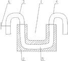
Fig. 1 is structural representation of the present utility model;
Fig. 2 is the schematic cross-sectional view of converter nose in the middle of Fig. 1.
The specific embodiment
As depicted in figs. 1 and 2, the smelting furnace with high temperature resistant converter nose of the present utility model, the converter nose 7 that comprises smelting furnace body 8 and be located at smelting furnace body 8 discharging openings, converter nose 7 comprises converter nose body 2, converter nose body 2 tops are provided with the recess channels 1 of open top along its length, in converter nose body 2, be provided with cross section and be U-shaped cooling duct 5, converter nose body 2 is respectively equipped with water inlet pipe 3 and outlet pipe 4 in recess channels 1 both sides, the water inlet end of the water side of water inlet pipe 3 and outlet pipe 4 is communicated with cooling duct 5 respectively, and water inlet pipe 3 is provided with manual modulation valve 6.Certainly, manual modulation valve 6 also can be located on outlet pipe 4, and manual modulation valve 6 can also be located at respectively on water inlet pipe 3 and outlet pipe 4.Water inlet pipe 3 and outlet pipe 4 are all inverted U structure.In addition, can on converter nose body 2, handle be set, be convenient to like this carrying and dismounting.
Smelting furnace body 8 in the middle of the utility model is existing mature technology, and concrete structure repeats no more.
When the utility model is used in work, high-temperature fusion liquid in smelting furnace body 8 is poured out by the recess channels 1 on converter nose body 2, due in the interior cooling duct 5 that arranges of converter nose body 2, be that cold water is entered in cooling duct 5 by water inlet pipe 3, then by outlet pipe 4, discharge, the heat that in cooling duct 5, water is subject to converter nose body 2 is taken away, and makes converter nose body 2 reduce certain temperature, thereby extends the service life of converter nose body 2.Water inlet pipe 3 and outlet pipe 4 are all inverted U structure, and the delivery port of the water inlet of water inlet pipe 3 and outlet pipe 4 all arranges down, so more saves space.
Claims (2)
1. the smelting furnace with high temperature resistant converter nose, comprise smelting furnace body and the converter nose that is located at smelting furnace body discharging opening, it is characterized in that: described converter nose comprises converter nose body, converter nose body top is provided with the recess channels of open top along its length, in converter nose body, be provided with cross section and be U-shaped cooling duct, converter nose body is respectively equipped with water inlet pipe and outlet pipe in recess channels both sides, the water side of water inlet pipe and the water inlet end of outlet pipe are communicated with cooling duct respectively, and water inlet pipe and/or outlet pipe are provided with manual modulation valve.
2. the smelting furnace with high temperature resistant converter nose according to claim 1, is characterized in that: described water inlet pipe and outlet pipe are all inverted U structure.
Priority Applications (1)
| Application Number | Priority Date | Filing Date | Title |
|---|---|---|---|
| CN201320569225.XU CN203518612U (en) | 2013-09-14 | 2013-09-14 | Smelter with heat-resisting smelter nozzle |
Applications Claiming Priority (1)
| Application Number | Priority Date | Filing Date | Title |
|---|---|---|---|
| CN201320569225.XU CN203518612U (en) | 2013-09-14 | 2013-09-14 | Smelter with heat-resisting smelter nozzle |
Publications (1)
| Publication Number | Publication Date |
|---|---|
| CN203518612U true CN203518612U (en) | 2014-04-02 |
Family
ID=50377535
Family Applications (1)
| Application Number | Title | Priority Date | Filing Date |
|---|---|---|---|
| CN201320569225.XU Expired - Fee Related CN203518612U (en) | 2013-09-14 | 2013-09-14 | Smelter with heat-resisting smelter nozzle |
Country Status (1)
| Country | Link |
|---|---|
| CN (1) | CN203518612U (en) |
Cited By (1)
| Publication number | Priority date | Publication date | Assignee | Title |
|---|---|---|---|---|
| CN108204744A (en) * | 2017-12-05 | 2018-06-26 | 鄂尔多斯市君正能源化工有限公司 | A kind of furnace of calcium carbide converter nose and furnace of calcium carbide |
-
2013
- 2013-09-14 CN CN201320569225.XU patent/CN203518612U/en not_active Expired - Fee Related
Cited By (2)
| Publication number | Priority date | Publication date | Assignee | Title |
|---|---|---|---|---|
| CN108204744A (en) * | 2017-12-05 | 2018-06-26 | 鄂尔多斯市君正能源化工有限公司 | A kind of furnace of calcium carbide converter nose and furnace of calcium carbide |
| CN108204744B (en) * | 2017-12-05 | 2019-06-21 | 鄂尔多斯市君正能源化工有限公司 | A kind of furnace of calcium carbide converter nose and furnace of calcium carbide |
Similar Documents
| Publication | Publication Date | Title |
|---|---|---|
| CN202377525U (en) | Device for cooling stopper of continuous casting machine | |
| CN203518612U (en) | Smelter with heat-resisting smelter nozzle | |
| CN204125474U (en) | A kind of hot molten slag gets slag device online | |
| CN205275649U (en) | Novel water -cooling stove roller | |
| CN216223732U (en) | Flue gas denitration facility of melamine molten salt furnace | |
| CN201974060U (en) | Water jacket type chute | |
| CN203421973U (en) | Furnace nozzle of electric melting furnace | |
| CN205376257U (en) | Hot stove transformer cooling device in ore deposit | |
| CN202254860U (en) | High efficiency heat exchange casting copper water jacket | |
| CN211012424U (en) | Smelting and standing integrated aluminum melting furnace | |
| CN104152697B (en) | A kind of waste aluminum retrieving arrangement | |
| CN204665906U (en) | The lower water jacket of modified air blast smelting furnace | |
| CN201825863U (en) | Glass fiber bushing cooler | |
| CN208012353U (en) | A kind of shaft furnace with shaft furnace anticollision furnace wall | |
| CN204359135U (en) | With the electric furnace converter nose of cooling device | |
| CN205332788U (en) | Lithium electricity material kiln with novel heat sink | |
| CN201530834U (en) | Porous channel cooling device on blast-furnace damaged cooling stave | |
| CN204718422U (en) | A kind of furnace cupola of waste heat recovery | |
| CN201092582Y (en) | Slag discharging device for metal vacuum smelting reduction still | |
| CN204080052U (en) | A kind of waste aluminum retrieving arrangement | |
| CN203464741U (en) | High-efficiency saving type pipeline structure for steel refining furnace | |
| CN204455253U (en) | A kind of device improving top blow smelting stove furnace roof cold-zone temperature | |
| CN203065506U (en) | Temperature control and cooling control device for feeding system of continuous steelmaking electric furnace | |
| CN209568125U (en) | A kind of outer nozzle brick and the converter slag-resisting device with the outer nozzle brick | |
| CN204125472U (en) | A kind of hot molten slag shunting flap arrangement |
Legal Events
| Date | Code | Title | Description |
|---|---|---|---|
| C14 | Grant of patent or utility model | ||
| GR01 | Patent grant | ||
| CF01 | Termination of patent right due to non-payment of annual fee |
Granted publication date: 20140402 Termination date: 20140914 |
|
| EXPY | Termination of patent right or utility model |