CN203515025U - Mechanical lock - Google Patents
Mechanical lock Download PDFInfo
- Publication number
- CN203515025U CN203515025U CN201320664207.XU CN201320664207U CN203515025U CN 203515025 U CN203515025 U CN 203515025U CN 201320664207 U CN201320664207 U CN 201320664207U CN 203515025 U CN203515025 U CN 203515025U
- Authority
- CN
- China
- Prior art keywords
- housing
- handle mounting
- mounting blocks
- catch
- casing
- Prior art date
- Legal status (The legal status is an assumption and is not a legal conclusion. Google has not performed a legal analysis and makes no representation as to the accuracy of the status listed.)
- Expired - Lifetime
Links
Images


Abstract
The utility model discloses a mechanical lock which comprises a casing. a main spring bolt and a latch bolt are mounted in the casing, the inner end of the main spring bolt is connected on a sliding plate, the sliding plate is transversely and slidingly mounted in the casing, the inner end of the latch bolt is connected with a sliding rod, a reset spring is sleeved on the sliding rod, the outer end of the reset spring is abutted on the inner end face of the spring bolt, and the inner end of the reset spring is fixed on a baffle plate of the casing. a lock cylinder mounting groove and a handle mounting block are arranged in the casing, the handle mounting block is rotatably mounted in the casing, a mounting hole used for mounting a handle is formed in the middle of the handle mounting block, an upper shifting fork is mounted outside the handle mounting block and is rotatably matched outside the handle mounting block, an arc groove is arranged on the inner side face of the upper shifting fork, a clamp arranged in the arc groove in a matched manner is disposed on the handle mounting block, an extension portion is arranged on an external side of the upper shifting fork and is clamped on a catch of the outer end of the sliding rod, a sliding groove is arranged on the casing, and the catch is slidingly mounted in the sliding groove. A limit plate fixed in the casing is arranged behind the sliding rod. A connecting rod is movably connected with the upper shifting fork, and the other end of the connecting rod is connected on the sliding plate.
Description
Technical field
The utility model relates to lockset, especially a kind of mechanical lock for mechanical lock or smart lock.
Background technology
At present, do on the market the producer of locking a lot, a part is engaged in mechanical lock, the smart lock that a part grows up on the basis of mechanical lock.Because smart lock relates to mechanical control section, just there are a lot of drivers and control panel to be placed on lock body the inside, cause lock body integral body partially thick.But some thickness gates very thin (particularly timber), so for being installed, lock body need on door leaf, draw very large hole when mounted.So likely make door leaf lose enough intensity, particularly veneer door, brings certain potential safety hazard to user's use.
And mechanical lock structure is comparatively simple, but the lock body of mechanical lock is difficult to smart lock lock body, is difficult to mechanical lock, because the structure of mechanical lock and smart lock is different for the lock body of smart lock.Master lock tongue and latch bolt are installed on lock body, and the master lock tongue on mechanical lock is to control by lock core, is to open or closed master lock tongue with key, latch bolt is to control by handle, the effect of latch bolt is to allow door-plate fix on doorframe, does not play locked effect, and the control of general master lock tongue and latch bolt separates.And smart lock is different, if at present conventional Fingerprint Lock, kayser, coded lock etc., most smart lock is there is no handle, directly controls the keying of master lock tongue and latch bolt by driver and control panel, therefore mechanical lock and smart lock difference structurally, make it cannot be general.
Utility model content
The utility model will solve the shortcoming of above-mentioned prior art, and a kind of mechanical lock is provided, and it is simple in structure, thin thickness, and be applicable to being respectively used to mechanical lock and smart lock.
The utility model solves the technical scheme that its technical problem adopts: this mechanical lock, comprise housing, master lock tongue and latch bolt are installed in housing, the inner of master lock tongue is connected on slide plate, slide plate is laterally slidably mounted in housing, and the inner of latch bolt connects slide bar, and on slide bar, cover has back-moving spring, back-moving spring outer end withstands on latch bolt inner face, and back-moving spring the inner withstands on the baffle plate that is fixed on housing; In housing, be provided with lock core mounting groove and handle mounting blocks, handle mounting blocks rotates in holder housing, the centre of handle mounting blocks has for the installing hole of handle is installed, handle mounting blocks is provided with fork outward, upper fork is rotatably assorted outside handle mounting blocks, the medial surface of upper fork is provided with deep-slotted chip breaker, handle mounting blocks is provided with the fastener being equipped with in deep-slotted chip breaker, upper fork outside is provided with extension, extension is stuck on the catch of slide bar outer end, on housing, have chute, catch is slidably mounted in chute; At the rear of slide bar, be provided with the limiting plate being fixed in housing; Upper fork is also connected with a connecting rod, and the other end of this connecting rod is connected to slide plate.This structure design is ingenious, and the upper fork on handle mounting blocks and the effect of lower fork realize the positive and negative rotation of handle all can drive the unlatching of latch bolt, during like this as mechanical lock, is convenient to open the door; And by connecting rod, connect on slide plate on upper fork, make like this master lock tongue link together with latch bolt, while moving in master lock tongue, drive in latch bolt and move, reach the effect of opening the door fast.
For further perfect, on connecting rod, have regulating tank, in regulating tank, be provided with the fixture that is fixed on slide plate.Connecting rod is to be fixedly mounted on slide plate by fixture, and the regulating tank on connecting rod plays the length that regulates shrinking connecting-rod to connect.While shortening the length that connecting rod connects, make master lock tongue and latch bolt interlock, and the length that prolongation connecting rod connects or while unclamping fixture makes master lock tongue and latch bolt that interaction relation not occur.
Handle mounting blocks is provided with torsion spring and lower fork outward, and torsion spring set is outside handle mounting blocks, and the straight section portion at its two ends is stuck on the keeper of housing internal projection, and lower fork is fixed on outside handle mounting blocks and is provided with the projection between the two straight section portions of insertion; Housing is provided with the activity template being rotatably connected in housing, and one end of activity template stretches out and is stuck on lower fork, and the other end stretches out and is stuck on slide bar;
In housing, be also provided with and dial catch, dial catch longitudinal sliding motion and be arranged in housing, the side of slide plate is provided with row's projection, dials catch and is provided with the draw-in groove coordinating with projection, and in housing, be provided with the stage clip that the draw-in groove on group catch is pressed together on to projection.Like this when dialling projection on slide plate of draw-in groove on catch, locked master lock tongue, this structural strengthening master lock tongue locking resistance of failure, improve user's use safety.
The effect that the utility model is useful is: lock body of the present utility model, by the change of simple and mechanical structure, can be applicable to standard machinery lock, also can be applicable to smart lock (Fingerprint Lock, coded lock, kayser etc.).Handle mounting blocks in lock body rotates and all can drive in latch bolt and move at different directions, and master lock tongue in move and can drive latch bolt to move in together, reach the requirement of smart lock intelligent drives.This lock thickness is very thin, and lock body door leaf need not be drawn very large hole for lock body is installed, and guarantees door leaf intensity, for user security is used, provides safeguard, and has strengthened master lock tongue locking resistance of failure simultaneously, improves user's use safety.
Accompanying drawing explanation
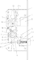
Fig. 1 is the front schematic view of the utility model internal construction;
Fig. 2 is internal construction schematic diagram of the present utility model;
Fig. 3 is internal construction schematic diagram of the present utility model;
Fig. 4 is the scheme of installation of handle mounting blocks in the utility model.
Description of reference numerals: housing 1, baffle plate 1-1, lock core mounting groove 1-2, keeper 1-3, master lock tongue 2, latch bolt 3, slide plate 4, projection 4-1, slide bar 5, catch 5-1, back-moving spring 6, handle mounting blocks 7, installing hole 7-1, fastener 7-2, upper fork 8, deep-slotted chip breaker 8-1, extension 8-2, lower fork 9, torsion spring 10, the 10-1 of straight section portion, activity template 11, limiting plate 12, connecting rod 13, regulating tank 13-1, fixture 14, dials catch 15, draw-in groove 15-1, stage clip 16.
The specific embodiment
Below in conjunction with accompanying drawing, the utility model is described in further detail:
With reference to accompanying drawing: this mechanical lock, comprise housing 1, the interior installation master lock of housing 1 tongue 2 and latch bolt 3, the inner of master lock tongue 2 is connected on slide plate 4, slide plate 4 is laterally slidably mounted in housing 1, and the inner of latch bolt 3 connects slide bar 5, and on slide bar 5, cover has back-moving spring 6, back-moving spring 6 outer ends withstand on latch bolt 3 inner faces, and back-moving spring 6 the inners withstand on the baffle plate 1-1 that is fixed on housing 1; In housing 1, be provided with lock core mounting groove 1-2 and handle mounting blocks 7, handle mounting blocks 7 rotates in holder housing 1, the centre of handle mounting blocks 7 has for the installing hole 7-1 of handle is installed, outer fork 8, torsion spring 10 and the lower fork 9 of being provided with of handle mounting blocks 7, torsion spring 10 is enclosed within outside handle mounting blocks 7, the 10-1 of straight section portion at its two ends is stuck on the keeper 1-3 of housing 1 internal projection, and lower fork 9 is fixed on outside handle mounting blocks 7 and is provided with the protruding 9-1 inserting between two 10-1 of straight section portion; Housing 1 is provided with the activity template 11 being rotatably connected in housing 1, and one end of activity template 11 stretches out and is stuck on lower fork 9, and the other end stretches out and is stuck on slide bar 5; Upper fork 8 is rotatably assorted at handle mounting blocks 7, the medial surface of upper fork 8 is provided with deep-slotted chip breaker 8-1, handle mounting blocks 7 is provided with the fastener 7-2 being equipped with in deep-slotted chip breaker 8-1, upper fork 8 outsides are provided with extension 8-2, extension 8-2 is stuck on the catch 5-1 of slide bar 5 outer ends, on housing 1, have chute 1-3, catch 5-1 is slidably mounted in chute 1-3; At the rear of slide bar 5, be provided with the limiting plate 12 being fixed in housing 1; Upper fork 8 is also connected with a connecting rod 13, and the other end of this connecting rod 13 is connected to slide plate 4.On connecting rod 13, have regulating tank 13-1, in regulating tank 13-1, be provided with the fixture 14 that is fixed on slide plate.
In housing 1, be also provided with and dial catch 15, dialling catch 15 longitudinal sliding motions is arranged in housing 1, the side of slide plate 4 is provided with row's projection 4-1, dials catch 15 and is provided with the draw-in groove 15-1 engaging with projection 4-1, and in housing 1, be provided with the stage clip 16 that the draw-in groove 15-1 on group catch 15 is pressed together on to projection 4-1.
This lock thickness is very thin, be convenient to be arranged in door, and this lock body can be according to required for mechanical lock or smart lock, if mechanical lock, only need are installed handle and lock core, and smart lock installation of driver and controller in lock core mounting groove.Wherein the positive and negative rotation of handle mounting blocks 7 all can drive and in latch bolt 3, moves and open the door, when handle mounting blocks 7 forward, fastener 7-1 on handle mounting blocks 7 is stuck in upper fork 8 forwards of drive in deep-slotted chip breaker 8-1, after extension 8-2 on upper fork 8 band moving slide-bar 5, move and pull latch bolt 3, and this at present fork 9 with activity template 11 in released state; When 7 reversion of handle mounting blocks, lower fork 9 hooks in one end of activity template 11 and drives its rotation, the other end of activity template 11 is stuck on slide bar 5 and drives to move thereafter and pulls latch bolt 3, and fastener 7-1 on handle mounting blocks 7 does not block deep-slotted chip breaker 8-1, and move in deep-slotted chip breaker 8-1, the rotating that therefore realizes handle mounting blocks 7 all can make to move in latch bolt 3.And between upper fork 8 and slide block 4, be connected with connecting rod 13, and in the process of moving, by connecting rod 13, promote fork 8 forwards in slide block 4, fork 8 is pulled in latch bolt 3 and move, and play the effect of interlock.Group catch 15 that strengthens its locking resistance of failure is installed on slide block 4, when opening master lock tongue, is needed first to dial catch 15 and move laterally.
Although the utility model illustrates and describes by reference to preferred embodiment,, those skilled in the art should understand, and in the scope of claims, can do the various variation in form and details.
Claims (4)
1. a mechanical lock, comprise housing (1), master lock tongue (2) and latch bolt (3) are installed in housing (1), the inner of master lock tongue (2) is connected on slide plate (4), slide plate (4) is laterally slidably mounted in housing (1), and the inner of described latch bolt (3) connects slide bar (5), and the upper cover of slide bar (5) has back-moving spring (6), back-moving spring (6) outer end withstands on latch bolt (3) inner face, and back-moving spring (6) the inner withstands on the baffle plate (1-1) that is fixed on housing (1), in housing (1), be provided with lock core mounting groove (1-2) and handle mounting blocks (7), handle mounting blocks (7) rotates in holder housing (1), the centre of handle mounting blocks (7) has the installing hole (7-1) for handle is installed, it is characterized in that: the outer fork (8) that is provided with of described handle mounting blocks (7), upper fork (8) is rotatably assorted in handle mounting blocks (7), the medial surface of upper fork (8) is provided with deep-slotted chip breaker (8-1), handle mounting blocks (7) is provided with the fastener (7-2) being equipped with in deep-slotted chip breaker (8-1), upper fork (8) outside is provided with extension (8-2), extension (8-2) is stuck on the catch (5-1) of slide bar (5) outer end, on housing (1), have chute (1-3), described catch (5-1) is slidably mounted in chute (1-3), at the rear of slide bar (5), be provided with the limiting plate (12) being fixed in housing (1), upper fork (8) is also connected with a connecting rod (13), and the other end of this connecting rod (13) is connected to slide plate (4).
2. mechanical lock according to claim 1, is characterized in that: on described connecting rod (13), have regulating tank (13-1), be provided with the fixture (14) that is fixed on slide plate in regulating tank (13-1).
3. mechanical lock according to claim 1, it is characterized in that: outer torsion spring (10) and the lower fork (9) of being provided with of described handle mounting blocks (7), torsion spring (10) is enclosed within outside handle mounting blocks (7), the straight section portion (10-1) at its two ends is stuck on the keeper (1-3) of housing (1) internal projection, and lower fork (9) is fixed on outside handle mounting blocks (7) and is provided with the projection (9-1) between the two straight section portions (10-1) of insertion; Housing (1) is provided with the activity template (11) being rotatably connected in housing (1), and one end of activity template (11) stretches out and is stuck in lower fork (9) above, and the other end stretches out and is stuck on slide bar (5).
4. mechanical lock according to claim 1, it is characterized in that: in described housing (1), be also provided with and dial catch (15), dialling catch (15) longitudinal sliding motion is arranged in housing (1), the side of described slide plate (4) is provided with row's projection (4-1), dial catch (15) and be provided with the draw-in groove (15-1) engaging with projection (4-1), and in housing (1), be provided with the stage clip (16) that the draw-in groove (15-1) on group catch (15) is pressed together on to projection (4-1).
Priority Applications (1)
| Application Number | Priority Date | Filing Date | Title |
|---|---|---|---|
| CN201320664207.XU CN203515025U (en) | 2013-10-28 | 2013-10-28 | Mechanical lock |
Applications Claiming Priority (1)
| Application Number | Priority Date | Filing Date | Title |
|---|---|---|---|
| CN201320664207.XU CN203515025U (en) | 2013-10-28 | 2013-10-28 | Mechanical lock |
Publications (1)
| Publication Number | Publication Date |
|---|---|
| CN203515025U true CN203515025U (en) | 2014-04-02 |
Family
ID=50373976
Family Applications (1)
| Application Number | Title | Priority Date | Filing Date |
|---|---|---|---|
| CN201320664207.XU Expired - Lifetime CN203515025U (en) | 2013-10-28 | 2013-10-28 | Mechanical lock |
Country Status (1)
| Country | Link |
|---|---|
| CN (1) | CN203515025U (en) |
Cited By (1)
| Publication number | Priority date | Publication date | Assignee | Title |
|---|---|---|---|---|
| CN104314383A (en) * | 2014-08-27 | 2015-01-28 | 温州华意利五金装饰有限公司 | Door lock |
-
2013
- 2013-10-28 CN CN201320664207.XU patent/CN203515025U/en not_active Expired - Lifetime
Cited By (2)
| Publication number | Priority date | Publication date | Assignee | Title |
|---|---|---|---|---|
| CN104314383A (en) * | 2014-08-27 | 2015-01-28 | 温州华意利五金装饰有限公司 | Door lock |
| CN104314383B (en) * | 2014-08-27 | 2017-07-21 | 温州华意利五金装饰有限公司 | A kind of door lock |
Similar Documents
| Publication | Publication Date | Title |
|---|---|---|
| CN204960528U (en) | Mortise lock's oblique tongue mechanism | |
| CN203515025U (en) | Mechanical lock | |
| CN202152569U (en) | Novel door lock | |
| CN201402434Y (en) | Computer case panel provided with sliding door | |
| CN206971974U (en) | A kind of intelligent anti-theft lock | |
| CN203978055U (en) | The concealed hasp of dynamoelectric dual-purpose | |
| CN201687279U (en) | Novel door lock | |
| CN203201300U (en) | Prying-resistant structure of mortise lock | |
| CN207700893U (en) | A kind of concealed door latch structure of automobile | |
| CN211173541U (en) | Rotary electronic cabinet lock | |
| CN208137669U (en) | A kind of Integral electric lock | |
| CN203769471U (en) | Cabinet door lock of equipment cabinet | |
| CN209538872U (en) | The push-and-pull unlocking mechanism of electronic lock | |
| CN207092742U (en) | A kind of computer box anti-theft locking component | |
| CN202380844U (en) | Secondary lock of automatic lock of roller shutter | |
| CN204804609U (en) | Safe type mechanism of locking a door | |
| CN208220441U (en) | World latch assembly | |
| CN207847310U (en) | A kind of novel distribution cabinet lockset | |
| CN202767694U (en) | Thin door-window screen leaf bolt lock with handle | |
| US20110138867A1 (en) | Fixed coded lock | |
| CN208618939U (en) | A kind of door lock front panel easy to assemble | |
| CN218668875U (en) | Intelligent lock with quick-unlocking structure | |
| CN202450872U (en) | Cabinet and door integrated locking mechanism plate | |
| CN209620815U (en) | Small push-and-pull transmission module | |
| CN2475785Y (en) | Structure-improved lock |
Legal Events
| Date | Code | Title | Description |
|---|---|---|---|
| C14 | Grant of patent or utility model | ||
| GR01 | Patent grant |