CN203471631U - Simple overturn-preventive adjusting device - Google Patents
Simple overturn-preventive adjusting device Download PDFInfo
- Publication number
- CN203471631U CN203471631U CN201320528631.1U CN201320528631U CN203471631U CN 203471631 U CN203471631 U CN 203471631U CN 201320528631 U CN201320528631 U CN 201320528631U CN 203471631 U CN203471631 U CN 203471631U
- Authority
- CN
- China
- Prior art keywords
- swing arm
- axle sleeve
- spring
- roller
- adjusting device
- Prior art date
- Legal status (The legal status is an assumption and is not a legal conclusion. Google has not performed a legal analysis and makes no representation as to the accuracy of the status listed.)
- Expired - Fee Related
Links
Images
Abstract
A simple overturn-preventive adjusting device relates to the metal processing field and is composed of a belt (1), a roller, an adjusting screw (4), a spring (9), a shaft sleeve, and a swing arm. By virtue of mounting the adjusting screw (4) and the spring (9) on the swing arm and rotating the adjusting screw (4) and the spring (9) on the swing arm, the problem that the swing arm of a mechanical type embracing device is easy to overturn excessively is solved. The simple overturn-preventive adjusting device is strong in practicality and relatively convenient to mount, maintain, and operate. Not only can the swing arm be prevented from excessive overturn when the embracing device is in the open state, but also the compaction degree of the roller (2) with respect to an embraced object (15) can be adjusted in the embracing state. Therefore, the production requirement is satisfied and the equipment security and production efficiency are improved.
Description
[technical field]
The utility model relates to metal manufacture field, especially relates to a kind of easy anti-canting adjusting device.
[background technology]
Known, in to the unit line of aluminium strip, foil production and processing, in hand type enclasp device swing arm to open and hold tightly be that the tension force, the size and Orientation that change belt by mechanical mechanism realized and opened and hold tightly, but existing machinery hand there will be the tight not or tension of embracing when holding tightly, when swing arm, open and there will be the swing arm excessive problem of overturning, just easy production development accident, thereby impact is produced, and bring impact can to the product of manufacturing out, affect direct economic benefit.
[summary of the invention]
In order to overcome the deficiency in background technology, the utility model discloses a kind of easy anti-canting adjusting device, the utility model is adjusted screw rod and spring by installing in swing arm, and by rotation, adjust the spring in screw rod and swing arm, the problem that the swing arm that solves mechanical type enclasp device with this is easily excessively turned up.
In order to realize described goal of the invention, the utility model adopts following technical scheme:
A kind of easy anti-canting adjusting device, comprise belt, roller, adjust screw rod, spring, axle sleeve and swing arm, mechanical type is held support body tightly and is provided with two fixedly swing arms, in office one by one fixedly one end of swing arm by bearing and manipulator, hold support body tightly and be flexibly connected, fixedly one end of swing arm is provided with the second swing arm and the 3rd swing arm, between the second swing arm and the 3rd swing arm, be provided with the second roller, the second roller is connected with the 3rd swing arm with the second swing arm by the key at its two ends, on the second swing arm and the 3rd swing arm homonymy one end, be respectively equipped with the first axle sleeve and the second axle sleeve, the first axle sleeve is connected with the 3rd swing arm with the second swing arm respectively with bolt by clamp with the second axle sleeve, on the first axle sleeve and the second axle sleeve, be respectively equipped with bearing pin, one end of the first swing arm is connected with the second axle sleeve with the first axle sleeve with the bearing pin on the second axle sleeve by the first axle sleeve, the other end of the first swing arm is provided with the first roller.
Described the first swing arm is provided with adjustment screw rod, adjusts screw rod and is connected with the first swing arm by nut.
Described the second swing arm and the 3rd swing arm are same structure, in the second swing arm or the 3rd swing arm, are provided with spring, and spring is connected with the first swing arm by the bumper post in the second swing arm or the 3rd swing arm.
Owing to having adopted technique scheme, the utlity model has following beneficial effect:
A kind of easy anti-canting adjusting device described in the utility model, comprise belt, roller, adjustment screw rod, spring, axle sleeve and swing arm, by installing, adjust screw rod and spring in swing arm, and by rotation, adjust the spring in screw rod and swing arm, the problem that the swing arm that solves mechanical type enclasp device with this is easily excessively turned up; The utility model is practical, installation and maintenance is all more convenient, operate more convenient, not only can prevent to enclasp device that swing arm from excessively overturning when the open mode, and can adjust while holding state tightly roller to holding the compression degree of thing tightly, thereby met need of production, improved security and the production efficiency of equipment.
[accompanying drawing explanation]
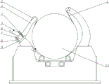
Fig. 1 is structural representation of the present utility model;
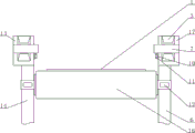
Fig. 2 is that the utility model A is to cutaway view;
In figure: 1, belt; 2, roller; 3, the first swing arm; 4, adjust screw rod; 5, nut; 6, the second swing arm; 7, bearing pin; 8, bumper post; 9, spring; 10, bolt; 11, clamp; 12, key; 13, axle sleeve; 14, the 3rd swing arm; 15, embraced thing; 16, the second roller; 17, the second axle sleeve.
[specific embodiment]
Explanation the utility model that can be detailed by the following examples, open the purpose of this utility model is intended to protect all technological improvements within the scope of the utility model.
A kind of easy anti-canting adjusting device described in 1 ~ 2 by reference to the accompanying drawings, comprise belt 1, roller, adjust screw rod 4, spring 9, axle sleeve and swing arm, manipulator is held support body tightly and is provided with two fixedly swing arms, in office one by one fixedly one end of swing arm by bearing and manipulator, hold support body tightly and be flexibly connected, fixedly one end of swing arm is provided with the second swing arm 6 and the 3rd swing arm 14, between the second swing arm 6 and the 3rd swing arm 14, be provided with the second roller 16, the second roller 16 is connected with the 3rd swing arm 14 with the second swing arm 6 by the key 12 at its two ends, on the second swing arm 6 and the 3rd swing arm 14 homonymy one end, be respectively equipped with the first axle sleeve 13 and the second axle sleeve 17, the first axle sleeve 13 is connected with the 3rd swing arm 14 with the second swing arm 6 respectively with bolt 10 by clamp 11 with the second axle sleeve 17, on the first axle sleeve 13 and the second axle sleeve 17, be respectively equipped with bearing pin 7, one end of the first swing arm 3 is connected with the second axle sleeve 17 with the first axle sleeve 13 with the bearing pin 7 on the second axle sleeve 17 by the first axle sleeve 13, the other end of the first swing arm 3 is provided with the first roller 2, described the first swing arm 3 is provided with adjusts screw rod 4, adjusts screw rod 4 and is connected with the first swing arm 3 by nut 5, described the second swing arm 6 and the 3rd swing arm 14 are same structure, in the second swing arm 6 or the 3rd swing arm 14, are provided with spring 9, and spring 9 is connected with the first swing arm 3 by the bumper post 8 in the second swing arm 6 or the 3rd swing arm 14.
Implement a kind of easy anti-canting adjusting device described in the utility model, at mechanical type enclasp device when holding state tightly, under the effect of belt 1, make roller be compressed embracing thing 15, the nut 5 of now adjusting on screw rod 4 by rotation outwards moves the first swing arm 3, so just can unclamp and be embraced thing 15; When roller compresses while being embraced thing 15 completely, by the nut 5 that rotation is adjusted on screw rod 4 round about, the first swing arm 3 is moved inward, thereby compress and embraced thing 15, while adjusting to correct position, fastening nut 5, at mechanical type enclasp device during in open mode, spring 9 between the first swing arm 3 and the second swing arm 6 or the 3rd swing arm 14 can be subject to the active force of the first swing arm 3 and the second swing arm 6 or the first swing arm 3 and the 3rd swing arm 14, guaranteed that the first swing arm 3 can excessively not overturn, thereby reduced the generation of contingency.
The utility model does not describe part in detail for prior art.
Claims (3)
1. an easy anti-canting adjusting device, comprise belt (1), roller, adjust screw rod (4), spring (9), axle sleeve and swing arm, manipulator is held support body tightly and is provided with two fixedly swing arms, in office one by one fixedly one end of swing arm by bearing and manipulator, hold support body tightly and be flexibly connected, fixedly one end of swing arm is provided with the second swing arm (6) and the 3rd swing arm (14), it is characterized in that: between the second swing arm (6) and the 3rd swing arm (14), be provided with the second roller (16), the second roller (16) is connected with the 3rd swing arm (14) with the second swing arm (6) by the key (12) at its two ends, on the second swing arm (6) and the 3rd swing arm (14) homonymy one end, be respectively equipped with the first axle sleeve (13) and the second axle sleeve (17), the first axle sleeve (13) is connected with the 3rd swing arm (14) with the second swing arm (6) respectively with bolt (10) by clamp (11) with the second axle sleeve (17), on the first axle sleeve (13) and the second axle sleeve (17), be respectively equipped with bearing pin (7), one end of the first swing arm (3) is connected with the second axle sleeve (17) with the first axle sleeve (13) with the bearing pin (7) on the second axle sleeve (17) by the first axle sleeve (13), the other end of the first swing arm (3) is provided with the first roller (2).
2. a kind of easy anti-canting adjusting device according to claim 1, is characterized in that: described the first swing arm (3) is provided with adjusts screw rod (4), adjusts screw rod (4) and is connected with the first swing arm (3) by nut (5).
3. a kind of easy anti-canting adjusting device according to claim 1, it is characterized in that: described the second swing arm (6) and the 3rd swing arm (14) are same structure, in the second swing arm (6) or the 3rd swing arm (14), be provided with spring (9), spring (9) is connected with the first swing arm (3) by the bumper post (8) in the second swing arm (6) or the 3rd swing arm (14).
Priority Applications (1)
| Application Number | Priority Date | Filing Date | Title |
|---|---|---|---|
| CN201320528631.1U CN203471631U (en) | 2013-08-28 | 2013-08-28 | Simple overturn-preventive adjusting device |
Applications Claiming Priority (1)
| Application Number | Priority Date | Filing Date | Title |
|---|---|---|---|
| CN201320528631.1U CN203471631U (en) | 2013-08-28 | 2013-08-28 | Simple overturn-preventive adjusting device |
Publications (1)
| Publication Number | Publication Date |
|---|---|
| CN203471631U true CN203471631U (en) | 2014-03-12 |
Family
ID=50220039
Family Applications (1)
| Application Number | Title | Priority Date | Filing Date |
|---|---|---|---|
| CN201320528631.1U Expired - Fee Related CN203471631U (en) | 2013-08-28 | 2013-08-28 | Simple overturn-preventive adjusting device |
Country Status (1)
| Country | Link |
|---|---|
| CN (1) | CN203471631U (en) |
Cited By (1)
| Publication number | Priority date | Publication date | Assignee | Title |
|---|---|---|---|---|
| CN113319761A (en) * | 2021-06-02 | 2021-08-31 | 安徽信息工程学院 | Pneumatic fixing device for vehicle assembly |
-
2013
- 2013-08-28 CN CN201320528631.1U patent/CN203471631U/en not_active Expired - Fee Related
Cited By (1)
| Publication number | Priority date | Publication date | Assignee | Title |
|---|---|---|---|---|
| CN113319761A (en) * | 2021-06-02 | 2021-08-31 | 安徽信息工程学院 | Pneumatic fixing device for vehicle assembly |
Similar Documents
| Publication | Publication Date | Title |
|---|---|---|
| CN203471631U (en) | Simple overturn-preventive adjusting device | |
| CN203614525U (en) | Communication device installing support | |
| CN209468034U (en) | A kind of roasting multifunctional crane gripping mechanism | |
| CN204750822U (en) | Correct support adjusting device that box warp | |
| CN203955762U (en) | Reel of uncoiler supports | |
| CN205310252U (en) | Robot gripping device | |
| CN203384594U (en) | Universal bracket | |
| CN203670419U (en) | Adjustable bolt locking mechanism | |
| CN202807956U (en) | Material pushing plate | |
| CN208342870U (en) | A kind of logistics box body crawl Industrial Robot Manipulator | |
| CN203272426U (en) | Connection structure and elastic clamp device connected through same | |
| CN203580998U (en) | Friction transferring assembly for point switch of tramcar and point switch therewith | |
| CN202301365U (en) | Mounting bolt specialized for vibration prevention of electric appliance box | |
| CN201590478U (en) | Microwave antenna hanger | |
| CN204851923U (en) | Disjunctor bolt | |
| CN204847302U (en) | Automatic upset material feeding unit | |
| CN204271994U (en) | A kind of frame with groove is fixing uses angle key | |
| CN204271991U (en) | A kind of frame of Novel belt groove is fixing uses angle key | |
| CN204966652U (en) | Large -scale whip antenna loading is rolled over flip -chip and is put | |
| CN203228163U (en) | Bolt and nut locking device | |
| CN204284095U (en) | A kind of frame with cascade function is fixed and is used angle key | |
| CN203651430U (en) | Storage battery bracket hook | |
| CN201820539U (en) | Novel L-shaped locking pin | |
| CN203438401U (en) | Discharging device of aggregate storage bin | |
| CN204271997U (en) | A kind of frame with groove is fixing uses Novel angle key |
Legal Events
| Date | Code | Title | Description |
|---|---|---|---|
| GR01 | Patent grant | ||
| GR01 | Patent grant | ||
| CF01 | Termination of patent right due to non-payment of annual fee | ||
| CF01 | Termination of patent right due to non-payment of annual fee |
Granted publication date: 20140312 Termination date: 20160828 |