CN203463847U - Double mechanically-sealed rotary joint - Google Patents

Double mechanically-sealed rotary joint Download PDF

Info

Publication number
CN203463847U
CN203463847U CN201320585594.8U CN201320585594U CN203463847U CN 203463847 U CN203463847 U CN 203463847U CN 201320585594 U CN201320585594 U CN 201320585594U CN 203463847 U CN203463847 U CN 203463847U
Authority
CN
China
Prior art keywords
seal ring
inlet end
end housing
hold
ring
Prior art date
Legal status (The legal status is an assumption and is not a legal conclusion. Google has not performed a legal analysis and makes no representation as to the accuracy of the status listed.)
Expired - Fee Related
Application number
CN201320585594.8U
Other languages
Chinese (zh)
Inventor
孙勇
Current Assignee (The listed assignees may be inaccurate. Google has not performed a legal analysis and makes no representation or warranty as to the accuracy of the list.)
YUHANG AEROSPACE EQUIPMENT CO., LTD.
Original Assignee
TENGZHOU YUHANG ROTARY JOINT MANUFACTURING Co Ltd
Priority date (The priority date is an assumption and is not a legal conclusion. Google has not performed a legal analysis and makes no representation as to the accuracy of the date listed.)
Filing date
Publication date
Application filed by TENGZHOU YUHANG ROTARY JOINT MANUFACTURING Co Ltd filed Critical TENGZHOU YUHANG ROTARY JOINT MANUFACTURING Co Ltd
Priority to CN201320585594.8U priority Critical patent/CN203463847U/en
Application granted granted Critical
Publication of CN203463847U publication Critical patent/CN203463847U/en
Anticipated expiration legal-status Critical
Expired - Fee Related legal-status Critical Current

Links

Images

Abstract

The utility model discloses a double mechanically-sealed rotary joint which comprises a plurality of seal rings, a shaft sleeve, an inlet end shell, an outlet end shell, an inlet end bearing cover, an outlet end bearing cover, an inlet end bearing gasket, an outlet end bearing gasket, an inlet end static ring base, an outlet end static ring base, an inlet end static seal ring, an outlet end static seal ring, an inlet end dynamic seal ring, an outlet end dynamic seal ring, a cylindrical helical compression spring, a deep groove ball bearing and an elastic cylindrical pin. The double mechanically-sealed rotary joint is characterized in that the inlet end shell is in bolted connection with the outlet end shell; the inlet end dynamic seal ring is arranged in the inlet end shell and sealed with the shaft sleeve; the inlet end bearing gasket is arranged at one end of the inlet end dynamic seal ring, and the inlet end static seal ring is arranged at the other end of the inlet end dynamic seal ring; the inlet end static seal ring is in sealed connection with the inlet end static ring base; the inlet end static seal ring is fixedly arranged in the inlet end shell and in sealed connection with the inlet end shell; the inlet end static seal ring and the inlet end dynamic seal ring are sealed in a dynamic and static manner and arranged in a rotation manner. The rotary joint has the advantages that the structural design is ingenious, the sealing performance is good, and the service life is long.

Description

A kind of double mechanical seal formula swivel joint
Technical field
The utility model belongs to swivel joint, particularly a kind of double mechanical seal formula swivel joint.
Background technique
In prior art, swivel joint is used when high speed, hot environment, by with relatively simple for structure, causes poor sealing performance, and running shaft serious wear is easily leaked, and the life-span is short, and operating procedure is complicated, often changes and causes waste.
Model utility content
For above-mentioned the deficiencies in the prior art, the utility model provides that a kind of structural design is ingenious, the double mechanical seal formula swivel joint of good seal performance, long service life.
The technical solution of the utility model is: a kind of double mechanical seal formula swivel joint, comprise a plurality of seal rings, axle sleeve, near-end housing, go out end housing body, proximal shaft pressure cap, go out step bearing gland, proximal shaft rim, go out step bearing pad, near-end stationary seat, go out to hold stationary seat, near-end stationary seal ring, go out to hold stationary seal ring, near-end rotary packing ring, go out to hold rotary packing ring, cylindroid helicalcoil compression spring, deep groove ball bearing, elastic cylindrical pin, described near-end housing is connected with proximal shaft pressure cap bolt, describedly go out end housing body and go out step bearing gland bolt and be connected, its feature with: described near-end housing with go out end housing body bolt and be connected, described near-end rotary packing ring is arranged in near-end housing, and forms sealing with axle sleeve, described near-end rotary packing ring one end is provided with proximal shaft rim, and the other end is provided with near-end stationary seal ring, near-end stationary seal ring and near-end stationary seat are tightly connected, and near-end stationary seal ring is fixedly installed in near-end housing, and are connected with near-end housing seal, near-end stationary seal ring and the dynamic and static sealing of near-end rotary packing ring and rotary setting, describedly go out to hold rotary packing ring to be arranged on out in end housing body, and form sealing with axle sleeve, go out to hold stationary seal ring and go out to hold stationary seat to be tightly connected, going out to hold stationary seal ring to be fixedly installed on out in end housing body, and with go out end housing body and be tightly connected, go out to hold stationary seal ring and go out to hold the dynamic and static sealing of rotary packing ring and rotary setting, described cylindroid helicalcoil compression spring is a plurality of, and described cylindroid helicalcoil compression spring is provided with elastic cylindrical pin, described deep groove ball bearing is located between proximal shaft pressure cap and proximal shaft rim.
The utility model has the advantages of and be: this double mechanical seal formula swivel joint, good seal performance, long service life, running shaft is without wearing and tearing, and one substitutes two swivel joints, saves user cost.
Accompanying drawing explanation
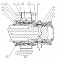
Fig. 1 is a kind of double mechanical seal formula of the utility model rotary joint structure schematic diagram
Accompanying drawing sign: 1 is that axle sleeve, 2 is that near-end housing, 3 is that proximal shaft pressure cap, 5 is that proximal shaft rim, 7 is that near-end stationary seat, 9 is that near-end stationary seal ring, 11 is that near-end rotary packing ring, 13 is that cylindroid helicalcoil compression spring, 15 is that deep groove ball bearing, 16 is elastic cylindrical pin for going out to hold rotary packing ring, 14 for going out to hold stationary seal ring, 12 for going out to hold stationary seat, 10 for going out step bearing pad, 8 for going out step bearing gland, 6 for going out end housing body, 4
Embodiment
Below in conjunction with accompanying drawing, the utility model is described in further detail:
As shown in Figure 1, a kind of double mechanical seal formula swivel joint, comprise a plurality of seal rings, axle sleeve 1, near-end housing 2, go out end housing body 3, proximal shaft pressure cap 4, go out step bearing gland 5, proximal shaft rim 6, go out step bearing pad 7, near-end stationary seat 8, go out to hold stationary seat 9, near-end stationary seal ring 10, go out to hold stationary seal ring 11, near-end rotary packing ring 12, go out to hold rotary packing ring 13, cylindroid helicalcoil compression spring 14, deep groove ball bearing 15, elastic cylindrical pin 16, described near-end housing 2 is connected with proximal shaft pressure cap 4 bolts, describedly go out end housing body 3 and go out step bearing gland 5 bolts and be connected, its feature with: described near-end housing 2 with go out end housing body 3 bolts and be connected, described near-end rotary packing ring 12 is arranged in near-end housing 2, and forms sealing with axle sleeve 1, near-end stationary seal ring 10 is tightly connected with near-end stationary seat 8, and near-end stationary seal ring 10 is fixedly installed in near-end housing 2, and is tightly connected with near-end housing 2, near-end stationary seal ring 10 and the dynamic and static sealing of near-end rotary packing ring 12 and rotary setting, describedly go out to hold rotary packing ring 13 to be arranged on out in end housing body 3, and form sealing with axle sleeve 1, described near-end rotary packing ring 12 one end are provided with proximal shaft rim 6, and the other end is provided with near-end stationary seal ring 10, go out to hold stationary seal ring 11 and go out to hold stationary seat 9 to be tightly connected, going out to hold stationary seal ring 11 to be fixedly installed on out in end housing body 3, and with go out end housing body 3 and be tightly connected, go out to hold stationary seal ring 11 and go out to hold motive sealing gyration 13, static seal and rotary setting, described cylindroid helicalcoil compression spring 14 is a plurality of, and described cylindroid helicalcoil compression spring 14 is provided with elastic cylindrical pin 16, described deep groove ball bearing 15 is located between proximal shaft pressure cap 4 and proximal shaft rim 6.

Claims (1)

1. a double mechanical seal formula swivel joint, comprise a plurality of seal rings, axle sleeve, near-end housing, go out end housing body, proximal shaft pressure cap, go out step bearing gland, proximal shaft rim, go out step bearing pad, near-end stationary seat, go out to hold stationary seat, near-end stationary seal ring, go out to hold stationary seal ring, near-end rotary packing ring, go out to hold rotary packing ring, cylindroid helicalcoil compression spring, deep groove ball bearing, elastic cylindrical pin, described near-end housing is connected with proximal shaft pressure cap bolt, describedly go out end housing body and go out step bearing gland bolt and be connected, its feature with: described near-end housing with go out end housing body bolt and be connected, described near-end rotary packing ring is arranged in near-end housing, and forms sealing with axle sleeve, described near-end rotary packing ring one end is provided with proximal shaft rim, and the other end is provided with near-end stationary seal ring, near-end stationary seal ring and near-end stationary seat are tightly connected, and near-end stationary seal ring is fixedly installed in near-end housing, and are connected with near-end housing seal, near-end stationary seal ring and the dynamic and static sealing of near-end rotary packing ring and rotary setting, describedly go out to hold rotary packing ring to be arranged on out in end housing body, and form sealing with axle sleeve, go out to hold stationary seal ring and go out to hold stationary seat to be tightly connected, going out to hold stationary seal ring to be fixedly installed on out in end housing body, and with go out end housing body and be tightly connected, go out to hold stationary seal ring and go out to hold the dynamic and static sealing of rotary packing ring and rotary setting, described cylindroid helicalcoil compression spring is a plurality of, and described cylindroid helicalcoil compression spring is provided with elastic cylindrical pin, described deep groove ball bearing is located between proximal shaft pressure cap and proximal shaft rim.
CN201320585594.8U 2013-09-20 2013-09-20 Double mechanically-sealed rotary joint Expired - Fee Related CN203463847U (en)

Priority Applications (1)

Application Number Priority Date Filing Date Title
CN201320585594.8U CN203463847U (en) 2013-09-20 2013-09-20 Double mechanically-sealed rotary joint

Applications Claiming Priority (1)

Application Number Priority Date Filing Date Title
CN201320585594.8U CN203463847U (en) 2013-09-20 2013-09-20 Double mechanically-sealed rotary joint

Publications (1)

Publication Number Publication Date
CN203463847U true CN203463847U (en) 2014-03-05

Family

ID=50176214

Family Applications (1)

Application Number Title Priority Date Filing Date
CN201320585594.8U Expired - Fee Related CN203463847U (en) 2013-09-20 2013-09-20 Double mechanically-sealed rotary joint

Country Status (1)

Country Link
CN (1) CN203463847U (en)

Cited By (1)

* Cited by examiner, † Cited by third party
Publication number Priority date Publication date Assignee Title
CN104455867A (en) * 2013-09-20 2015-03-25 滕州市宇航旋转接头制造有限公司 Double-mechanical-seal type rotary joint

Cited By (1)

* Cited by examiner, † Cited by third party
Publication number Priority date Publication date Assignee Title
CN104455867A (en) * 2013-09-20 2015-03-25 滕州市宇航旋转接头制造有限公司 Double-mechanical-seal type rotary joint

Similar Documents

Publication Publication Date Title
CN204554161U (en) A kind of right angle waves swivel joint
CN204164340U (en) Built-up piston seal arrangement
CN203463847U (en) Double mechanically-sealed rotary joint
CN202108771U (en) Sealing device structure for sewage pump
CN201202809Y (en) Stationary ring adjustable mechanical sealing device
CN201795050U (en) Magnetic fluid seal structure for thrust bearing of mixed-flow turbine
CN201013647Y (en) Mechanical sealing device of water pump for diesel engine
CN104455867A (en) Double-mechanical-seal type rotary joint
CN203730717U (en) Adjustable pinion sealing structure
CN103712015A (en) Four-point thrust angular contact type rotating joint
CN203926760U (en) A kind of bolt seal assembly
CN204942086U (en) A kind of centrifugal pump specialized high-speed swivel joint
CN202531844U (en) Bottom stirring corrugated pipe-type mechanical seal with water seal structure
CN202349212U (en) Circular clearance sealing mechanism of high temperature rotating large-diameter equipment
CN201746256U (en) Eccentric wear resistance center swivel joint for wheel crane
CN201787230U (en) Modified rotary joint
CN104421551A (en) Solar rotating joint
CN203285721U (en) Padding sealing structure of axially split pump
CN201786729U (en) Sealing device of submersible pump
CN202834062U (en) Rubber spring-type mechanical seal
CN202768852U (en) Novel dynamic-static seal device
CN203562868U (en) A device for sealing the motor shaft of a water turbine of a sea tide power generating device
CN202811480U (en) Single mechanical seal device for centrifugal pump
CN203585332U (en) Sewage pump sealing device
CN202417613U (en) Carbon-ring-type oil seal device

Legal Events

Date Code Title Description
GR01 Patent grant
GR01 Patent grant
C56 Change in the name or address of the patentee

Owner name: YUHANG AEROSPACE EQUIPMENT CO., LTD.

Free format text: FORMER NAME: TENGZHOU YUHANG ROTARY JOINT MANUFACTURING CO., LTD.

CP01 Change in the name or title of a patent holder

Address after: 277500 Shandong city of Zaozhuang province Tengzhou city wintim technology square room 26-4-1805 Tengzhou Yuhang rotary joint manufacturing Co. Ltd.

Patentee after: YUHANG AEROSPACE EQUIPMENT CO., LTD.

Address before: 277500 Shandong city of Zaozhuang province Tengzhou city wintim technology square room 26-4-1805 Tengzhou Yuhang rotary joint manufacturing Co. Ltd.

Patentee before: TENGZHOU YUHANG ROTARY JOINT MANUFACTURING CO., LTD.

CF01 Termination of patent right due to non-payment of annual fee

Granted publication date: 20140305

Termination date: 20160920

CF01 Termination of patent right due to non-payment of annual fee