CN203446070U - Induction lamp bulb - Google Patents
Induction lamp bulb Download PDFInfo
- Publication number
- CN203446070U CN203446070U CN201320482946.7U CN201320482946U CN203446070U CN 203446070 U CN203446070 U CN 203446070U CN 201320482946 U CN201320482946 U CN 201320482946U CN 203446070 U CN203446070 U CN 203446070U
- Authority
- CN
- China
- Prior art keywords
- module
- induction
- realized
- lamp bulb
- infrared induction
- Prior art date
- Legal status (The legal status is an assumption and is not a legal conclusion. Google has not performed a legal analysis and makes no representation as to the accuracy of the status listed.)
- Expired - Fee Related
Links
Images
Classifications
-
- H—ELECTRICITY
- H05—ELECTRIC TECHNIQUES NOT OTHERWISE PROVIDED FOR
- H05B—ELECTRIC HEATING; ELECTRIC LIGHT SOURCES NOT OTHERWISE PROVIDED FOR; CIRCUIT ARRANGEMENTS FOR ELECTRIC LIGHT SOURCES, IN GENERAL
- H05B47/00—Circuit arrangements for operating light sources in general, i.e. where the type of light source is not relevant
- H05B47/10—Controlling the light source
-
- H—ELECTRICITY
- H05—ELECTRIC TECHNIQUES NOT OTHERWISE PROVIDED FOR
- H05B—ELECTRIC HEATING; ELECTRIC LIGHT SOURCES NOT OTHERWISE PROVIDED FOR; CIRCUIT ARRANGEMENTS FOR ELECTRIC LIGHT SOURCES, IN GENERAL
- H05B45/00—Circuit arrangements for operating light-emitting diodes [LED]
-
- H—ELECTRICITY
- H05—ELECTRIC TECHNIQUES NOT OTHERWISE PROVIDED FOR
- H05B—ELECTRIC HEATING; ELECTRIC LIGHT SOURCES NOT OTHERWISE PROVIDED FOR; CIRCUIT ARRANGEMENTS FOR ELECTRIC LIGHT SOURCES, IN GENERAL
- H05B45/00—Circuit arrangements for operating light-emitting diodes [LED]
- H05B45/30—Driver circuits
- H05B45/37—Converter circuits
- H05B45/3725—Switched mode power supply [SMPS]
-
- H—ELECTRICITY
- H05—ELECTRIC TECHNIQUES NOT OTHERWISE PROVIDED FOR
- H05B—ELECTRIC HEATING; ELECTRIC LIGHT SOURCES NOT OTHERWISE PROVIDED FOR; CIRCUIT ARRANGEMENTS FOR ELECTRIC LIGHT SOURCES, IN GENERAL
- H05B47/00—Circuit arrangements for operating light sources in general, i.e. where the type of light source is not relevant
- H05B47/10—Controlling the light source
- H05B47/105—Controlling the light source in response to determined parameters
- H05B47/11—Controlling the light source in response to determined parameters by determining the brightness or colour temperature of ambient light
-
- Y—GENERAL TAGGING OF NEW TECHNOLOGICAL DEVELOPMENTS; GENERAL TAGGING OF CROSS-SECTIONAL TECHNOLOGIES SPANNING OVER SEVERAL SECTIONS OF THE IPC; TECHNICAL SUBJECTS COVERED BY FORMER USPC CROSS-REFERENCE ART COLLECTIONS [XRACs] AND DIGESTS
- Y02—TECHNOLOGIES OR APPLICATIONS FOR MITIGATION OR ADAPTATION AGAINST CLIMATE CHANGE
- Y02B—CLIMATE CHANGE MITIGATION TECHNOLOGIES RELATED TO BUILDINGS, e.g. HOUSING, HOUSE APPLIANCES OR RELATED END-USER APPLICATIONS
- Y02B20/00—Energy efficient lighting technologies, e.g. halogen lamps or gas discharge lamps
- Y02B20/30—Semiconductor lamps, e.g. solid state lamps [SSL] light emitting diodes [LED] or organic LED [OLED]
-
- Y—GENERAL TAGGING OF NEW TECHNOLOGICAL DEVELOPMENTS; GENERAL TAGGING OF CROSS-SECTIONAL TECHNOLOGIES SPANNING OVER SEVERAL SECTIONS OF THE IPC; TECHNICAL SUBJECTS COVERED BY FORMER USPC CROSS-REFERENCE ART COLLECTIONS [XRACs] AND DIGESTS
- Y02—TECHNOLOGIES OR APPLICATIONS FOR MITIGATION OR ADAPTATION AGAINST CLIMATE CHANGE
- Y02B—CLIMATE CHANGE MITIGATION TECHNOLOGIES RELATED TO BUILDINGS, e.g. HOUSING, HOUSE APPLIANCES OR RELATED END-USER APPLICATIONS
- Y02B20/00—Energy efficient lighting technologies, e.g. halogen lamps or gas discharge lamps
- Y02B20/40—Control techniques providing energy savings, e.g. smart controller or presence detection
Landscapes
- Circuit Arrangement For Electric Light Sources In General (AREA)
- Non-Portable Lighting Devices Or Systems Thereof (AREA)
Abstract
The utility model relates to the technical field of LED lighting, and particularly relates to an induction lamp bulb. The induction lamp bulb comprises a switching power supply module, a battery management module, a pyroelectric infrared induction module, an LED driving module and an LED light-emitting module which are electrically connected successively, wherein the battery management module is electrically connected with a convenient switch. The induction lamp bulb of the utility model has the following advantages that according to the utility model, the pyroelectric infrared induction module is combined with the lighting technology, the pyroelectric infrared induction module is used as a control source, the onoff state of a lamp is controlled automatically, the complex manual lamp turn-onturn-off operation can be avoided, the automatic turn-off function can be realized, advantages, such as high efficiency, saving energy, high sensitivity, fast response, long service life, etc., can be realized compared with a conventional lamp bulb, the advantage of easy and convenient utilization can be realized, the pyroelectric infrared induction module can be used to automatically identify day and night states, the automatic standby function can be realized in the daytime, the automatic induction function can be realized in the night, advantages of energy conservation and environment protection can be realized, and the induction lamp bulb can be widely used in places, such as stair passages, corridors, rest rooms, storage rooms, balconies, halls, etc.
Description
technical field:
The utility model relates to LED lighting technical field, refers in particular to a kind of induction bulb.
background technology:
Requirement to environmental protection is more and more higher, and just all the more so in the use field of electric energy, LED lamp is developed just under this background.LED Lantern Festival electricity is up to more than 80%, and the life-span is that common fluorescent tube obtains more than 10 times, is almost non-maintaining, and the expense of saving of getting off about half a year just can gain cost.The semi-conductor electricity light source of environmental type, light is soft, and spectroscopic pure is conducive to sight protectio and healthy, and the cold light source of 600K, to visually refrigerant impression of people, contributes to concentrate on, and raises the efficiency.LED lamp has been one of product of national green energy-saving illumination engineering focus development Just because of this, is the ideal product that replaces at present traditional fluorescent lamp.
Existing induction bulb is to use DC light current by relay, the power on/off of bulb is controlled bright light or turned off the light, and switch lamp is very large to the impact of bulb frequently, very easily damages bulb, thereby cannot meet the demand in market.
Be directed to this, so the applicant designs the utility model.
utility model content:
The purpose of this utility model is to overcome above-mentioned existing deficiency, provide a kind of daytime automatic stand-by, automatically respond to night, the induction bulb of energy-conserving and environment-protective.
The utility model is realized the technical scheme that its object adopts: this induction bulb comprises that the switch power module, battery management module, the heat that are electrically connected successively releases infrared induction module, LED driver module, LED light emitting module, and described battery management module and a Convenient switch are electrically connected.
The beneficial effects of the utility model are:
The utility model utilization heat is released infrared induction module and is combined with lighting technology, utilize heat to release infrared induction module for control source, the light on and off of automatic control lamp tool, avoided loaded down with trivial details manual control switch's lamp, the function with automatic distinguishing, compare with traditional bulb have energy-efficient, highly sensitive, response is fast, the advantages such as extra long life, easy to use, heat is released infrared induction module, automatically identification daytime and night state, daytime automatic stand-by, automatically respond to night, energy-conserving and environment-protective, can be widely used in: corridor, corridor, toilet, between storing, balcony, the places such as porch lamp.
accompanying drawing explanation:
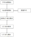
Fig. 1 is the block diagram of induction bulb.
embodiment:
Below in conjunction with specific embodiments and the drawings, the utility model is further illustrated.
As shown in Figure 1, induction bulb in the present embodiment comprises that the switch power module, battery management module, the heat that are electrically connected successively releases infrared induction module, LED driver module, LED light emitting module, described battery management module and a Convenient switch are electrically connected, wherein, switch power module provides electric power for each module.
When Convenient switch is in OFF state, battery management module does not provide power supply to release infrared induction module, LED driver module, LED light emitting module to heat; When Convenient switch is in ON state, battery management module provides power supply to release infrared induction module, LED driver module, LED light emitting module to, heat.
Battery discharge in battery management module, during minimum, closes discharge line lower than work when voltage, opens battery charging circuit.Battery charging in battery management module, when voltage reaches
While being full of value to battery, charge closing circuit.
When heat, releasing light in infrared induction module detects light intensity and opens induction output (as night) after lower than certain value, when human body to heat, release heat in infrared induction module release in the induction region of infrared induction head movable, heat is released infrared induction module will export the signal of 30 seconds to LED lamp driver module, open LED light emitting module luminous, in 30 seconds or again respond to without human body later, automatically shutdown signal (closing LED lamp) after turning on light 30 seconds, human body sensing is can repeated trigger.The light of releasing in infrared induction module when heat detects light intensity height to certain value finger lock induction output (as daytime), now in induction region, has human-induced signal, also no signal output.
The utility model utilization heat is released infrared induction module and is combined with lighting technology, utilize heat to release infrared induction module for control source, the light on and off of automatic control lamp tool, avoided loaded down with trivial details manual control switch's lamp, the function with automatic distinguishing, compare with traditional bulb have energy-efficient, highly sensitive, response is fast, the advantages such as extra long life, easy to use, heat is released infrared induction module, automatically identification daytime and night state, daytime automatic stand-by, automatically respond to night, energy-conserving and environment-protective, can be widely used in: corridor, corridor, toilet, between storing, balcony, the places such as porch lamp.
Certainly, the foregoing is only an embodiment of the present utility model, be not to limit the utility model practical range, all according to equivalence variation or modification that described in the utility model claim, structure, feature and principle are done, all should be included in the utility model claim.
Claims (1)
1. an induction bulb, is characterized in that: comprise that the switch power module, battery management module, the heat that are electrically connected successively releases infrared induction module, LED driver module, LED light emitting module, described battery management module and a Convenient switch are electrically connected.
Priority Applications (2)
| Application Number | Priority Date | Filing Date | Title |
|---|---|---|---|
| CN201320482946.7U CN203446070U (en) | 2013-08-08 | 2013-08-08 | Induction lamp bulb |
| PCT/CN2013/081574 WO2015018103A1 (en) | 2013-08-08 | 2013-08-15 | Induction light bulb |
Applications Claiming Priority (1)
| Application Number | Priority Date | Filing Date | Title |
|---|---|---|---|
| CN201320482946.7U CN203446070U (en) | 2013-08-08 | 2013-08-08 | Induction lamp bulb |
Publications (1)
| Publication Number | Publication Date |
|---|---|
| CN203446070U true CN203446070U (en) | 2014-02-19 |
Family
ID=50097078
Family Applications (1)
| Application Number | Title | Priority Date | Filing Date |
|---|---|---|---|
| CN201320482946.7U Expired - Fee Related CN203446070U (en) | 2013-08-08 | 2013-08-08 | Induction lamp bulb |
Country Status (2)
| Country | Link |
|---|---|
| CN (1) | CN203446070U (en) |
| WO (1) | WO2015018103A1 (en) |
Cited By (2)
| Publication number | Priority date | Publication date | Assignee | Title |
|---|---|---|---|---|
| CN105607506A (en) * | 2016-03-21 | 2016-05-25 | 美的集团股份有限公司 | Smart home control method and device based on user position information |
| CN111601439A (en) * | 2019-02-19 | 2020-08-28 | 珠海格力电器股份有限公司 | Electric lamp control method, electric lamp control device, storage medium and electric lamp |
Families Citing this family (1)
| Publication number | Priority date | Publication date | Assignee | Title |
|---|---|---|---|---|
| CN113966053B (en) * | 2021-11-22 | 2024-01-02 | 中电信数智科技有限公司 | Intelligent building light control method, storage medium and system |
Family Cites Families (2)
| Publication number | Priority date | Publication date | Assignee | Title |
|---|---|---|---|---|
| CN201382354Y (en) * | 2009-04-01 | 2010-01-13 | 董大海 | LED illuminating system with function of photoelectric induction of human bodies |
| CN201718078U (en) * | 2010-01-29 | 2011-01-19 | 童真 | Garden lamp infrared ray induction control system |
-
2013
- 2013-08-08 CN CN201320482946.7U patent/CN203446070U/en not_active Expired - Fee Related
- 2013-08-15 WO PCT/CN2013/081574 patent/WO2015018103A1/en active Application Filing
Cited By (3)
| Publication number | Priority date | Publication date | Assignee | Title |
|---|---|---|---|---|
| CN105607506A (en) * | 2016-03-21 | 2016-05-25 | 美的集团股份有限公司 | Smart home control method and device based on user position information |
| CN105607506B (en) * | 2016-03-21 | 2019-06-04 | 美的集团股份有限公司 | Intelligent home furnishing control method and device based on customer position information |
| CN111601439A (en) * | 2019-02-19 | 2020-08-28 | 珠海格力电器股份有限公司 | Electric lamp control method, electric lamp control device, storage medium and electric lamp |
Also Published As
| Publication number | Publication date |
|---|---|
| WO2015018103A1 (en) | 2015-02-12 |
Similar Documents
| Publication | Publication Date | Title |
|---|---|---|
| CN202769518U (en) | Solar light-emitting diode (LED) lamp | |
| CN202818683U (en) | Intelligent LED lamp | |
| CN203446070U (en) | Induction lamp bulb | |
| CN204559223U (en) | A kind of multifunctional emergency light | |
| CN103517524B (en) | Led emergency controller | |
| CN201057410Y (en) | Solar acousto-optic control and human body inducing corridor lamp | |
| CN202392666U (en) | Emergency lamp | |
| CN205336608U (en) | Light emitting diode (LED) constant -current driving power supply | |
| CN205584588U (en) | Novel corridor lighting system | |
| CN101039043A (en) | Solar energy lighting emergency system | |
| CN204460059U (en) | Solar energy charging type LED lamp | |
| CN203562828U (en) | Fire-fighting emergency lighting energy-saving system | |
| CN203023889U (en) | Light emitting diode (LED) lamp with human body induction device | |
| CN202406347U (en) | Infrared control LED (Light-emitting Diode) energy-saving lamp | |
| CN202652637U (en) | Light-controlled energy-saving switch | |
| CN206904631U (en) | The emergent intelligent bulb lamp of one kind | |
| CN201661977U (en) | Novel household solar LED illumination system | |
| CN203708597U (en) | LED indoor lighting control system | |
| CN208046987U (en) | A kind of energy saving induction circuit for lamp of dual power supply | |
| CN203027557U (en) | Intelligent LED (Light Emitting Diode) illumination energy-saving control system | |
| CN203177102U (en) | Lamp | |
| CN104637127A (en) | Access control machine with infrared induction lighting lamp | |
| CN205793557U (en) | A kind of indoor lamp intelligent energy-saving control device | |
| CN202043330U (en) | Power supply management circuit of lighting system | |
| CN205622917U (en) | Energy -conserving circuit of light -operated LED street lamp |
Legal Events
| Date | Code | Title | Description |
|---|---|---|---|
| C14 | Grant of patent or utility model | ||
| GR01 | Patent grant | ||
| CF01 | Termination of patent right due to non-payment of annual fee | ||
| CF01 | Termination of patent right due to non-payment of annual fee |
Granted publication date: 20140219 Termination date: 20180808 |