CN203442972U - Device for utilizing tail end of indoor air conditioner and filter elements to treat air - Google Patents
Device for utilizing tail end of indoor air conditioner and filter elements to treat air Download PDFInfo
- Publication number
- CN203442972U CN203442972U CN201320519204.7U CN201320519204U CN203442972U CN 203442972 U CN203442972 U CN 203442972U CN 201320519204 U CN201320519204 U CN 201320519204U CN 203442972 U CN203442972 U CN 203442972U
- Authority
- CN
- China
- Prior art keywords
- air
- air conditioner
- shell
- tail end
- room
- Prior art date
- Legal status (The legal status is an assumption and is not a legal conclusion. Google has not performed a legal analysis and makes no representation as to the accuracy of the status listed.)
- Expired - Lifetime
Links
Images

Abstract
The utility model discloses a device for utilizing the tail end of an indoor air conditioner and filter elements to treat air. The device is composed of the tail end of the indoor air conditioner, the filter elements, a filter fan and a shell, wherein the tail end of the indoor air conditioner comprises an air conditioner fan, a heat exchanger, an air supply shutter and an air conditioner shell. The filter elements and the filter fan are fixed into the shell. Air intakes and openings are formed in the shell. An air inlet is formed in the air conditioner shell. An air outlet of the filter fan is communicated with the air inlet of the tail end of the indoor air conditioner. The air conditioner fan and the heat exchanger are fixed into the air conditioner shell. The air supply shutter is installed on the air conditioner shell. According to the device, the tail end of the indoor air conditioner and the efficient filter elements are combined together to treat air, and the device has the advantages of being good in filter purification effect, low in cost, simple and reliable in system, and capable of protecting the tail end of the indoor air conditioner from pollution.
Description
Technical field
The utility model relates to a kind of air purifying process, relates in particular to a kind of device that utilizes room air end and filtering core to process air.
Background technology
Conventional room air is processed end, as VRV indoor set, split-type air conditioner indoor set and fan coil etc., do not possess high-efficiency filtering and purifying function, along with people more and more pay close attention to air quality, various indoor air-purifiers arise at the historic moment, but on market, various indoor air-purifier filter efficiencies are low, general to the filter efficiency of PM2.5 lower than 70%, simultaneously, various indoor air-purifiers are compared with indoor apparatus of air conditioner, and because air quantity is less, air is difficult for diffusion and causes forming local circulation.
Send interior function to combine the filtering function of indoor air-purifier and the long distance of indoor apparatus of air conditioner, adopt high efficiency filter core body simultaneously, will greatly improve indoor air purification efficiency; In addition, high efficiency filter core body forms dust stratification by the heat exchanger that effectively prevents room air end and avoids producing the harmful substances such as mould, the heat transfer effect that also can obtain.
Summary of the invention
The purpose of this utility model is for the deficiencies in the prior art, and a kind of device that utilizes room conditioning end and filtering core to process air is provided.
The purpose of this utility model is achieved through the following technical solutions: a kind of device that utilizes room conditioning end and filtering core to process air, and described device is comprised of room conditioning end, filtering core, filtration blower fan and shell; Wherein, described room conditioning end comprises air-conditioning draught fan, heat exchanger, air-supply blinds and air conditioner housing; Described filtering core and filtration blower fan are fixed in the enclosure, have air intlet and opening on shell, have air inlet in air conditioner housing; The air outlet that filters blower fan is communicated with the air inlet of room conditioning end, and air-conditioning draught fan and heat exchanger are fixed in air conditioner housing, and air-supply blinds is arranged in air conditioner housing.
Further, described shell be positioned at room conditioning end under.
Further, described shell and air conditioner housing are integrally formed.
The beneficial effects of the utility model are that the utility model is combined room air end and is processed air with high efficiency filter core body, have filtration, purification effective, effectively protects the features such as room air end is not contaminated, and cost is low, and system is simple and reliable.
Accompanying drawing explanation
Fig. 1 is principle schematic of the present utility model;
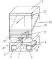
Fig. 2 is structural representation of the present utility model.
The specific embodiment
As shown in Figure 1, it is as follows that the utility model utilizes room conditioning end and filtering core to process the square ratio juris of air: one room air A1 is purified through filtering core 2 under driving with the supporting filtration blower fan 1 of filtering core 2, then enter the air-conditioning draught fan 31 of room conditioning end 3 together with another gang of room air A2, under the driving of air-conditioning draught fan 31, room air through room conditioning end 3 is processed end, as VRV indoor set, split-type air conditioner indoor set and fan coil etc., finally by the air-supply blinds 33 of crossing room conditioning end 3, with certain wind speed, send long distance and be transported to whole room.The air-supply blinds 33 of room conditioning end 3 generally has oscillating function, utilizes it to swing, can be so that air-supply be evenly distributed to room, and long distance is blown and is swung air-supply, will greatly improve indoor air purification efficiency.
Room air is processed end, can be VRV indoor set, and split-type air conditioner indoor set and fan coil etc., be connected with outdoor host computer (not shown in figure 1).One side of the heat exchanger 32 in Fig. 1 is room air, and opposite side is refrigeration working medium, as freon, or water, salt solution etc.
When indoor need to carry out air conditioning time, as refrigeration, when heating or dehumidifying, when room air A1 and room air A2 process heat exchanger 32, its enthalpy changes, air handling process shown in Fig. 1 comprises air-conditioning and air cleaning, and when indoor need not carry out air conditioning time, room air A1 and room air A2 are during through heat exchanger 32, its enthalpy is constant, and the air handling process shown in Fig. 1 is only air cleaning.
In Fig. 1, the flow of room air A1 is generally the 10-30% of room air A2 flow.
In Fig. 1, filtering core 2 adopts high efficiency filter material, as polytetrafluoroethylene (PTFE), is suitable for water and directly cleans, and the purification efficiency of PM2.5 is greater than to 90%.
In Fig. 1, filtering core 2 filtering material used is suitable for water and directly cleans.
As shown in Figure 2, a kind of device of realizing said method, is comprised of room conditioning end 3, filtering core 2, filtration blower fan 1 and shell 4 etc.Room conditioning end 3 comprises air-conditioning draught fan 31, heat exchanger 32, air-supply blinds 33, air conditioner housing 34, air inlet 35 etc., filters the air outlet of blower fan 1 and the air inlet 35 of room conditioning end 3 and is communicated with.On shell 4, have air intlet 5 and opening 6.
Described shell 4 be positioned at room conditioning end 3 under, can be integrated with air conditioner housing 34, like this can be cost-saving, also help this device filtration fraction and room conditioning end 3 and be integrated.
Described filtering core 2 and filtration blower fan 3 are fixed in shell 4.
For the ease of cleaning, filtering core 2 can be directly from opening 6 dial-outs of shell 4, and without utilizing specific purpose tool, as screwdriver etc.
Filtering core 2 adopts high efficiency filter material, and the purification efficiency of PM2.5 is greater than to 90%.
The control of this device filtration fraction and room conditioning end 3 also can be controlled by same controller, as filtered blower fan 1 in Fig. 2, can be controlled by the controller of room conditioning end 3.
Claims (3)
1. utilize room conditioning end and filtering core to process a device for air, it is characterized in that, described device is comprised of room conditioning end, filtering core, filtration blower fan and shell; Wherein, described room conditioning end comprises air-conditioning draught fan, heat exchanger, air-supply blinds and air conditioner housing; Described filtering core and filtration blower fan are fixed in the enclosure, have air intlet and opening on shell, have air inlet in air conditioner housing; The air outlet that filters blower fan is communicated with the air inlet of room conditioning end, and air-conditioning draught fan and heat exchanger are fixed in air conditioner housing, and air-supply blinds is arranged in air conditioner housing.
2. device according to claim 1, is characterized in that, described shell be positioned at room conditioning end under.
3. device according to claim 1, is characterized in that, described shell and air conditioner housing are integrally formed.
Priority Applications (1)
| Application Number | Priority Date | Filing Date | Title |
|---|---|---|---|
| CN201320519204.7U CN203442972U (en) | 2013-08-25 | 2013-08-25 | Device for utilizing tail end of indoor air conditioner and filter elements to treat air |
Applications Claiming Priority (1)
| Application Number | Priority Date | Filing Date | Title |
|---|---|---|---|
| CN201320519204.7U CN203442972U (en) | 2013-08-25 | 2013-08-25 | Device for utilizing tail end of indoor air conditioner and filter elements to treat air |
Publications (1)
| Publication Number | Publication Date |
|---|---|
| CN203442972U true CN203442972U (en) | 2014-02-19 |
Family
ID=50094024
Family Applications (1)
| Application Number | Title | Priority Date | Filing Date |
|---|---|---|---|
| CN201320519204.7U Expired - Lifetime CN203442972U (en) | 2013-08-25 | 2013-08-25 | Device for utilizing tail end of indoor air conditioner and filter elements to treat air |
Country Status (1)
| Country | Link |
|---|---|
| CN (1) | CN203442972U (en) |
Cited By (2)
| Publication number | Priority date | Publication date | Assignee | Title |
|---|---|---|---|---|
| CN103438506A (en) * | 2013-08-25 | 2013-12-11 | 叶立英 | Method and device for treating air through indoor air conditioning terminal and filter element |
| CN110285484A (en) * | 2019-06-26 | 2019-09-27 | 狄风君 | A kind of fan coiled heat-exchanger |
-
2013
- 2013-08-25 CN CN201320519204.7U patent/CN203442972U/en not_active Expired - Lifetime
Cited By (3)
| Publication number | Priority date | Publication date | Assignee | Title |
|---|---|---|---|---|
| CN103438506A (en) * | 2013-08-25 | 2013-12-11 | 叶立英 | Method and device for treating air through indoor air conditioning terminal and filter element |
| CN103438506B (en) * | 2013-08-25 | 2015-12-09 | 叶立英 | Utilize the method and apparatus of room conditioning end and filtering core process air |
| CN110285484A (en) * | 2019-06-26 | 2019-09-27 | 狄风君 | A kind of fan coiled heat-exchanger |
Similar Documents
| Publication | Publication Date | Title |
|---|---|---|
| CN204460487U (en) | Air purifier | |
| CN202056986U (en) | Integrated air supply device and air handling system for hospital unit ceilings | |
| CN205783540U (en) | Internal-external double circulation New-air purifying system | |
| CN203586421U (en) | Water film type air cleaner with heat exchanger | |
| CN107062457A (en) | A kind of fresh air and the devices and methods therefor of room air synchronous purification | |
| CN105444325A (en) | Fresh air purification system with axial-flow fans | |
| CN203442972U (en) | Device for utilizing tail end of indoor air conditioner and filter elements to treat air | |
| CN203731590U (en) | Double-gradient comfortability purifying air conditioning unit | |
| CN204240525U (en) | Single channel accumulation of energy aeration device and indoor air cleaner | |
| CN201251248Y (en) | Cleaning operating room with an FFU and a wind processing system thereof | |
| CN203628862U (en) | Fresh air preparing machine installed outdoors and used for optimizing indoor air quality | |
| CN204421251U (en) | Filter humidifying type Fresh air handling units | |
| CN104132396A (en) | Carbon nanofiber electric field dust particle gathering and air purifying device | |
| CN203671765U (en) | Household air purification interchanger | |
| CN204987304U (en) | Energy -saving new trend clarifier | |
| CN103438506B (en) | Utilize the method and apparatus of room conditioning end and filtering core process air | |
| CN104214883A (en) | Fresh air purifier | |
| CN204678525U (en) | A kind of Novel air purifier group | |
| CN203561005U (en) | A medical purifying air handling unit | |
| CN103090480B (en) | Active window type energy conversion and ventilation device | |
| CN202133047U (en) | Novel full-heat recovery type fan set | |
| CN201973840U (en) | Fresh air ventilator | |
| CN204084732U (en) | Fresh air purifier | |
| CN103644599A (en) | Household air purification exchanger | |
| CN204421252U (en) | A kind of purification fan case |
Legal Events
| Date | Code | Title | Description |
|---|---|---|---|
| C14 | Grant of patent or utility model | ||
| GR01 | Patent grant | ||
| AV01 | Patent right actively abandoned |
Granted publication date: 20140219 Effective date of abandoning: 20151209 |
|
| C25 | Abandonment of patent right or utility model to avoid double patenting |