CN203442384U - Mining quick connection device for water pipe and air pipe - Google Patents
Mining quick connection device for water pipe and air pipe Download PDFInfo
- Publication number
- CN203442384U CN203442384U CN201320551667.1U CN201320551667U CN203442384U CN 203442384 U CN203442384 U CN 203442384U CN 201320551667 U CN201320551667 U CN 201320551667U CN 203442384 U CN203442384 U CN 203442384U
- Authority
- CN
- China
- Prior art keywords
- spherical
- connector
- groove
- connection device
- quick connection
- Prior art date
- Legal status (The legal status is an assumption and is not a legal conclusion. Google has not performed a legal analysis and makes no representation as to the accuracy of the status listed.)
- Expired - Fee Related
Links
Images


Landscapes
- Flanged Joints, Insulating Joints, And Other Joints (AREA)
Abstract
本实用新型公开了一种矿用水管、风管快速连接装置,包括球形槽口腔连接件、球形连接件、卡扣、两个沟槽式管接件几部分组成,其中球形连接件的顶端嵌装在球形槽口腔连接件的内部,卡扣安装在球形槽口腔连接件的外壁面上,两个沟槽式连接件分别卡箍固定在球形槽口腔连接件和球形连接件的两端。本实用新型提供的矿用水管、风管快速连接装置安装简单、密封性好,稳定性强,对于矿下复杂的生产环境,具有较好的应用效果。
The utility model discloses a quick connection device for mine water pipes and air pipes. Installed inside the spherical groove mouth connector, the buckle is installed on the outer wall surface of the spherical groove mouth connector, and the two grooved connectors are clamped and fixed on the spherical groove mouth connector and the two ends of the spherical connector respectively. The mine water pipe and air pipe quick connection device provided by the utility model has the advantages of simple installation, good sealing performance and strong stability, and has a good application effect for the complex production environment under the mine.
Description
技术领域technical field
本实用新型涉及一种水管、风管的连接装置,特别是涉及一种矿用水管、风管快速连接装置,适用于矿业工程、农业、市政工程等领域的水管、风管快速连接。The utility model relates to a connection device for water pipes and air pipes, in particular to a quick connection device for mine water pipes and air pipes, which is suitable for quick connection of water pipes and air pipes in mining engineering, agriculture, municipal engineering and other fields.
背景技术Background technique
在矿用水管、风管的连接方法中,多采用沟槽式管接件将水管、风管的两端进行对接,以实现管道的连接畅通,但由于沟槽式管接件的结构设计因素,其存在以下不足之处:1、沟槽式管接件存在密封不严,漏水、漏气的情况;2、沟槽式管接件耐腐蚀性较差,在矿下复杂的生产环境下使用寿命较短;3、在大口径管道的连接过程中,存在压力水、气冲击塑胶层,导致钢塑分离使内衬塑胶移位的现象,容易诱发管道堵塞的危险;4、不能快速实现管道的连通与拆卸。In the connection method of mine water pipes and air pipes, grooved pipe joints are often used to connect the two ends of the water pipes and air pipes to achieve smooth connection of the pipes. However, due to the structural design factors of the grooved pipe joints , which has the following deficiencies: 1. The grooved pipe joints are not tightly sealed, leaking, and leaking; 2. The grooved pipe joints have poor corrosion resistance, and they can be used in complex production environments under the mine. The service life is short; 3. During the connection process of large-diameter pipes, there is pressure water and air impacting the plastic layer, which leads to the separation of steel and plastic and the displacement of the lining plastic, which easily induces the risk of pipe blockage; 4. It cannot be realized quickly Pipe connection and disassembly.
本实用新型针对以上缺陷加以改进,采用了一种水管、风管连接密封的最新方法,可使用在矿井生产系统、农业及市政工程等领域,实现了管道的快速连接安装,同时在连接装置的接口处进行了密封处理,确保了在使用过程中不泄露管内液体或气体,提高了矿用水管、风管连接的稳定性和密封性。The utility model improves on the above defects and adopts a newest method of connecting and sealing water pipes and air pipes, which can be used in the fields of mine production systems, agriculture and municipal engineering, etc., and realizes the quick connection and installation of pipelines. The interface is sealed to ensure that the liquid or gas in the pipe does not leak during use, and improves the stability and sealing of the mine water pipe and air pipe connection.
发明内容Contents of the invention
本实用新型的目的是为了解决矿井生产系统中的水管、风管安装拆卸困难,易漏液漏气、耐腐蚀性较差等问题,提出了一种矿用水管、风管的快速连接装置。The purpose of this utility model is to solve the problems of difficult installation and disassembly of water pipes and air pipes in the mine production system, easy leakage of liquid and air, poor corrosion resistance, etc., and proposes a quick connection device for mine water pipes and air pipes.
为了达到上述目的,本实用新型的具体实施方案是:In order to achieve the above object, the specific embodiment of the utility model is:
一种矿用水管、风管快速连接装置,包括球形槽口腔连接件、球形连接件、卡扣和两个沟槽式管接件几部分组成。其特征在于:球形连接件的顶端嵌装在球形槽口腔连接件的槽口腔凹槽内,卡扣安装在球形槽口腔连接件的外壁面上,两个沟槽式管接件分别卡箍固定在球形槽口腔连接件和球形连接件的两端。The utility model relates to a quick connection device for mine water pipes and air pipes. It is characterized in that: the top of the spherical connector is embedded in the groove of the groove of the spherical groove mouth connector, the buckle is installed on the outer wall of the spherical groove mouth connector, and the two grooved pipe joints are respectively clamped and fixed At both ends of the ball socket mouth connector and the ball connector.
所述球形槽口腔连接件严格遵照《液压快速接头尺寸和要求》(GB/T5860-2003)、《结构用不锈钢无缝钢管》(GB/T14975-2012)的参数设计,为一中空的不锈钢金属构件,球形槽口腔连接件的一端为球形结构,中间设有与沟槽式管接件内部凹槽相匹配的凸台,另一端外表面环向分布有倒锯齿状凹槽。所述球形结构中部有一个与球形连接件顶端相匹配的槽口腔凹槽,在凹槽的表面上均匀喷涂有一层隔水塑性膜;The spherical groove mouth connector is designed in strict accordance with the parameters of "Hydraulic Quick Connect Dimensions and Requirements" (GB/T5860-2003) and "Stainless Steel Seamless Steel Tube for Structural Use" (GB/T14975-2012), and is a hollow stainless steel metal One end of the spherical groove mouth connector is a spherical structure, with a boss matching the inner groove of the grooved pipe joint in the middle, and inverted serrated grooves distributed circumferentially on the outer surface of the other end. The middle part of the spherical structure has a groove mouth groove matching the top of the spherical connector, and a layer of water-proof plastic film is evenly sprayed on the surface of the groove;
所述球形连接件为一中空的不锈钢金属构件,连接件的一端为与球形槽口腔连接件内部槽口腔凹槽相匹配的球形结构,球形结构的表面均匀喷涂有一层隔水塑性膜,连接件的中部设有与沟槽式管接件内部凹槽相匹配的凸台,另一端外表面环向分布有倒锯齿状凹槽;The spherical connector is a hollow stainless steel metal member, and one end of the connector is a spherical structure that matches the groove of the inner groove of the spherical groove mouth connector. The surface of the spherical structure is evenly sprayed with a layer of water-proof plastic film, and the connector The middle part is provided with a boss matching the internal groove of the grooved pipe fitting, and the outer surface of the other end is circumferentially distributed with inverted serrated grooves;
所述沟槽式管接件严格遵照《自动喷水灭火系统第11部分:沟槽式管接件》(GB5135.11-2006)的参数设计,包括拼合式卡箍件、橡胶密封圈和起紧固所用的螺栓、螺母几部分组成。所述拼合式卡箍件内部有与球形槽口腔连接件和球形连接件中部凸台相匹配的凹槽;所述螺栓的结构和尺寸符合GB/T8262的参数规定,机械性能不低于GB/T3098.1中规定的8.8级要求,同时螺栓的外表面进行的镀锌防腐蚀处理;所述螺母的机械性能符合GB/T3098.2中规定,同时在螺母的外表面进行的镀锌防腐蚀处理;The grooved pipe fittings are designed in strict accordance with the parameters of "Automatic Sprinkler System Part 11: Grooved Pipe Fittings" (GB5135.11-2006), including split clamps, rubber seals and lifters. The bolts and nuts used for fastening are composed of several parts. There is a groove inside the split-type clamp that matches the spherical groove cavity connector and the middle boss of the spherical connector; the structure and size of the bolt comply with the parameters specified in GB/T8262, and the mechanical properties are not lower than GB/T8262. The 8.8 grade requirements specified in T3098.1, and the outer surface of the bolt is galvanized for anti-corrosion treatment; the mechanical properties of the nut meet the requirements specified in GB/T3098.2, and the outer surface of the nut is galvanized for anti-corrosion treatment deal with;
所述卡扣为一端具有圆孔的金属杆件,通过螺栓固定在球形槽口腔连接件的外表面上。The buckle is a metal rod with a round hole at one end, which is fixed on the outer surface of the spherical groove-mouth connector by bolts.
本实用新型所提供的矿用水管、风管快速连接装置,有利于单人独立操作,实现了管道的快速连接安装。同时,在连接装置的接口处进行了密封处理,确保了连接装置的稳定性和密封性,提高了生产效率。The quick connection device for mine water pipes and air pipes provided by the utility model is conducive to independent operation by a single person, and realizes quick connection and installation of pipelines. At the same time, sealing treatment is carried out at the interface of the connecting device, which ensures the stability and tightness of the connecting device and improves the production efficiency.
附图说明Description of drawings
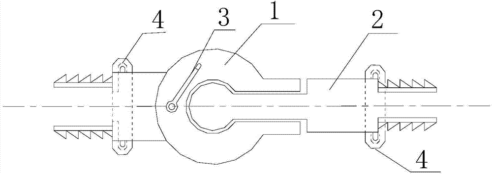
图1为本实用新型矿用水管、风管快速连接装置的整体结构示意图;Fig. 1 is the overall structure schematic diagram of the utility model mine water pipe, air pipe quick connection device;
图2为本实用新型的球形槽口腔连接件的结构示意图;Fig. 2 is a schematic structural view of the spherical groove oral connector of the present invention;
图3为本实用新型的球形连接件结构示意图;Fig. 3 is a schematic structural diagram of a spherical connector of the present invention;
图4为本实用新型的沟槽式管接件结构示意图;Fig. 4 is a structural schematic diagram of a grooved pipe connector of the present invention;
图5为本实用新型的卡扣结构示意图。Fig. 5 is a schematic diagram of the buckle structure of the present invention.
图中符号说明如下:The symbols in the figure are explained as follows:
1-球形槽口腔连接件、2-球形连接件、3-卡扣、4-沟槽式管接件、5-球形结构、6-凸台、7-倒锯齿状凹槽、8-槽口腔凹槽、9-隔水塑形膜、10-球形结构、11-拼合式卡箍件、12-橡胶密封圈、13-螺栓、14-螺母、15-凹槽、16-圆孔。1-spherical groove mouth connector, 2-spherical connector, 3-buckle, 4-groove pipe joint, 5-spherical structure, 6-boss, 7-inverted serrated groove, 8-groove mouth Groove, 9-water-proof plastic film, 10-spherical structure, 11-split clamp, 12-rubber sealing ring, 13-bolt, 14-nut, 15-groove, 16-round hole.
具体实施方式Detailed ways
为了更好地理解本实用新型,让工程技术人员快速的掌握矿用水管、风管快速连接装置的使用方法,下面结合附图对本实用新型做进一步的描述。In order to better understand the utility model and allow engineering and technical personnel to quickly grasp the use method of the mine water pipe and air pipe quick connection device, the utility model will be further described below in conjunction with the accompanying drawings.
如图1所示,一种矿用水管、风管快速连接装置,包括球形槽口腔连接件1、球形连接件2、卡扣3和两个沟槽式管接件4几部分组成。其特征在于:球形连接件2的顶端嵌装在球形槽口腔连接件1的内部,卡扣3安装在球形槽口腔连接件1的外壁面上,两个沟槽式管接件4分别卡箍固定在球形槽口腔连接件1和球形连接件2的两端。As shown in FIG. 1 , a mine water pipe and air pipe quick-connect device includes a spherical groove mouth connector 1 , a spherical connector 2 ,
所述球形槽口腔连接件1如图2所示,为一中空的不锈钢金属构件,球形槽口腔连接件1的一端为球形结构5,中间设有与沟槽式管接件4内部凹槽15相匹配的凸台6,另一端外表面环向分布有倒锯齿状凹槽7。所述球形结构5中部有一个与球形连接件2顶端相匹配的槽口腔凹槽8,在凹槽的表面上均匀喷涂有一层隔水塑性膜9。The spherical groove mouth connector 1 is a hollow stainless steel metal member as shown in FIG. The outer surface of the other end of the matching
所述球形连接件2如图3所示,为一中空的不锈钢金属构件,连接件的一端为与球形槽口腔连接件1内部槽口腔凹槽8相匹配的球形结构10,球形结构10的表面均匀喷涂有一层隔水塑性膜9,连接件的中部设有与沟槽式管接件4内部凹槽15相匹配的凸台6,另一端外表面环向分布有倒锯齿状凹槽7。The spherical connector 2 is a hollow stainless steel metal member as shown in FIG. A layer of water-proof
所述沟槽式管接件4如图4所示,包括拼合式卡箍件11、橡胶密封圈12和起紧固所用的螺栓13、螺母14几部分组成。所述拼合式卡箍件11内部有与球形槽口腔连接件1和球形连接件2中部凸台6相匹配的凹槽15,同时螺栓13、螺母14的外表面进行的镀锌防腐蚀处理。The grooved pipe joint 4 is shown in FIG. 4 , and includes a
如图5所示,所述卡扣3为一端具有圆孔16的金属杆件,通过螺栓固定在球形槽口腔连接件1的外表面上。As shown in FIG. 5 , the
本实用新型一种矿用水管、风管快速连接装置的具体使用方法如下:The concrete usage method of a mine water pipe and air pipe quick connection device of the utility model is as follows:
首先,将矿用水管、风管快速连接装置的球形槽口腔连接件1和球形连接件2的倒锯齿状凹槽7端安装在将要进行连通的两段管道之上,并将橡胶密封圈12嵌装在连接接口处;紧接着,将拼合式卡箍件11的内部凹槽15置于球形槽口腔连接件1和球形连接件2的中部凸台6上,同时调节卡箍件的位置,使其外边沿均匀的覆压在橡胶密封圈12之上,然后通过螺栓13、螺母14固定;最后,将球形连接件2的顶端嵌装在球形槽口腔连接件1的槽口腔凹槽8内,扭动卡扣3,使球形连接件2紧固在槽口腔连接件1的槽口腔凹槽8内,实现管道的连通。First, install the spherical groove mouth connector 1 of the mine water pipe and the quick connection device of the air pipe and the inverted
在对本实用新型一种矿用水管、风管快速连接装置进行拆卸时,仅需将卡扣3从球形连接件2的上部移开,然后将球形连接件2从球形槽口腔连接件1的槽口腔凹槽8内取出即可。When disassembling a mine water pipe and air pipe quick connecting device of the present invention, it is only necessary to remove the
Claims (5)
Priority Applications (1)
| Application Number | Priority Date | Filing Date | Title |
|---|---|---|---|
| CN201320551667.1U CN203442384U (en) | 2013-09-06 | 2013-09-06 | Mining quick connection device for water pipe and air pipe |
Applications Claiming Priority (1)
| Application Number | Priority Date | Filing Date | Title |
|---|---|---|---|
| CN201320551667.1U CN203442384U (en) | 2013-09-06 | 2013-09-06 | Mining quick connection device for water pipe and air pipe |
Publications (1)
| Publication Number | Publication Date |
|---|---|
| CN203442384U true CN203442384U (en) | 2014-02-19 |
Family
ID=50093440
Family Applications (1)
| Application Number | Title | Priority Date | Filing Date |
|---|---|---|---|
| CN201320551667.1U Expired - Fee Related CN203442384U (en) | 2013-09-06 | 2013-09-06 | Mining quick connection device for water pipe and air pipe |
Country Status (1)
| Country | Link |
|---|---|
| CN (1) | CN203442384U (en) |
Cited By (1)
| Publication number | Priority date | Publication date | Assignee | Title |
|---|---|---|---|---|
| CN104668227A (en) * | 2015-02-05 | 2015-06-03 | 新疆克拉玛依市采丰实业有限责任公司 | Anti-separation fluid high-pressure spraying gun |
-
2013
- 2013-09-06 CN CN201320551667.1U patent/CN203442384U/en not_active Expired - Fee Related
Cited By (2)
| Publication number | Priority date | Publication date | Assignee | Title |
|---|---|---|---|---|
| CN104668227A (en) * | 2015-02-05 | 2015-06-03 | 新疆克拉玛依市采丰实业有限责任公司 | Anti-separation fluid high-pressure spraying gun |
| CN104668227B (en) * | 2015-02-05 | 2017-04-05 | 新疆克拉玛依市采丰实业有限责任公司 | Anticreep fluid high-pressure spray gun |
Similar Documents
| Publication | Publication Date | Title |
|---|---|---|
| CN207178944U (en) | The card pressure water purification thin-wall stainless steel pipe fitting of one kind three | |
| CN204372392U (en) | General pipe network with low or medium pressure quick union | |
| CN206112328U (en) | FRP pipe and contactless connecting device of steel storage tank | |
| CN203549191U (en) | Union reducing joint | |
| CN203517102U (en) | Flexible pipe connector | |
| CN103292094A (en) | Diameter variable glass fiber pipeline | |
| CN204284760U (en) | A kind of three-limb tube part | |
| CN202577554U (en) | Polypropylene mute drainpipe fitting provided with double buckle type threaded connection head | |
| CN202252451U (en) | Female threaded union | |
| CN110701400A (en) | Quick self-sealing's pipe joint | |
| CN211059553U (en) | Reducing thin-wall stainless steel pipe connecting structure | |
| CN203131317U (en) | Pipeline joint for maintenance | |
| CN104455871B (en) | A kind of three-limb tube part | |
| CN202176844U (en) | Flexible pipe fitting | |
| CN203336088U (en) | Pipeline quick connector | |
| CN201723883U (en) | Pipe fitting quick change connection device | |
| CN202065592U (en) | Press-fitting constant-diameter pipe fitting bend | |
| CN200949715Y (en) | A pipe connection device | |
| CN205579007U (en) | Fixing device that is connected with metal pipe fittings is managed to winding arrangement wall | |
| CN206419581U (en) | A kind of PVC shape tubes | |
| CN202074169U (en) | Press fitting pipe elbow | |
| CN204879199U (en) | Modular heavy -calibre threading steel pipe and nylon corrugated pipe rapid connection means | |
| CN221075613U (en) | Novel water supply pipeline | |
| CN202501127U (en) | Improved pipeline connecting structure | |
| CN201982731U (en) | Dual-purpose check valve |
Legal Events
| Date | Code | Title | Description |
|---|---|---|---|
| C14 | Grant of patent or utility model | ||
| GR01 | Patent grant | ||
| CF01 | Termination of patent right due to non-payment of annual fee |
Granted publication date: 20140219 Termination date: 20140906 |
|
| EXPY | Termination of patent right or utility model |