CN203411374U - Electrodialysis device with electrode junction boxes on backs of compaction plates - Google Patents
Electrodialysis device with electrode junction boxes on backs of compaction plates Download PDFInfo
- Publication number
- CN203411374U CN203411374U CN201320514532.8U CN201320514532U CN203411374U CN 203411374 U CN203411374 U CN 203411374U CN 201320514532 U CN201320514532 U CN 201320514532U CN 203411374 U CN203411374 U CN 203411374U
- Authority
- CN
- China
- Prior art keywords
- electrodialysis
- pressure strip
- electrode
- water
- connection box
- Prior art date
- Legal status (The legal status is an assumption and is not a legal conclusion. Google has not performed a legal analysis and makes no representation as to the accuracy of the status listed.)
- Expired - Lifetime
Links
Images


Landscapes
- Separation Using Semi-Permeable Membranes (AREA)
- Water Treatment By Electricity Or Magnetism (AREA)
Abstract
The utility model relates to an electrodialysis device, in particular relates to an electrodialysis device with electrode junction boxes on the backs of compaction plates and mainly solves the technical problems that a manufacturing technology for electrode plates is complicated, electricity is easily leaked in a working process, a working safety area for an operator is small and the like because electrodes of an existing electrodialysis device are arranged on the side surfaces of the electrode plates in the prior art. The electrodialysis device comprises a bracket, wherein a film stack communicated with a fresh water chamber, an electrode chamber and a concentrated water chamber through pipelines is arranged on the bracket; an electrodialysis fresh water inlet, an electrodialysis fresh water outlet, an electrodialysis concentrated water inlet and an electrodialysis concentrated water outlet are formed in the film stack; the electrode chamber is connected with an electrodialysis electrode water inlet; the electrodialysis electrode water inlet is connected with an electrodialysis electrode water outlet through a circulation pipeline; the compaction plates are respectively arranged on two sides of the film stack; the electrode junction boxes are arranged on the backs of the compaction plates.
Description
Technical field
The utility model relates to a kind of electrodialysis unit electrodialysis unit, especially relates to the electrodialysis unit of a kind of pressure strip back design electrode connection box.
Background technology
Electrodialysis is under the effect of applying direct current electric field, makes the yin, yang ion in water do orientation movement, by the selection perviousness of yin, yang ion-exchange membrane, produces required deionized water.General electrodialysis appts is mainly comprised of membrane stack and water pipe, and the water in tank is entered to membrane stack by the mode of pressurizeing from water pipe.Chinese patent discloses a kind of electrolysis-electrodialysis device (Granted publication number: CN 101545114), this device at least contains an electrolysis-electrodialysis cell and gripping unit, each electrolysis-electrodialysis cell contains feeding liquid joint, out-feed liquid joint, front shroud, back shroud, positive plate, negative plate, front gasket seal, rear gasket seal, ion selectivity see through film and anode electrode post and cathodic electricity pole; At front shroud and back shroud inside, be respectively equipped with a cavity, positive plate and negative plate are placed in respectively front shroud and back shroud cavity, or positive plate and negative plate are placed in respectively the cavity of back shroud and front shroud; Ion selectivity sees through film and by front gasket seal and rear gasket seal and front shroud cavity and back shroud cavity, forms former and later two chambers respectively; On positive plate and negative plate, all have pole plate threaded hole, on front shroud and back shroud, all have the cover board hole aligning with pole plate threaded hole, anode electrode post and cathodic electricity pole are entered in front shroud chamber and back shroud chamber and with the pole plate threaded hole interlock on battery lead plate and are screwed by electrode pads and cover board hole respectively; Positive plate and negative plate are respectively by anode electrode post and cathodic electricity pole and external source conducting; Front shroud and back shroud adopt tetrafluoroethylene, polyvinylidene difluoride (PVDF), polyether-ether-ketone, silicon carbide or tetrafluoroethylene and perfluor (just) propyl vinyl ether multipolymer.But the electrode design of this electrodialysis unit, in battery lead plate side, makes the required manufacture craft of battery lead plate loaded down with trivial details, easily electric leakage in the course of the work, operator's work safety region is little.
Utility model content
The utility model is to provide the electrodialysis unit of a kind of pressure strip back design electrode connection box, it is mainly to solve the electrode design of the existing electrodialysis unit of prior art in battery lead plate side, make the required manufacture craft of battery lead plate loaded down with trivial details, easily electric leakage in the course of the work, the technical problem of the little grade in operator's work safety region.
Above-mentioned technical problem of the present utility model is mainly solved by following technical proposals:
The electrodialysis unit of pressure strip of the present utility model back design electrode connection box, comprise support, described support is provided with respectively by the membrane stack of ,Nong chamber, ,Ji chamber, the light chamber of pipeline connection, membrane stack place is provided with electrodialysis fresh water fluid inlet, electrodialysis fresh water liquid outlet, the dense water fluid inlet of electrodialysis, the dense water liquid outlet of electrodialysis, utmost point chamber is connected with electrodialysis utmost point water fluid inlet, electrodialysis utmost point water fluid inlet connects electrodialysis utmost point water liquid outlet by circulation line, the both sides of membrane stack are respectively equipped with pressure strip, and the back of pressure strip is provided with electrode connection box.Membrane stack is comprised of out-phase anion and cation exchange membrane, anion-exchange membrane is separated by the dividing plate containing different runners from cationic exchange membrane is middle, in logical galvanic situation, yin, yang ion displacement in material is added the selection perviousness (anion-exchange membrane can only can only pass through positively charged ion by negatively charged ion, cationic exchange membrane) of ion-exchange membrane, thereby makes light indoor electrolyte to dense chamber.By electrodialysis utmost point water fluid inlet, the utmost point water of utmost point chamber is incorporated in utmost point water circulation pipe, is communicated with anodal, negative pole conduction, finally from electrodialysis utmost point water liquid outlet, get back to extremely indoor.Electrode terminal design, at the back of battery lead plate, is designed to terminal box safeguard structure simultaneously, simplified the manufacture craft of electrodialysis unit, be difficult for electric leakage simultaneously, operator safety workspace is larger, and electrodialysis unit can be moved under safer environment.Electrode terminal design terminal box safeguard structure, makes device be difficult for electric leakage, and operator safety workspace is larger, and electrodialysis unit can move under safer environment.
As preferably, in the pressure strip of described membrane stack both sides, be provided with battery lead plate, the back side of battery lead plate is provided with positive terminal, negative terminal.Electrode terminal design, at the back of battery lead plate, has been avoided the corrosion of the feed liquid of seepage to electrode terminal, has improved the trouble-free service coefficient of device.
As preferably, the back side of described battery lead plate is provided with water distributing pipe, between the water distributing pipe of membrane stack, all by union, connects.The design of electrodialysis unit water distributing pipe, at the back of battery lead plate, has been simplified the manufacture craft of electrodialysis unit, reduces device and takes up room, reduces installation weight.Joint connects the leakage of having avoided because of not prison welding generation.
As preferably, described pressure strip is provided with stiffening web, and dispersed fastening force makes it indeformable when fastening force reaches 200 N ﹒ m, reduces the weight of equipment simultaneously.
As preferably, described pressure strip is provided with water distributing pipe support, and water distributing pipe is arranged on water distributing pipe support.Fixedly water distributing pipe, reduces water distributing pipe in transportation and assembling process and is easily clashed into and rupture.
As preferably, described pressure strip is with water distributing pipe perforate, and water supply and distribution pipe passes.
As preferably, described pressure strip is with electrode terminal perforate, and power pole terminal stud passes.
Therefore, the utility model electrodialysis unit, back by electrode terminal design at battery lead plate, design terminal box safeguard structure simultaneously, simplified the manufacture craft of electrodialysis unit, be difficult for electric leakage, operator safety workspace is larger, and electrodialysis unit can be moved under safer environment simultaneously.
Accompanying drawing explanation
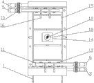
Accompanying drawing 1 is a kind of structural representation of the present utility model;
Accompanying drawing 2 is backsight structural representations of Fig. 1;
Accompanying drawing 3 is left TV structure schematic diagram of Fig. 1;
Accompanying drawing 4 is right TV structure schematic diagram of Fig. 1.
Component, position and numbering in figure: support 1, membrane stack 2, electrodialysis fresh water fluid inlet 3, electrodialysis fresh water liquid outlet 4, the dense water fluid inlet 5 of electrodialysis, the dense water liquid outlet 6 of electrodialysis, electrodialysis utmost point water fluid inlet 7, circulation line 8, electrodialysis utmost point water liquid outlet 9, union 10, water distributing pipe 11, positive terminal 12, negative terminal 13, electrode connection box 14, stiffening web 15, water distributing pipe support 16, water distribution pipeline perforate 17, electrode terminal perforate 18.
Embodiment
Below by embodiment, and by reference to the accompanying drawings, the technical solution of the utility model is described in further detail.
Embodiment: the electrodialysis unit of this routine pressure strip back design electrode connection box, as Fig. 1, Fig. 2, Fig. 3, Fig. 4, comprise support 1, support is provided with respectively by the light chamber of pipeline connection, utmost point chamber, the membrane stack 2 of dense chamber, membrane stack place is provided with electrodialysis fresh water fluid inlet 3, electrodialysis fresh water liquid outlet 4, the dense water fluid inlet 5 of electrodialysis, the dense water liquid outlet 6 of electrodialysis, utmost point chamber is connected with electrodialysis utmost point water fluid inlet 7, electrodialysis utmost point water fluid inlet connects electrodialysis utmost point water liquid outlet 9 by circulation line 8, the both sides of described membrane stack are respectively equipped with battery lead plate, the back side of battery lead plate is provided with positive terminal 12, negative terminal 13.The back side of battery lead plate is provided with water distributing pipe 11, between the water distributing pipe of membrane stack, all by union 10, connects.The outside of battery lead plate is provided with pressure strip, and pressure strip back is provided with electrode connection box 14.Pressure strip is provided with stiffening web 15.Pressure strip is provided with water distributing pipe support 16, and water distributing pipe 11 is arranged on water distributing pipe support.Pressure strip is with water distributing pipe perforate 17, electrode terminal perforate 18.
During use, by electrodialysis utmost point water fluid inlet 7, the utmost point water of utmost point chamber is incorporated in utmost point water circulation pipe 8, is communicated with positive terminal 12, negative terminal 13 conductions, finally from electrodialysis utmost point water liquid outlet 9, get back to extremely indoor.The light indoor material (as sodium chloride solution) that contains electrolyte solution that adds, the dense indoor pure water that adds, imports light, dense indoor material and pure water in membrane stack by water pump.Membrane stack is comprised of out-phase anion and cation exchange membrane, anion-exchange membrane is separated by the dividing plate containing different runners from cationic exchange membrane is middle, in logical galvanic situation, yin, yang ion displacement in material is added the selection perviousness (anion-exchange membrane can only can only pass through positively charged ion by negatively charged ion, cationic exchange membrane) of ion-exchange membrane, thereby makes light indoor electrolyte to dense chamber.
The foregoing is only specific embodiment of the utility model, but constitutional features of the present utility model is not limited to this, any those skilled in the art is in field of the present utility model, and the variation of doing or modification are all encompassed among the scope of the claims of the present utility model.
Claims (7)
1. the electrodialysis unit of pressure strip back design electrode connection box, comprise support (1), it is characterized in that described support is provided with respectively by the light chamber of pipeline connection, utmost point chamber, the membrane stack of dense chamber (2), membrane stack place is provided with electrodialysis fresh water fluid inlet (3), electrodialysis fresh water liquid outlet (4), the dense water fluid inlet of electrodialysis (5), the dense water liquid outlet of electrodialysis (6), utmost point chamber is connected with electrodialysis utmost point water fluid inlet (7), electrodialysis utmost point water fluid inlet connects electrodialysis utmost point water liquid outlet (9) by circulation line (8), the both sides of membrane stack are respectively equipped with pressure strip, the back of pressure strip is provided with electrode connection box (14).
2. the electrodialysis unit of electrode connection box is designed at pressure strip according to claim 1 back, in the pressure strip of membrane stack (2) both sides described in it is characterized in that, be provided with battery lead plate, the back side of battery lead plate is provided with positive terminal (12), negative terminal (13).
3. the electrodialysis unit of pressure strip according to claim 2 back design electrode connection box, is characterized in that the back side of described battery lead plate is provided with water distributing pipe (11), between the water distributing pipe of membrane stack, all by union (10), connects.
4. the electrodialysis unit of pressure strip according to claim 1 and 2 back design electrode connection box, is characterized in that described pressure strip is provided with stiffening web (15).
5. the electrodialysis unit of pressure strip according to claim 3 back design electrode connection box, is characterized in that described pressure strip is provided with water distributing pipe support (16), and water distributing pipe (11) is arranged on water distributing pipe support.
6. the electrodialysis unit of pressure strip according to claim 1 and 2 back design electrode connection box, is characterized in that described pressure strip is with water distributing pipe perforate (17).
7. the electrodialysis unit of pressure strip according to claim 1 and 2 back design electrode connection box, is characterized in that described pressure strip is with electrode terminal perforate (18).
Priority Applications (1)
| Application Number | Priority Date | Filing Date | Title |
|---|---|---|---|
| CN201320514532.8U CN203411374U (en) | 2013-08-22 | 2013-08-22 | Electrodialysis device with electrode junction boxes on backs of compaction plates |
Applications Claiming Priority (1)
| Application Number | Priority Date | Filing Date | Title |
|---|---|---|---|
| CN201320514532.8U CN203411374U (en) | 2013-08-22 | 2013-08-22 | Electrodialysis device with electrode junction boxes on backs of compaction plates |
Publications (1)
| Publication Number | Publication Date |
|---|---|
| CN203411374U true CN203411374U (en) | 2014-01-29 |
Family
ID=49974278
Family Applications (1)
| Application Number | Title | Priority Date | Filing Date |
|---|---|---|---|
| CN201320514532.8U Expired - Lifetime CN203411374U (en) | 2013-08-22 | 2013-08-22 | Electrodialysis device with electrode junction boxes on backs of compaction plates |
Country Status (1)
| Country | Link |
|---|---|
| CN (1) | CN203411374U (en) |
Cited By (2)
| Publication number | Priority date | Publication date | Assignee | Title |
|---|---|---|---|---|
| CN104841280A (en) * | 2015-05-15 | 2015-08-19 | 浙江沐源环境工程有限公司 | Electrode plate back-wiring quick-to-mount terminal for electrodialysis device |
| CN105110429A (en) * | 2015-07-27 | 2015-12-02 | 杭州埃尔环保科技有限公司 | Membrane medium ion generator designed for bidirectional electrode plate |
-
2013
- 2013-08-22 CN CN201320514532.8U patent/CN203411374U/en not_active Expired - Lifetime
Cited By (2)
| Publication number | Priority date | Publication date | Assignee | Title |
|---|---|---|---|---|
| CN104841280A (en) * | 2015-05-15 | 2015-08-19 | 浙江沐源环境工程有限公司 | Electrode plate back-wiring quick-to-mount terminal for electrodialysis device |
| CN105110429A (en) * | 2015-07-27 | 2015-12-02 | 杭州埃尔环保科技有限公司 | Membrane medium ion generator designed for bidirectional electrode plate |
Similar Documents
| Publication | Publication Date | Title |
|---|---|---|
| CN109755604B (en) | Neutral zinc-iodine flow battery | |
| CN203411374U (en) | Electrodialysis device with electrode junction boxes on backs of compaction plates | |
| CN203458985U (en) | Electrodialysis device for pressing plate with design of reinforcing ribs | |
| CN101562257B (en) | All vanadium redox flow battery structure | |
| CN203411373U (en) | Electro-osmosis device in frame-reinforced type compression plate design | |
| CN203967209U (en) | The capacity of a kind of 12V is 100Ah and following horizontal lead acid accumulator | |
| CN203411375U (en) | Electrodialysis device with water distribution pipe bracket design on compaction plates | |
| CN204973607U (en) | Detachable electrodialysis device of electrode integrated design | |
| CN203411376U (en) | Electrodialysis device provided with water distribution pipelines on back of plate electrodes | |
| CN204544005U (en) | The electrodialysis plant of membrane stack band positioning and guiding bar | |
| CN203458984U (en) | Electrodialysis plant with electrode binding posts on plate electrode backs | |
| CN205011440U (en) | Detachable electrodialysis device of back wiring type plate electrode | |
| CN205419872U (en) | Novel cylindrical electrodialysis of disk type device | |
| CN203355620U (en) | Novel electrodialysis membrane combined equipment | |
| CN202478824U (en) | Electroosmosis experimental device with electrolysis electrode chambers in series | |
| CN206858232U (en) | A kind of EDI devices | |
| CN200999211Y (en) | Electrodialysis set for concentration salt-production | |
| CN205077154U (en) | Electrolytic device of preparation high concentration vanadium electrolyte | |
| CN204873965U (en) | Detachable electrodialysis device of back wiring type plate electrode | |
| CN202427361U (en) | Movable electrodialysis experimental device | |
| CN202446985U (en) | Electroosmosis experiment device with emptying valve | |
| CN202434639U (en) | Flow battery for off-grid wind and light complementary power supply system | |
| CN105585083A (en) | Novel disk-type cylindrical electrodialysis plant | |
| CN204873966U (en) | Membrane medium ion generator of two -way plate electrode design | |
| CN113964359A (en) | Energy storage system and energy storage method for organic flow battery and all-vanadium flow battery in complementation mode |
Legal Events
| Date | Code | Title | Description |
|---|---|---|---|
| C14 | Grant of patent or utility model | ||
| GR01 | Patent grant | ||
| CX01 | Expiry of patent term | ||
| CX01 | Expiry of patent term |
Granted publication date: 20140129 |