CN203386921U - Novel wire connector - Google Patents
Novel wire connector Download PDFInfo
- Publication number
- CN203386921U CN203386921U CN201320261553.3U CN201320261553U CN203386921U CN 203386921 U CN203386921 U CN 203386921U CN 201320261553 U CN201320261553 U CN 201320261553U CN 203386921 U CN203386921 U CN 203386921U
- Authority
- CN
- China
- Prior art keywords
- copper pipe
- copper
- arc
- tee
- sheets
- Prior art date
- Legal status (The legal status is an assumption and is not a legal conclusion. Google has not performed a legal analysis and makes no representation as to the accuracy of the status listed.)
- Expired - Fee Related
Links
Images
Landscapes
- Cable Accessories (AREA)
Abstract
The utility model aims to mainly solve the problem that a conventional conducting wire is poor in mechanical property at the connection position, is easy to age and heat, etc. The technical scheme used to solve the technical problem of the utility model is that a novel wire connector is mainly composed of a copper pipe and an insulating nut, the two ends of the copper pipe are respectively equipped with tee arc-shaped copper sheet structures each of which the interior is equipped with annular concave-convex grooves, and the exterior is equipped with screws, and an insulating plastic is wrapped on the outer layer of the middle part of the copper pipe; each tee arc-shaped copper sheet is thinned gradually from the middle to the two ends, is narrowed gradually, and is an inverted trapezoidal shape; the insulating nut is sleeved on the tee arc-shaped copper sheets of the copper pipe and is rotated from the outer end to the middle, so that the tee arc-shaped copper sheets are extruded towards the center, and an opening is shrunk to clamp a conducting wire inserted in the opening. The copper sheets are equipped with transverse concave/convex grooves, on the condition that the contact area is large enough, the friction is increased, and the mechanical strength of stretching resistance is improved. A naked copper wire is wrapped by the plastic insulating nut effectively, so that the safety is increased.
Description
Technical field
The utility model is related to a kind of conductor jointer.
Background technology
Line ball method, welding and twisted wire method are used the method that wire is connected in daily life more.Line ball method firm and reliable connection, contact resistance is small.Having the disadvantage must be impracticable in family and daily life using professional hydraulic pressure Press Plier.Welding firm and reliable connection, contact resistance is small.Have the disadvantage to need professional tool flatiron, be not that the electrician personnel of specialty are difficult to realize, and inconvenient operation needs insulating tape to wind, there is problem of aging after welding, can be leaked electricity using long.Twisted wire method is most universal, simple to operate, easy to use.Have the disadvantage that mechanical performance is poor.This connection, is not the connection of cross section, is more the contact on surface, so contact area is more much smaller than wire stage casing, resistance is naturally big.Time is slightly long, and junction contact resistance can increase, generate heat, and causes circuit switch-on and -off, and voltage is fluctuated, or even causes fire.It fact proved that the generation of many electrical fires is exactly that this connection method is caused.The particularly connection of single condctor and multicore cable or multicore cable and multicore cable, such case is easier to occur.This connection method, needs also exist for insulating tape winding, there are problems that tracking.
The plug-in type conductor jointer that uses on the market at present, using shell fragment connection more than principle, mechanical strength is weak, it is impossible to bear larger pulling force.Because contact resistance is big, be not suitable for the connection of high-power electric appliance.
Utility model content
The technical problem that the utility model is solved is to provide a kind of new-type conductor jointer for solving the problems such as connecting position of wires bad mechanical property, easy aging and contact surface too small easy heating.
The technical solution of the utility model is:A kind of new-type conductor jointer, the new-type conductor jointer is mainly made up of copper pipe and insulating nut, and the two ends of copper pipe are made up of three bifurcated arc copper sheets of the annular tongue and groove of interior band, tyre screw, and three bifurcated arc copper sheets are thinning by thickness from the middle to both ends, narrow from the width, ambroin is wrapped up in outside copper pipe;Insulating nut is enclosed within three bifurcated arc copper sheets of copper pipe and can rotated from copper pipe outer end to centre.
The beneficial effects of the utility model are that high mechanical strength, contact resistance are small, outward appearance is exquisite, long lifespan, ageing-resistant, high pressure resistant high temperature, safe and reliable;Install, test, overhauling convenient;It is adapted to the electrical connection, terminal box inside conductor conversion connection and household electrical appliance electrical connection of all kinds of light fixtures;Have the advantages that easy to operate, safe and have a wide range of application.
Brief description of the drawings
The utility model is further illustrated with reference to the accompanying drawings and examples.
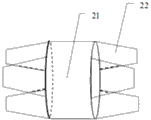
Fig. 1 is the structural representation of the utility model embodiment copper pipe.
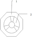
Fig. 2 is the sectional view that the utility model embodiment is fixed after wire.
Embodiment
In Fig. 1, the shape of three bifurcated arc copper sheets 22 is processed at the two ends of copper pipe 2, and middle part outer layer is wrapped with ambroin 21.The annular tongue and groove of band, outer threaded in the outer end of three bifurcated arc copper sheets 22, thinning by thickness from centre to outer end, narrows from the width, in the shape of inverted trapezoidal.
In fig. 2, insulating nut 1 be enclosed within three bifurcated arc copper sheets 22 of tyre screw from outer end to centre rotate when, three bifurcated arc copper sheets 22 are extruded to center, and opening diminishes, and clamps the wire of insertion opening.There is horizontal tongue and groove on three bifurcated arc copper sheets 22, in the case where contact area is sufficiently large, increase friction improves the mechanical strength of stretching resistance, using insulating nut 1, effectively wrapped up exposed copper sheet, increases security.
Claims (1)
1. a kind of new-type conductor jointer, the new-type conductor jointer is mainly made up of copper pipe and insulating nut, it is characterised in that:The two ends of copper pipe are made up of three bifurcated arc copper sheets of the annular tongue and groove of interior band, tyre screw, and three bifurcated arc copper sheets are thinning by thickness from the middle to both ends, narrow from the width, ambroin is wrapped up in outside copper pipe;Insulating nut is enclosed within three bifurcated arc copper sheets of copper pipe and can rotated from copper pipe outer end to centre.
Priority Applications (1)
| Application Number | Priority Date | Filing Date | Title |
|---|---|---|---|
| CN201320261553.3U CN203386921U (en) | 2013-05-14 | 2013-05-14 | Novel wire connector |
Applications Claiming Priority (1)
| Application Number | Priority Date | Filing Date | Title |
|---|---|---|---|
| CN201320261553.3U CN203386921U (en) | 2013-05-14 | 2013-05-14 | Novel wire connector |
Publications (1)
| Publication Number | Publication Date |
|---|---|
| CN203386921U true CN203386921U (en) | 2014-01-08 |
Family
ID=49875375
Family Applications (1)
| Application Number | Title | Priority Date | Filing Date |
|---|---|---|---|
| CN201320261553.3U Expired - Fee Related CN203386921U (en) | 2013-05-14 | 2013-05-14 | Novel wire connector |
Country Status (1)
| Country | Link |
|---|---|
| CN (1) | CN203386921U (en) |
Cited By (2)
| Publication number | Priority date | Publication date | Assignee | Title |
|---|---|---|---|---|
| CN104682030A (en) * | 2015-02-07 | 2015-06-03 | 国家电网公司 | Line cleat of distribution line |
| CN108039592A (en) * | 2017-12-23 | 2018-05-15 | 河南智金网络技术有限公司 | A kind of soft silk thread quick connector of multiply |
-
2013
- 2013-05-14 CN CN201320261553.3U patent/CN203386921U/en not_active Expired - Fee Related
Cited By (2)
| Publication number | Priority date | Publication date | Assignee | Title |
|---|---|---|---|---|
| CN104682030A (en) * | 2015-02-07 | 2015-06-03 | 国家电网公司 | Line cleat of distribution line |
| CN108039592A (en) * | 2017-12-23 | 2018-05-15 | 河南智金网络技术有限公司 | A kind of soft silk thread quick connector of multiply |
Similar Documents
| Publication | Publication Date | Title |
|---|---|---|
| CN203386921U (en) | Novel wire connector | |
| CN204330841U (en) | A kind of electric energy meter terminating wire locking device | |
| CN206301979U (en) | High-voltage connector | |
| CN203242774U (en) | Wiring terminal | |
| CN204407535U (en) | One exempts from wire stripping deconcentrator | |
| CN204905802U (en) | Cable connection structure that can set up in open | |
| CN202872005U (en) | Energy-saving electrical connector | |
| CN203896300U (en) | Locking force-strengthened photovoltaic connector | |
| CN205790534U (en) | A kind of socket clamping conductor | |
| CN104993434A (en) | Cable connecting structure | |
| CN109818205B (en) | Electrical connector for contacting electrical components | |
| CN204333505U (en) | Safety energy-saving electric transmission terminal | |
| CN202444062U (en) | Fixing device for inserted electric connection of multi-core leads | |
| CN211062888U (en) | Can prevent cracked automatic professional termination of wire connection department | |
| CN203590483U (en) | Connecting terminal mechanism of electric blanket | |
| CN218770446U (en) | Three-hole plug with temperature control function | |
| CN203135028U (en) | Power supply plugboard | |
| CN204243266U (en) | A kind of high current connector | |
| CN204885474U (en) | Take screw hold -down mechanism's electric wire connector | |
| CN202749524U (en) | Lead wire connecting board inside wall | |
| CN204464560U (en) | A kind of hexagon cable connector | |
| CN201369396Y (en) | Connecting body used for connecting electric wires | |
| CN203056114U (en) | Cable connecting device | |
| CN105846130A (en) | Power transmission and distribution puncture wire clamp | |
| CN203644993U (en) | Power plug |
Legal Events
| Date | Code | Title | Description |
|---|---|---|---|
| C14 | Grant of patent or utility model | ||
| GR01 | Patent grant | ||
| C17 | Cessation of patent right | ||
| CF01 | Termination of patent right due to non-payment of annual fee |
Granted publication date: 20140108 Termination date: 20140514 |