CN203384410U - Slit valve for limiting passage of flowing matter between internal environment and external environment - Google Patents
Slit valve for limiting passage of flowing matter between internal environment and external environment Download PDFInfo
- Publication number
- CN203384410U CN203384410U CN201320118250.6U CN201320118250U CN203384410U CN 203384410 U CN203384410 U CN 203384410U CN 201320118250 U CN201320118250 U CN 201320118250U CN 203384410 U CN203384410 U CN 203384410U
- Authority
- CN
- China
- Prior art keywords
- valve
- head
- slit valve
- attachment part
- slit
- Prior art date
- Legal status (The legal status is an assumption and is not a legal conclusion. Google has not performed a legal analysis and makes no representation as to the accuracy of the status listed.)
- Expired - Lifetime
Links
- 239000000463 material Substances 0.000 claims abstract description 82
- 239000012528 membrane Substances 0.000 claims abstract description 15
- 230000002093 peripheral effect Effects 0.000 claims description 18
- 230000008859 change Effects 0.000 claims description 2
- 238000000034 method Methods 0.000 abstract description 16
- 238000012856 packing Methods 0.000 description 20
- 230000009467 reduction Effects 0.000 description 16
- 239000012530 fluid Substances 0.000 description 14
- 238000003856 thermoforming Methods 0.000 description 10
- 230000003321 amplification Effects 0.000 description 6
- 229920001684 low density polyethylene Polymers 0.000 description 6
- 239000004702 low-density polyethylene Substances 0.000 description 6
- 238000003199 nucleic acid amplification method Methods 0.000 description 6
- 238000007493 shaping process Methods 0.000 description 6
- 239000002775 capsule Substances 0.000 description 5
- 230000008569 process Effects 0.000 description 5
- MEYZYGMYMLNUHJ-UHFFFAOYSA-N tunicamycin Natural products CC(C)CCCCCCCCCC=CC(=O)NC1C(O)C(O)C(CC(O)C2OC(C(O)C2O)N3C=CC(=O)NC3=O)OC1OC4OC(CO)C(O)C(O)C4NC(=O)C MEYZYGMYMLNUHJ-UHFFFAOYSA-N 0.000 description 5
- 238000010586 diagram Methods 0.000 description 4
- 229920000092 linear low density polyethylene Polymers 0.000 description 4
- 239000004707 linear low-density polyethylene Substances 0.000 description 4
- 238000007789 sealing Methods 0.000 description 4
- 239000005038 ethylene vinyl acetate Substances 0.000 description 3
- 229920003023 plastic Polymers 0.000 description 3
- 239000004033 plastic Substances 0.000 description 3
- QQONPFPTGQHPMA-UHFFFAOYSA-N Propene Chemical compound CC=C QQONPFPTGQHPMA-UHFFFAOYSA-N 0.000 description 2
- 239000004699 Ultra-high molecular weight polyethylene Substances 0.000 description 2
- 239000012080 ambient air Substances 0.000 description 2
- 230000008901 benefit Effects 0.000 description 2
- 230000015572 biosynthetic process Effects 0.000 description 2
- 238000000071 blow moulding Methods 0.000 description 2
- DQXBYHZEEUGOBF-UHFFFAOYSA-N but-3-enoic acid;ethene Chemical compound C=C.OC(=O)CC=C DQXBYHZEEUGOBF-UHFFFAOYSA-N 0.000 description 2
- 239000003795 chemical substances by application Substances 0.000 description 2
- 238000010276 construction Methods 0.000 description 2
- 238000013461 design Methods 0.000 description 2
- 235000013399 edible fruits Nutrition 0.000 description 2
- 238000005516 engineering process Methods 0.000 description 2
- 238000001125 extrusion Methods 0.000 description 2
- 229920001903 high density polyethylene Polymers 0.000 description 2
- 239000004700 high-density polyethylene Substances 0.000 description 2
- 238000009434 installation Methods 0.000 description 2
- 238000004093 laser heating Methods 0.000 description 2
- 238000012423 maintenance Methods 0.000 description 2
- 239000000203 mixture Substances 0.000 description 2
- 230000004048 modification Effects 0.000 description 2
- 238000012986 modification Methods 0.000 description 2
- 238000000465 moulding Methods 0.000 description 2
- 229920001200 poly(ethylene-vinyl acetate) Polymers 0.000 description 2
- 229920000642 polymer Polymers 0.000 description 2
- 238000007639 printing Methods 0.000 description 2
- 230000005855 radiation Effects 0.000 description 2
- 230000003068 static effect Effects 0.000 description 2
- 229920001169 thermoplastic Polymers 0.000 description 2
- 229920002725 thermoplastic elastomer Polymers 0.000 description 2
- 229920001187 thermosetting polymer Polymers 0.000 description 2
- 229920000785 ultra high molecular weight polyethylene Polymers 0.000 description 2
- 238000007666 vacuum forming Methods 0.000 description 2
- VGGSQFUCUMXWEO-UHFFFAOYSA-N Ethene Chemical compound C=C VGGSQFUCUMXWEO-UHFFFAOYSA-N 0.000 description 1
- JOYRKODLDBILNP-UHFFFAOYSA-N Ethyl urethane Chemical compound CCOC(N)=O JOYRKODLDBILNP-UHFFFAOYSA-N 0.000 description 1
- 239000004743 Polypropylene Substances 0.000 description 1
- PPBRXRYQALVLMV-UHFFFAOYSA-N Styrene Chemical compound C=CC1=CC=CC=C1 PPBRXRYQALVLMV-UHFFFAOYSA-N 0.000 description 1
- DHKHKXVYLBGOIT-UHFFFAOYSA-N acetaldehyde Diethyl Acetal Natural products CCOC(C)OCC DHKHKXVYLBGOIT-UHFFFAOYSA-N 0.000 description 1
- 125000002777 acetyl group Chemical class [H]C([H])([H])C(*)=O 0.000 description 1
- 229920002301 cellulose acetate Polymers 0.000 description 1
- 230000000694 effects Effects 0.000 description 1
- 239000013013 elastic material Substances 0.000 description 1
- 239000011521 glass Substances 0.000 description 1
- 230000026030 halogenation Effects 0.000 description 1
- 238000005658 halogenation reaction Methods 0.000 description 1
- 239000007788 liquid Substances 0.000 description 1
- 229920000728 polyester Polymers 0.000 description 1
- -1 polypropylene Polymers 0.000 description 1
- 229920001155 polypropylene Polymers 0.000 description 1
- 229920001296 polysiloxane Polymers 0.000 description 1
- 238000007634 remodeling Methods 0.000 description 1
- 230000004044 response Effects 0.000 description 1
- 229920002379 silicone rubber Polymers 0.000 description 1
- 239000004945 silicone rubber Substances 0.000 description 1
- 239000000126 substance Substances 0.000 description 1
- 239000004634 thermosetting polymer Substances 0.000 description 1
- 239000004416 thermosoftening plastic Substances 0.000 description 1
Images


Classifications
-
- F—MECHANICAL ENGINEERING; LIGHTING; HEATING; WEAPONS; BLASTING
- F16—ENGINEERING ELEMENTS AND UNITS; GENERAL MEASURES FOR PRODUCING AND MAINTAINING EFFECTIVE FUNCTIONING OF MACHINES OR INSTALLATIONS; THERMAL INSULATION IN GENERAL
- F16K—VALVES; TAPS; COCKS; ACTUATING-FLOATS; DEVICES FOR VENTING OR AERATING
- F16K15/00—Check valves
- F16K15/14—Check valves with flexible valve members
-
- B—PERFORMING OPERATIONS; TRANSPORTING
- B65—CONVEYING; PACKING; STORING; HANDLING THIN OR FILAMENTARY MATERIAL
- B65D—CONTAINERS FOR STORAGE OR TRANSPORT OF ARTICLES OR MATERIALS, e.g. BAGS, BARRELS, BOTTLES, BOXES, CANS, CARTONS, CRATES, DRUMS, JARS, TANKS, HOPPERS, FORWARDING CONTAINERS; ACCESSORIES, CLOSURES, OR FITTINGS THEREFOR; PACKAGING ELEMENTS; PACKAGES
- B65D47/00—Closures with filling and discharging, or with discharging, devices
- B65D47/04—Closures with discharging devices other than pumps
-
- B—PERFORMING OPERATIONS; TRANSPORTING
- B29—WORKING OF PLASTICS; WORKING OF SUBSTANCES IN A PLASTIC STATE IN GENERAL
- B29C—SHAPING OR JOINING OF PLASTICS; SHAPING OF MATERIAL IN A PLASTIC STATE, NOT OTHERWISE PROVIDED FOR; AFTER-TREATMENT OF THE SHAPED PRODUCTS, e.g. REPAIRING
- B29C51/00—Shaping by thermoforming, i.e. shaping sheets or sheet like preforms after heating, e.g. shaping sheets in matched moulds or by deep-drawing; Apparatus therefor
-
- B—PERFORMING OPERATIONS; TRANSPORTING
- B65—CONVEYING; PACKING; STORING; HANDLING THIN OR FILAMENTARY MATERIAL
- B65D—CONTAINERS FOR STORAGE OR TRANSPORT OF ARTICLES OR MATERIALS, e.g. BAGS, BARRELS, BOTTLES, BOXES, CANS, CARTONS, CRATES, DRUMS, JARS, TANKS, HOPPERS, FORWARDING CONTAINERS; ACCESSORIES, CLOSURES, OR FITTINGS THEREFOR; PACKAGING ELEMENTS; PACKAGES
- B65D35/00—Pliable tubular containers adapted to be permanently or temporarily deformed to expel contents, e.g. collapsible tubes for toothpaste or other plastic or semi-liquid material; Holders therefor
- B65D35/44—Closures
- B65D35/46—Closures with valves
-
- B—PERFORMING OPERATIONS; TRANSPORTING
- B65—CONVEYING; PACKING; STORING; HANDLING THIN OR FILAMENTARY MATERIAL
- B65D—CONTAINERS FOR STORAGE OR TRANSPORT OF ARTICLES OR MATERIALS, e.g. BAGS, BARRELS, BOTTLES, BOXES, CANS, CARTONS, CRATES, DRUMS, JARS, TANKS, HOPPERS, FORWARDING CONTAINERS; ACCESSORIES, CLOSURES, OR FITTINGS THEREFOR; PACKAGING ELEMENTS; PACKAGES
- B65D47/00—Closures with filling and discharging, or with discharging, devices
- B65D47/04—Closures with discharging devices other than pumps
- B65D47/20—Closures with discharging devices other than pumps comprising hand-operated members for controlling discharge
- B65D47/2018—Closures with discharging devices other than pumps comprising hand-operated members for controlling discharge comprising a valve or like element which is opened or closed by deformation of the container or closure
- B65D47/2031—Closures with discharging devices other than pumps comprising hand-operated members for controlling discharge comprising a valve or like element which is opened or closed by deformation of the container or closure the element being formed by a slit, narrow opening or constrictable spout, the size of the outlet passage being able to be varied by increasing or decreasing the pressure
-
- B—PERFORMING OPERATIONS; TRANSPORTING
- B65—CONVEYING; PACKING; STORING; HANDLING THIN OR FILAMENTARY MATERIAL
- B65D—CONTAINERS FOR STORAGE OR TRANSPORT OF ARTICLES OR MATERIALS, e.g. BAGS, BARRELS, BOTTLES, BOXES, CANS, CARTONS, CRATES, DRUMS, JARS, TANKS, HOPPERS, FORWARDING CONTAINERS; ACCESSORIES, CLOSURES, OR FITTINGS THEREFOR; PACKAGING ELEMENTS; PACKAGES
- B65D75/00—Packages comprising articles or materials partially or wholly enclosed in strips, sheets, blanks, tubes or webs of flexible sheet material, e.g. in folded wrappers
- B65D75/52—Details
- B65D75/58—Opening or contents-removing devices added or incorporated during package manufacture
- B65D75/5861—Spouts
- B65D75/5872—Non-integral spouts
- B65D75/5883—Non-integral spouts connected to the package at the sealed junction of two package walls
-
- F—MECHANICAL ENGINEERING; LIGHTING; HEATING; WEAPONS; BLASTING
- F16—ENGINEERING ELEMENTS AND UNITS; GENERAL MEASURES FOR PRODUCING AND MAINTAINING EFFECTIVE FUNCTIONING OF MACHINES OR INSTALLATIONS; THERMAL INSULATION IN GENERAL
- F16K—VALVES; TAPS; COCKS; ACTUATING-FLOATS; DEVICES FOR VENTING OR AERATING
- F16K15/00—Check valves
- F16K15/14—Check valves with flexible valve members
- F16K15/144—Check valves with flexible valve members the closure elements being fixed along all or a part of their periphery
- F16K15/147—Check valves with flexible valve members the closure elements being fixed along all or a part of their periphery the closure elements having specially formed slits or being of an elongated easily collapsible form
-
- F—MECHANICAL ENGINEERING; LIGHTING; HEATING; WEAPONS; BLASTING
- F16—ENGINEERING ELEMENTS AND UNITS; GENERAL MEASURES FOR PRODUCING AND MAINTAINING EFFECTIVE FUNCTIONING OF MACHINES OR INSTALLATIONS; THERMAL INSULATION IN GENERAL
- F16K—VALVES; TAPS; COCKS; ACTUATING-FLOATS; DEVICES FOR VENTING OR AERATING
- F16K21/00—Fluid-delivery valves, e.g. self-closing valves
- F16K21/04—Self-closing valves, i.e. closing automatically after operation
-
- Y—GENERAL TAGGING OF NEW TECHNOLOGICAL DEVELOPMENTS; GENERAL TAGGING OF CROSS-SECTIONAL TECHNOLOGIES SPANNING OVER SEVERAL SECTIONS OF THE IPC; TECHNICAL SUBJECTS COVERED BY FORMER USPC CROSS-REFERENCE ART COLLECTIONS [XRACs] AND DIGESTS
- Y10—TECHNICAL SUBJECTS COVERED BY FORMER USPC
- Y10T—TECHNICAL SUBJECTS COVERED BY FORMER US CLASSIFICATION
- Y10T29/00—Metal working
- Y10T29/49—Method of mechanical manufacture
- Y10T29/49405—Valve or choke making
Landscapes
- Engineering & Computer Science (AREA)
- Mechanical Engineering (AREA)
- General Engineering & Computer Science (AREA)
- Closures For Containers (AREA)
- Check Valves (AREA)
- Lift Valve (AREA)
- Containers And Packaging Bodies Having A Special Means To Remove Contents (AREA)
- Medicinal Preparation (AREA)
- Medical Preparation Storing Or Oral Administration Devices (AREA)
- Packages (AREA)
- Coating Apparatus (AREA)
- Bag Frames (AREA)
- Particle Formation And Scattering Control In Inkjet Printers (AREA)
- Chemical Vapour Deposition (AREA)
Abstract
The utility model relates to a slit valve (10) for selectively limiting the passage of a flowing matter between an internal environment (17) and an external environment (15) and a method for forming the valve (10). The method comprises the following steps: providing at least one layer of a membrane material; enabling the membrane material to be permanently deformed and consequently limiting the valve (10) so as to selectively limit the passage of the flowing matter between the internal environment (17) and the external environment (15).
Description
Technical field
The utility model relates in general to for optionally controlling mobile valve and the system of stream material, relates more specifically to for optionally limiting the mobile valve of stream material between internal environment and external environment condition-for example, for the valve from container or other source dispensed product.
Background technique
The flexibility of one type, elastic valve are to be installed to self-closing, the slit-type valve on the port in other sources of stream material container or stream material by accessory.This valve has the slit of the normally closed small opening of one or more restrictions, described slit in response to the pressure reduction of the increase of valve (for example, the pressure increased in container during by squeeze receptacle causes, or is caused by the external environment condition pressure that the pressure with in container is compared reduction) thus and open and allow flow of matter by described slit.This valve is usually designed to and makes their auto-closings when the pressure reduction of valve reduces cut off flowing wherein.
This valve and use the design of the accessory of this valve to be set forth in U.S. Patent No. 5271732, No.5927446, No.5942712 and No.6545901.Usually, described accessory is to comprise being arranged on container neck the body that limits seat or the form of the closure member of base portion, and described seat is for holding described valve, and this closure member comprises retaining ring or other structures on the seat for described valve being remained on to described base portion.For example, referring to U.S. Patent No. 6269986 and No.6566016.Described valve is weight normally closed and can bear fluid product when container reverses fully, so unless squeeze receptacle, liquid will can not leak out.By this system, that lid or cover do not need again is closed (although if packing to be transported to another location, be filled in suitcase when medium described lid or cover usually again closed).
Although this valve and valve system have remarkable advantage and fine use, always have improved space.
The model utility content
According to a feature of the present utility model, slit valve is arranged to optionally limit stream material passing through between internal environment and external environment condition.Described valve comprises flexible elastic force head, circular periphery attachment part and annular flexible elastic force intermediate portion.Described head is centered on central axis and from described central axis side extending, and there is the internal surface of face inside environment, in the face of the outer surface of external environment condition and without the permanent part opened of facing of closing small opening of restrained condition lower limit, the wherein said part of opening can move to small opening along first direction and opens structure and turn back in opposite direction closed structure.The internal surface of described head is in convex or concave surface, and the outer surface of described head is in convex surface or concave surface.Described attachment part is centered on central axis and with described lateral spacing and opens.Intermediate portion is centered on central axis and from described head and extends laterally to described peripheral attachment part.Described intermediate portion has the internal surface of facing described internal environment and the outer surface of facing external environment condition.The internal surface of described intermediate portion is in concave surface and convex surface, and the outer surface of described intermediate portion is one in concave surface and convex surface.Described head and described intermediate portion limit described head and described intermediate portion material membrane by standing permanent deformation forms.
According to a feature, the internal surface of described head and the outer surface of described intermediate portion are convex surface, and the outer surface of described head and the internal surface of described intermediate portion are concave surface.
As a feature, described head has through at least one selfsealings slit of described and the part opened of facing of extending along described at least one selfsealings slit.
In a feature, described homogeneous material thickness T is in the scope of 0.001 to 0.010 inch; In another feature, described homogeneous material thickness T is in the scope of 0.004 to 0.013 inch.
According to a feature, described attachment part has with flat outer surface with the isolated flat inner surface of homogeneous material thickness T.
In a feature, described attachment part has and the heterogeneous material thickness isolated internal surface of outer surface to change in the annular extent of described attachment part.As a further feature, the outer surface of described attachment part defines the cylindrical wall around described head and described intermediate portion.In another further feature, the internal surface of described attachment part and outer surface limit the annular flange flange extended radially outwardly.
As a feature, described head and described intermediate portion have described outer surface and the isolated homogeneous material thickness T of described internal surface, and wherein T is not more than 0.020 inch.
According to a feature, whole described valve is that the material membrane by permanent deformation limits.
In a feature, described valve and stream material container and the accessory combination that is installed to hermetically described container, described container has opening, by described opening stream material, can between the inside of described container and external environment condition, walk, be arranged in described accessory in order to extend and cross described opening wherein said valve seal, thereby at least when described restriction stream material passing through between the inside of described container and external environment condition while opening part in closed structure.
According to a feature of the present utility model, provide a kind of method that is used to form the current slit valve of the stream material between restricted internal environment and external environment condition optionally.Described method comprises the steps: to provide at least one tunic material, thereby and makes described membrane material for good and all be out of shape the valve that restriction has flexible elastic force head, circular periphery attachment part and annular flexible elastic force intermediate portion.Described head is centered on central axis and from described central axis side extending, and has the internal surface of face inside environment and in the face of the outer surface of external environment condition.The internal surface of described head is in convex surface or concave surface, and the outer surface of described head is in convex surface or concave surface.Described attachment part is centered on central axis and with described lateral spacing and opens.Described intermediate portion is centered on central axis and from described head and extends laterally to described peripheral attachment part, and has in the face of the internal surface of described internal environment and the outer surface of facing external environment condition.The internal surface of described intermediate portion is in concave surface and convex surface, and the outer surface of described intermediate portion is one in concave surface and convex surface.
As a feature, the step of described permanent deformation provides the homogeneous material thickness T to described head and intermediate portion, and wherein the homogeneous material thickness T is spaced apart by described outer surface and described internal surface, and wherein T is not more than 0.020 inch.
In a feature, the step of described permanent deformation further comprises described annular attachment part is defined as and has described homogeneous material thickness T.
According to a feature, described permanent deformation step further comprises described annular attachment part is defined as and has flat outer surface and flat inner surface.
In a feature, described homogeneous material thickness T is in the scope of 0.001 to 0.010 inch.
As a feature, thereby described method further is included in described head and forms at least one selfsealings slit and form the opened part faced along at least one slit in described head without the permanent step of closing small opening of restrained condition lower limit, the wherein said part of opening can move to small opening along first direction and opens and construct and turn back in opposite direction closed structure.
According to a feature, provide the step of at least one tunic material to comprise multi-layer film material is provided, and the permanent deformation step comprises and makes described a plurality of layers of permanent deformation and limit described valve.
As a feature, the step of permanent deformation comprises makes described at least one tunic thermoforming limit described valve.In further feature, hot formed step comprises by matched mold and is shaped to limit described valve.
In a feature, provide the step of described at least one tunic to comprise the injection-molded preformed member, at least one tunic that described preformed member has annular attachment part and extends radially inwardly from described annular attachment part.
By following, to detailed description of the present utility model, by claim and by accompanying drawing, many other advantages of the present utility model and feature will become apparent.
The accompanying drawing explanation
Accompanying drawing forms the part of specification, and wherein like reference numerals is used for indicating like at specification;
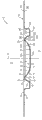
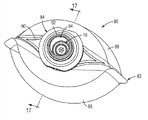
Fig. 1 is the amplification stereogram from adopting valve of the present utility model top to observe, and wherein said valve is depicted as in closed state;
Fig. 2 is the amplification stereogram from the beneath of the valve of Fig. 1, also shows the valve in closed state in figure;
Fig. 3 is the plan view of the valve of Fig. 1-2, and wherein said valve is also in closed state;
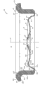
Fig. 4 is the sectional view that the line 4-4 from Fig. 3 observes;
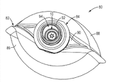
Fig. 5 is similar to Fig. 1 but shows the view in the valve of open mode;
Fig. 6 is similar to Fig. 2 but shows the view in the valve of open mode;
Fig. 7 is similar to Fig. 3 but shows the view in the valve of open mode;
Fig. 8 is similar to Fig. 4 but shows the view in the valve of open mode;
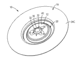
Fig. 9 is the stereogram of observing from fluid dispensing packing top, and wherein said fluid dispensing comprises the accessory of stream material container, closure member form and the valve of Fig. 1-8;
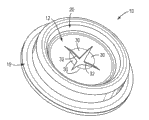
Figure 10 is the three-dimensional exploded view of observing from the packing top of Fig. 9;
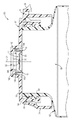
Figure 11 is the local amplification view that the line 11-11 from Fig. 9 observed and showed the valve in closed state;
Figure 12 is similar to Figure 11 but shows the view in the valve of open mode;
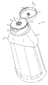
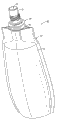
Figure 13 is the stereogram of observing from another fluid dispensing packing top, and wherein said another fluid dispensing comprises the valve of fluid material container, accessory and Fig. 1-12;
Figure 14 is another stereogram of the packing of Figure 13, there is shown the valve in closed state;
Figure 15 is similar to Figure 14 but shows the view in the valve of open mode;
Figure 16 is the three-dimensional exploded view of the packing of Figure 13-15;
Figure 17 is that the line 17-17 from Figure 14 observes and show the amplification view in the valve of closed state;
Figure 18 is the stereogram of observing from another mode of execution top according to valve of the present utility model, and wherein said valve is depicted as in closed state;
Figure 19 is the stereogram from the valve beneath of Figure 18, also shows the valve in closed state in figure;
Figure 20 is the plan view of the valve of Figure 18, and wherein said valve is also in closed state;
Figure 21 is the amplification view that the line 21-21 from Figure 20 observes;
Figure 22 is similar to Figure 18 but shows the view in the valve of open mode;
Figure 23 is similar to Figure 19 but shows the view in the valve of open mode;
Figure 24 is similar to Figure 20 but shows the view in the valve of open mode;
Figure 25 is similar to Figure 21 but shows the view in the valve of open mode;
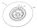
Figure 26 is the stereogram that is similar to the dispensing packing of dispensing packing in Fig. 9-12, but there is shown the valve of Figure 18-25;
Figure 27 is the three-dimensional exploded view of the dispensing packing of Figure 26;
Figure 28 is that the line 28-28 from Figure 26 observes and show the partial sectional view in the valve of closed state;
Figure 29 is similar to Figure 28 but shows the view in the valve of open mode;
Figure 30 is the stereogram of another dispensing packing that comprises the valve of Figure 18-29;
Figure 31 is another stereogram of the packing of Figure 30, and there is shown the valve in closed state;
Figure 32 is similar to Figure 31 but shows the view in the valve of open mode;
Figure 33 is the three-dimensional exploded view of the packing of Figure 30-32; And
Figure 34 is that the line 34-34 from Figure 31 observes and show the amplification view in the valve of closed state.
Embodiment
Although the utility model can have many multi-form mode of executions, specification and accompanying drawing only disclose a kind of particular form as example of the present utility model.Yet the utility model will be not limited to described mode of execution.List scope of the present utility model in claims.
For convenience of description, valve of the present utility model can be together with accessory be described in typical case (uprightly) position, and take the term that this position is benchmark use such as upper and lower, level etc.Yet, should be understood that, adopt valve of the present utility model can except above-mentioned position towards in manufactured, store, transport, use and sell.
The accompanying drawing that valve of the present utility model and related accessory are shown shows some conventional mechanical element known and that the those skilled in the art will recognize that.Understanding the utility model does not need the detailed description of these elements, and correspondingly, at this, only these elements is described to the convenient required degree of novel feature of the present utility model of understanding.
According to the current preferred implementation of valve of the present utility model, shown in Fig. 1-17 and generally, with number 10, indicating.In diagram and preferred embodiment, valve 10 comprises flexibility, elastic force middle body or 12, and described flexibility, elastic force middle body or 12 have first or outer surface 14 (illustrating at 15 places of Fig. 4 and 8 substantially) in the face of external environment condition and second or the internal surface 16 (illustrating at 17 places of Fig. 4 and 8 substantially) of face inside environment.Valve 10 further comprise peripheral attachment part or flange 19 and from the beginning 12 side direction extend outwardly into flexibility, the elastic force intermediate portion of flange 19 or overlap 20.After this, use term " cover " 20 in specification, but use in the claims term " intermediate portion " 20.
Valve 10 preferably by standing permanent deformation in case at least limit 12 and the material membrane of intermediate portion 20 form.About this point, material membrane can adopt suitable thermoforming operation for good and all to be out of shape, and described thermoforming operation comprises matched mold shaping, vacuum forming, core rod assist formation, vacuum resilience shaping, heat expansion shaping, free forming, pressure forming, covering moulding, online thermoforming (in-line thermal forming), the biplate material is shaped and the thermoforming (thin and thick gauge thermal forming) of thin and thick specification.Other suitable operations comprise cold type roller extrusion molding, cold forming, interior molded label technique, internal mold package technique, in die set, blow molding preformed member, rotogravure printing are shaped, rotation " cut and penetrate " (rotary " chip shot ") is molded, radio frequency (RF) is shaped, the local laser heating, described film is curled into to the etch process of valve shape and the valve UV (UV-b radiation) formed is solidified.A height preferable process for the valve 10 shown in Fig. 1-17, whole valve 10 is made by the LLDPE/LDPE mixture material film that in matched mold, forms permanent deformation in operation, wherein 12, overlap 20 and the shape shown of the inner radial of peripheral attachment part 19 permanent deformation by material membrane form, wherein the radially outer of peripheral attachment part 19 has the flat configuration identical with described membrane material.
As be clear that in Fig. 3 and 8,12 have flat, intersect, self-enclosed slit 28, and when valve 10, described slit 28 is common during in closed state limits closed small opening.Should be understood that, at initial, the closed state of the valve 10 shown in Fig. 1-4, the line of rabbet joint that each slit 28 is closed and does not have restriction to open.Preferably, slit 28 is spaced apart each other equidistantly and equal in length.In the graphic form of valve 10, slit 28 limits 6, fan-shaped, equal-sized baffle plate or fin 30 substantially in 12.Baffle plate or fin 30 also can have following characteristics, as " can open section " or " can open part " of valve head 12.Each baffle plate or fin 30 have limited by slit 28 a pair of and disperse landscape surface 32 (Fig. 8), and each landscape surface 32 seals the relative landscape surface 32 against adjacent fins 30 when valve 16 is closed.Have slit 28 although valve 10 can form, should be understood that, described slit 28 is cut into 12 of valve 10 by suitable routine techniques subsequently.As another alternative, at least one slit 28 can partly form to the end in 12, and the remainder of the slit 28 that wherein said at least one part forms is cut, cuts off, pierces through, tears, damages or otherwise separates after molded.About this point, should be understood that, as used herein, term " slit valve " will mean to have one or more slits when its final functional form-any valve of slit 28 for example, described any valve for example comprises, after slit 28 that wherein one or more slits-part forms is only in valve has formed and/or has been arranged on its operating environment the valve 10 of the slit 28 that at least one part of the valve that completed fully-for example have forms, the slit 28 that described at least one part forms has the frangible part in the accessory that is arranged on dispensing packing or machine, the frangible part of the slit 28 that wherein described during installation at least one part forms is excellent, and after installing, described at least one slit 28 is cut subsequently, cut off, pierce through, tear, complete described at least one slit 28 and described valve 10 is placed in to its final functional form thereby damage or otherwise separate.
Should be understood that, the small opening of valve 10 can limit by the structure outside illustrated straight slit 28.Further, slit 28 can have various difformities, size and/or the structure of the needs that meet each application-specific and parameter.For example, small opening only also can comprise a slit 28 or two or more crossed slots 28.
12, peripheral attachment part 19 and overlap 20 rotationally symmetric bodies of centering on central axis 27 preferably all.Preferably and as Figure 1-4, initial, without the constraint closed state, 12 outer surface 14 is spills, and 12 internal surface 16 is convexs, overlap 20 outer surface 24 is convexs, and overlap 20 internal surface 26, is spills.In addition, as be clear that in Fig. 4,12 outer surface 14 and internal surface 16 comprise respectively on the finite region of adjacency axis 27 flat 14A and the 16A from central axis 27 horizontal expansions.In addition, 12 outer surface 14 and internal surface 16 comprise respectively and extend into and overlap 20 arcuate section 14B and the 16B that are connected from flat 14A and 16A.In addition, outer surface 24 and the internal surface 26 of cover 20 comprise arcuate section 24A and 26A, described arcuate section 24A and 26A be 12 corresponding frusto-conically shaped portion 24B and 26B that extend radially outwardly into outer surface 24 and internal surface 26 from the beginning respectively, described frusto-conically shaped portion 24B and 26B then side direction extends outwardly into corresponding arcuate surfaces 24C and the 26C of outer surface 24 and internal surface 26.In addition, arcuate surfaces 24C stretches out into connection peripheral attachment part 19 with the 26C side direction.Should be understood that, 12 and cover 20 are the functional characters of valve 10 that affects characteristic of valve 10, wherein said attachment part 19 is only as structure valve 10 is installed in stream material control or delivery system.
In the embodiment shown and as be clear that in Fig. 4, peripheral attachment part 19 has outer surface 34 and internal surface 36, described outer surface 34 and internal surface 36 have from overlap 20 extend to stylolitic part 34B and 36B radially extend, flat 34A and 36B, described stylolitic part 34B and 36B extend axially radially extend, flat 34C and 36C.Preferably, knuckle radius is connected respectively to flat 34A and 36A by arcuate section 24C and 26C, and described flat 34A and 36A are connected respectively to stylolitic part 34B and 36B, and described stylolitic part 34B and 36B are connected to flat 34C and 36C.
In diagram and preferred implementation, 12 and the outer surface 14 and 24 illustrated first intersection round wire place's intersection in 40 places in Fig. 1,3,4,5 and 7 respectively of cover 20, described round wire is limited to the deformation point place between convex external surface 24 and concave outer surface 14.Illustrated the second intersection round wire place, 42 places of outer surface 24 in Fig. 1,3,5 and 7 and 19 intersections of peripheral attachment part of cover 20.12 internal surface 16 and illustrated the 3rd intersection round wire place's intersection in 44 places of internal surface 26 in Fig. 2 and 6 of overlapping 20, described the 3rd intersection round wire is limited at the deformation point place between convex internal surface 14 and concave inside surface 26.Illustrated the 4th intersection round wire place, 46 places of internal surface 26 in Fig. 2 and 6 and 19 intersections of peripheral attachment part of cover 20.
At the initial nothing constraint closed state shown in Fig. 1-4, the second circular intersection line 42 is axially spaced along second direction (towards internal environment 17) and the first circular intersection line 40.In addition, the 4th circular intersection line 46 is also axially spaced along second direction and the 3rd circular intersection line 44.In addition, first, second, third is arranged in the parallel plane with 27 one-tenth horizontal expansions of central axis with the 4th circular intersection line 40,42,44 and 46.
For example be installed to, in stream material delivery system-bottle or container or usually adopt valve 10 in the application of locating at valve 10, in order to send or the discharge flow materials by described valve 10 when applying enough pressure reduction and open valve to valve head 12.Usually, valve 10 is orientated the opening of the container in holding stream material, makes valve head outer surface 14 to the outside to outside surrounding environment, and makes valve head internal surface 16 inwardly face internal tank and contact with the stream material in described container.The typical operation of this valve 10 relates to: the user at first container lean is made valve 10 towards lower and with after-applied pressure reduction to valve head 12 (along with the outside by sucking valve and/or by one or more flexible walls of squeeze receptacle).This just causes valve 10 to be opened as shown in Fig. 5-8.
Should be understood that, valve 10 can use with other sources of many dissimilar closure member, container and stream materials with constructing together with conduit, for purpose of illustration, Fig. 9-12 show the fluid dispensing packing 50 of the accessory that comprises stream material container 52 and closure member 54 forms, unless and set forth clearly in claims, particular form or the structure of fluid dispensing packing 50, container 52 and closure member 54 do not form a part of the present utility model.For purpose of illustration, closure member 54 comprises base portion 56 and closing cap 58.Base portion 56 comprise platform 60 with the dispensing port 62 be limited to wherein and from described platform 60 to downward-extension and have substantially in Figure 11 66 shown in maintenance and the side plate 64 of seal feature, described maintenance and seal feature engage for the neck 68 of the container 52 of the dispensing port 69 with around container 52.Lid 58 gewel hinges 70 that are passed any appropriate structuring are connected to base portion 56, and comprise having the edge 72 be connected with described base portion 56 hasps when described lid 58 is placed in closed state.Container 52 and closure member 54 are by molded the forming of suitable plastics (many in them is all known).The flat 34C of peripheral attachment part 19 is attached to inside, the plat surface 74 of platform 60 by any appropriate ways, thereby 12 port 62 that cross container 52 that forms maintaining valve are connected with 69 sealing configurations that extend, described mode for example comprises by heat bonding, tackiness agent is bonding and bonding such as the material that can realize by injection-molded.In operation, the exterior side wall that valve 10 can apply pressure to container 52 by the user increases 12 pressure reduction of valve 10 and moves to the open mode shown in Figure 12 from the closed state shown in Fig. 9-11, so as by port 69 and valve 10 from container 50 dispensing fluid materials.
By further example, Figure 13-17 show another dispensing packing 80 (wherein can adopt valve 10), and wherein said packing 80 comprises the fluid material container of capsule 82 and accessory 84 forms.Capsule 82 comprises the sidewall of two flexible web parts 86 and 88 forms, described two flexible web parts 86 and 88 for example by the peripheral edge place at them each other thermal weld and the wedge shape extremity piece 90 that is thermally welded to accessory 84 in conjunction with and be sealed together.Width sheet part 86 and 88 is formed by flexible, heat-sealable polymeric sheet usually, or is formed by flexible millboard or tinsel with heat-sealable, polymer inner liner.Accessory 84 is usually by molded the forming of suitable plastics (many in them is all known).Accessory 84 comprises the dispensing tap hole 92 with dispensing port 94, and described dispensing port 94 extends through extremity piece 90 and described tap hole 92 so that from capsule 82 dispensing fluid materials.As be clear that in Figure 17, the flat 34C of peripheral attachment part 19 is attached to inside, the plat surface 96 of accessory 94 by any appropriate ways, cross the sealing configurations that port 94 extends and connect thereby form 12 of maintaining valve, described mode for example comprises by heat bonding, tackiness agent is bonding and bonding such as the material that can realize by injection-molded.In operation, valve 10 can apply pressure to the width sheet part 86 of capsule 82 and 88 outside by the user to be increased 12 pressure reduction of valve 10 and moves to the open mode shown in Figure 15 from the closed state shown in Figure 14,16 and 17, so as by port 94 and valve 10 from capsule 82 dispensing fluid materials.
Although dispensing packing 50 and 80 is depicted as the flat 34C of valve 10 by attachment part 19 and is installed to corresponding closure member, but should be understood that, any part 34A of attachment part 19,36A, 34B, 36B, 34C and 36C can be incorporated into the correspondence surface of accessory or other fluid system component in order to provide suitable installation for valve 10.About this point, as fruit part 34B and/36B combination, if so the expectation, can exempt part 34C and 36C.Similarly, combination as fruit part 34A and/or 36A, if expectation so can be exempted part 34B, 36B, 34C and 36C.
Figure 18-25 show another mode of execution of valve 10, described valve 10 is identical with the valve 10 of Fig. 1-17 except the quantity of slit 28 (2 but not 3) and peripheral attachment part 19, and described peripheral attachment part 19 is arranged to the form of many ridges, column installing ring/Sealing but not the relatively thin even shape that uses in the attachment part 19 of the mode of execution of Fig. 1-17.About this point, the peripheral attachment part 19 of the mode of execution of Figure 18-34 comprises respectively stylolitic part 34B and the 36B of outer surface 34 and internal surface 36, described stylolitic part 34B and 36B by than 12 and the material thickness of thick several times of the material thickness T of cover 20 spaced apart.Part 34B and 36B stop collar are around 12 and the cylindrical wall 100 of cover 20.In addition, outer and inner surperficial 34 of attachment part 19 and 36 limit the sealing/mounting flange 102 extended radially outwardly.About this point, outer and inner surperficial 34 and 36 further comprise respectively arcuate section 34D and 36D, described arcuate section 34D and 36D stretch out from part 34B and 36B side direction respectively, and wherein said part 34D extends to frusto-conically shaped portion 34E, and part 36D extends to flat 36E.Part 34E and 36E extend to the stylolitic part 104 of the radially outermost extent that limits flange 102.
As be clear that in Figure 26-29, the mode of execution of Figure 18-25 is assembled in dispensing packing 50, but attachment part 19 provides the mounting construction different from the attachment part 19 of the mode of execution of Fig. 1-17.Particularly, flange 102 provides the snap-fit that surpasses the ring rib 106 extended radially inwardly to engage, described rib 106 is arranged in the column tap hole 108 in the platform 60 of closure member 84, the friction sealed joint of inside cylinder surface 110 of wherein said stylolitic part 104 and described tap hole 108.
As be clear that in Figure 30-34, the mode of execution of Figure 18-25 is assembled in dispensing packing 80, but wherein attachment part 19 also provides the mounting construction different from the attachment part 19 of the mode of execution of Fig. 1-17.Particularly, flange 102 provides the snap-fit that surpasses the ring rib 112 extended radially inwardly to engage, and described rib 112 is arranged in the cylindrical wall 113 of accessory 92, the friction sealed joint of cylinder surface 114 of wherein said stylolitic part 104 and wall 113.
12 and cover 20 of the valve 10 of Figure 18-34 preferably by be subject to permanent deformation limit at least 12 and the material membrane of intermediate portion 20 form.About this point, material membrane can adopt suitable thermoforming technology for good and all to be out of shape, and described thermoforming technology comprises matched mold shaping, vacuum forming, core rod assist formation, vacuum resilience shaping, heat expansion shaping, free forming, pressure forming, covering moulding, online thermoforming (in-line thermal forming), the biplate material is shaped and the thermoforming (thin and thick gauge thermal forming) of thin and thick specification.Other suitable operations comprise cold type roller extrusion molding, cold forming, interior molded label technique, internal mold package technique, in die set, blow molding preformed member, rotogravure printing are shaped, rotation " cut and penetrate " (rotary " chip shot ") is molded, radio frequency (RF) is shaped, the local laser heating, described film is curled into to the etch process of valve shape and the valve UV (UV-b radiation) formed is solidified.The preferable process at the valve 10 for Figure 18-34, at first preferred components is made by the injection-molded of EVA or LDPE, make rete by stylolitic part 34B around, and use subsequently suitable thermoforming operation to form valve head 12, overlap 20 and the part 34A of attachment part 19 and the shape of 36A.In another preferable process, the whole valve 10 of Figure 18-34 forms with its net shape by the injection-molded of EVA or LDPE.
Although in conjunction with the specific implementations of fluid delivery system, show valve 10 at this for purpose of illustration, but valve 10 of the present utility model can use together with various routines or the control of particular flow material and/or keeping system, described system comprises glass or plastic bottle, flexible tubular contained structure, container, case, vessel, pipeline, medical apparatus and other equipment or device, the details of described device is even without illustrating fully or describing, and the those skilled in the art also will know and understand this system.Specific stream material controls or keeping system itself does not form a part of the present utility model, and therefore will not limit broad aspect of the present utility model.The those skilled in the art also will understand, and novelty of the present utility model and non-obvious creative aspect only are embodied on described example valve 10.
As previously described, valve 10 is usually designed to closure when the pressure reduction of valve head 12 drops to lower than prearranging quatity.The intrinsic elastic force of valve 10 allows described valve 10 to turn back to the closed state of deactivated (active force that the distortional stress by elastic valve produces).Preferably, valve 10 has enough rigidity, makes under the weight against internal surface 10 and 26 of its material in container or static pressure head and remains closed, but valve 10 also has enough flexibilities, when valve head 12 is subject to being greater than the increase pressure reduction of pre-determined amount, opens.
Valve 10 also is designed to have the various application that enough flexibilities pass into for use in the atmosphere of must or expecting to conform usually.For this purpose, along with valve 10 closures, closed fin maybe can be opened part 30 and can inwardly continue to move through operating position and allow the pressure of valve fin 30 on valve head outer surface 14 to surpass when pressure on valve head internal surface 16 reaches pre-determined amount inwardly to open.The interior pressure that the passing into of this ambient air helps in container and the pressure balance of external ambient atmosphere.Suitable thickness, the shape and size of various piece of valve head 12 that can construct the suitable material of valve and be used for the size of population of particular valve material and valve by selection by selection provide this draught capacity.Valve head and specifically shape, flexibility and the elastic force of fin 30 can be designed or be created as, make described fin 30 to curve inwardly during towards the enough pressure reduction of valve inboard (the second side 40) effect along true dip direction being subject to crossing 12.This pressure reduction can discharge and occur after the forming section vacuum of the inside of valve 10 by valve 10 at a certain amount of material.When closed valve 10, if partial vacuum is arranged in container, and if the pressure reduction of valve 10 is enough large, valve fin 30 will curve inwardly and exceed the first closure positions/conditions to opening structure, thereby help to press and external pressure in balance in order to allow ambient air to be vented in described container.Along with outer and interior pressure balanced, the fin 30 moved inward returns to movement to described first closure positions/conditions.
If expectation provides specific dispensing characteristic, sending so valve 10 preferably is configured to use in conjunction with following feature: the characteristic of (1) specific supply storage or shape (not shown but described specific supply storage can set up material in described storage or product maximum height (, static pressure head)), (2) characteristic of predetermined substance or product, and any correlation properties of (3) other delivery system parts.For example, the viscosity of stream material product or density can be the correlative factors of the particular configuration of valve design 10.The size and shape of the rigidity of valve material and hardness and valve head 12 also can be relevant to the dispensing characteristic that realizes some expectation, and can be chosen to be the pressure reduction in the normal range (NR) that usually is applied to valve head for adapting to expectation, and for adapting to described valve by the characteristic of the material of dispensing.
Should be understood that, although illustrated and described the specific implementations of valve 10 at this, to there are many modification that can be expected to be useful in valve according to specific needs.For example, although 12 and cover 20 be depicted as and there is the homogeneous material thickness T, in some applications, can expect that material thickness is from the beginning 12 to cover 20 variations, or 12 and/or overlap 20 interior variations.By further example, although this by a plurality of surface descriptions for thering is given shape (spill, convex, conical butt, smooth etc.), can expect according to application-specific other given shapes for these surfaces.
Can easily recognize to detailed description of the present utility model and by schematic diagram of the present utility model by front to be, can realize many other modification and remodeling in the situation that do not depart from true spirit and the scope of novel concepts of the present utility model or principle.
Should be understood that, by making the material membrane permanent deformation form valve 10 all or in part, with molded and in the head of valve at least, need the conventional slit valve of larger material thickness (valve of for example describing in technical background of the present utility model) compare can be lower cost and/or weight produce valve 10.
Claims (13)
1. one kind is optionally limited the current slit valve (10) of stream material between internal environment (17) and external environment condition (15), and described valve (10) comprising:
Be centered in that central axis (27) is upper and, from the flexible elastic force head (12) of described central axis side extending, described head (12) has:
The internal surface (16) of face inside environment (17), described internal surface (16) has a shape in spill or convex,
In the face of the outer surface (14) of external environment condition (15), described outer surface (14) has another shape in spill or convex, and
Without the permanent part opened of facing (30) of closing small opening of restrained condition lower limit, the wherein said part (30) of opening can move to small opening along first direction and opens structure and turn back in opposite direction closed structure;
The circular periphery attachment part (19) of opening with described head (12) lateral spacing; And
Extend laterally to the annular flexible elastic force intermediate portion (20) of described peripheral attachment part (19) from described head (12), described intermediate portion (20) has:
In the face of the internal surface (26) of described internal environment (17), and
Outer surface (24) in the face of described external environment condition (15); And
Wherein said head (12) and described intermediate portion (20) have described outer surface (14,24) and the isolated homogeneous material thickness T of described internal surface (16,26), and wherein T is not more than 0.020 inch.
2. slit valve as claimed in claim 1 (10), wherein said head (12) has through at least one selfsealings slit (28) of described head (12) and the part opened of facing (30) of extending along described at least one selfsealings slit (28).
3. slit valve as claimed in claim 1 (10), the internal surface (16) of wherein said head is that the outer surface (14) of convex surface and described head is concave surface.
4. slit valve as claimed in claim 1 (10), wherein said homogeneous material thickness T is in the scope of 0.004 to 0.013 inch.
5. slit valve as claimed in claim 1 (10), wherein said attachment part (19) has with flat outer surface (34) with the isolated flat inner surface of homogeneous material thickness T (36).
6. slit valve as claimed in claim 1 (10), wherein said attachment part (19) has and the heterogeneous material thickness isolated internal surface (36) of outer surface (34) to change in the annular extent in described attachment part (19).
7. slit valve as claimed in claim 6 (10), the outer surface (34) of wherein said attachment part (19) defines the cylindrical wall (100) around described head (12) and described intermediate portion (20).
8. slit valve as claimed in claim 6 (10), the internal surface (36) of wherein said attachment part (19) and outer surface (34) limit the annular flange flange (102) extended radially outwardly.
9. slit valve as claimed in claim 1 (10), wherein said head (12) and described intermediate portion (20) are formed by the material membrane that is subject to permanent deformation to limit described (12) and described intermediate portion (20).
10. slit valve as claimed in claim 9 (10), wherein whole described valve (10) is that material membrane by permanent deformation limits.
11. slit valve as claimed in claim 1 (10) and following component combination:
Stream material container (52) with opening (69) can be walked by described opening (69) stream material between the inside of described container (52) and external environment condition (15); And
Be installed to hermetically the accessory (54) of described container (52), wherein said valve (10) is positioned in described accessory (54) in order to extend and cross described opening, thereby at least when described restriction stream material passing through between the inside of described container (52) and external environment condition (15) while opening part (30) in closed structure.
12. slit valve as claimed in claim 1 (10), wherein said valve (10) is attached to described accessory (54).
13. slit valve as claimed in claim 1 (10), wherein said head (12), peripheral attachment part (19) and intermediate portion (20) are all the rotationally symmetric bodies in the upper centering of central axis (27).
Applications Claiming Priority (2)
| Application Number | Priority Date | Filing Date | Title |
|---|---|---|---|
| US201261611901P | 2012-03-16 | 2012-03-16 | |
| US61/611,901 | 2012-03-16 |
Publications (1)
| Publication Number | Publication Date |
|---|---|
| CN203384410U true CN203384410U (en) | 2014-01-08 |
Family
ID=49083863
Family Applications (2)
| Application Number | Title | Priority Date | Filing Date |
|---|---|---|---|
| CN201310082844.0A Active CN103307306B (en) | 2012-03-16 | 2013-03-15 | Send valve |
| CN201320118250.6U Expired - Lifetime CN203384410U (en) | 2012-03-16 | 2013-03-15 | Slit valve for limiting passage of flowing matter between internal environment and external environment |
Family Applications Before (1)
| Application Number | Title | Priority Date | Filing Date |
|---|---|---|---|
| CN201310082844.0A Active CN103307306B (en) | 2012-03-16 | 2013-03-15 | Send valve |
Country Status (16)
| Country | Link |
|---|---|
| US (1) | US10287066B2 (en) |
| CN (2) | CN103307306B (en) |
| AR (1) | AR090343A1 (en) |
| AU (1) | AU2013232495A1 (en) |
| BR (1) | BR112014022760B1 (en) |
| CA (1) | CA2864425C (en) |
| CZ (1) | CZ307389B6 (en) |
| DE (1) | DE112013001493B4 (en) |
| ES (1) | ES2482340B1 (en) |
| FR (2) | FR2988154B1 (en) |
| GB (2) | GB2513276B (en) |
| IT (1) | ITMI20130388A1 (en) |
| MX (1) | MX2014010479A (en) |
| PL (1) | PL409506A1 (en) |
| RU (1) | RU2014141620A (en) |
| WO (1) | WO2013138087A2 (en) |
Cited By (4)
| Publication number | Priority date | Publication date | Assignee | Title |
|---|---|---|---|---|
| CN103307306A (en) * | 2012-03-16 | 2013-09-18 | 万通集团公司 | Dispensing valve |
| CN112203534A (en) * | 2018-05-25 | 2021-01-08 | Jt国际公司 | Steam generating device and flip cover |
| CN113795695A (en) * | 2019-05-09 | 2021-12-14 | 利拉伐控股有限公司 | Membrane for moving a valve disk of a control valve and control valve |
| CN114933094A (en) * | 2022-07-21 | 2022-08-23 | 山东港源管道物流有限公司 | Crude oil sample storage device and use method thereof |
Families Citing this family (43)
| Publication number | Priority date | Publication date | Assignee | Title |
|---|---|---|---|---|
| US9730557B2 (en) * | 2007-05-16 | 2017-08-15 | Ecolab Usa Inc. | Keyed dispensing cartridge with valve insert |
| RU2717588C2 (en) * | 2009-09-11 | 2020-03-24 | КРАФТ ФУДС ГРУП БРЭНДС ЭлЭлСи | Containers and methods for dispensing doses of liquid concentrate, and liquid concentrates of long-term storage |
| US11013248B2 (en) | 2012-05-25 | 2021-05-25 | Kraft Foods Group Brands Llc | Shelf stable, concentrated, liquid flavorings and methods of preparing beverages with the concentrated liquid flavorings |
| CA2934467A1 (en) * | 2013-12-21 | 2015-06-25 | Fazekas, Gabor | Valvular closure element, closure cap comprising the valvular closure element, and a method and an apparatus for manufacturing the valvular closure element |
| US9481495B2 (en) * | 2014-04-24 | 2016-11-01 | Scholle Ipn Corporation | Dispensing system |
| WO2015175663A1 (en) * | 2014-05-13 | 2015-11-19 | Berry Plastics Corporation | Container closure with product-discharge control system |
| US10674857B2 (en) | 2014-12-05 | 2020-06-09 | LifeFuels, Inc. | Portable system for dispensing controlled quantities of additives into a beverage |
| US9932217B2 (en) | 2014-12-05 | 2018-04-03 | LifeFuels, Inc. | System and apparatus for optimizing hydration and for the contextual dispensing of additives |
| NL2014225B1 (en) * | 2015-02-03 | 2016-10-12 | Plasticum Netherlands B V | Dispensing closure with self-closing valve. |
| US10231567B2 (en) | 2015-06-11 | 2019-03-19 | LifeFuels, Inc. | System, method, and apparatus for dispensing variable quantities of additives and controlling characteristics thereof in a beverage |
| US10913647B2 (en) | 2015-06-11 | 2021-02-09 | LifeFuels, Inc. | Portable system for dispensing controlled quantities of additives into a beverage |
| US10889424B1 (en) | 2019-09-14 | 2021-01-12 | LifeFuels, Inc. | Portable beverage container systems and methods for adjusting the composition of a beverage |
| US10215297B2 (en) * | 2016-01-20 | 2019-02-26 | Fisher Controls International Llc | Control regulator diaphragm assembly with integrated pressure relief |
| WO2017132190A1 (en) * | 2016-01-26 | 2017-08-03 | Aptargroup, Inc. | Valve |
| US10494164B2 (en) | 2016-03-09 | 2019-12-03 | Fifth Third Bank, an Ohio Banking | Dispensable containment vessel and dispensing system |
| US10392239B2 (en) * | 2016-07-29 | 2019-08-27 | Berry Plastics Corporation | Liquid dispenser |
| US10343183B2 (en) * | 2016-12-21 | 2019-07-09 | Stoneridge Kitchen & Bath Llc | Glue gun |
| US10569286B2 (en) | 2017-05-08 | 2020-02-25 | Ecolab Usa Inc. | Shaped cartridge dispensing systems |
| CA3080048C (en) * | 2017-10-23 | 2024-05-28 | Aptargroup, Inc. | Valve |
| IT201700120600A1 (en) * | 2017-10-24 | 2019-04-24 | Guala Pack Spa | FILLING METHOD OF A THIN PACKAGED UNIT WITH CANNUCCIA |
| US10836541B2 (en) | 2017-11-27 | 2020-11-17 | Gateway Plastics, Inc. | Valve for a dispensing container |
| USD856083S1 (en) | 2018-01-05 | 2019-08-13 | LifeFuels, Inc. | Bottle including additive vessels |
| USD887769S1 (en) | 2018-01-05 | 2020-06-23 | LifeFuels, Inc. | Additive vessel |
| KR102396285B1 (en) * | 2018-02-14 | 2022-05-10 | 외티커 슈비츠 아게 | flow path diverter valve |
| DE102019110454A1 (en) * | 2018-04-24 | 2019-10-24 | Gerhard Brugger | Dispensers |
| US11345523B2 (en) | 2018-05-31 | 2022-05-31 | Camelbak Products, Llc | Bite-actuated mouthpieces and drink vessels including bite-actuated mouthpieces |
| USD871836S1 (en) | 2018-05-31 | 2020-01-07 | Camelbak Products, Llc | Bite-actuated mouthpiece |
| USD901238S1 (en) | 2018-05-31 | 2020-11-10 | Camelbak Products, Llc | Bite-actuated mouthpiece |
| US11337533B1 (en) | 2018-06-08 | 2022-05-24 | Infuze, L.L.C. | Portable system for dispensing controlled quantities of additives into a beverage |
| US10676268B2 (en) * | 2018-09-26 | 2020-06-09 | Phoenix Closures, Inc. | Dispensing closure system with slitted liner |
| US10512358B1 (en) | 2018-10-10 | 2019-12-24 | LifeFuels, Inc. | Portable systems and methods for adjusting the composition of a beverage |
| US20220112967A1 (en) * | 2019-03-01 | 2022-04-14 | Terumo Bct, Inc. | Centrifugal Cassette with Molded Insertable Valves |
| CN114040793A (en) | 2019-06-09 | 2022-02-11 | Kblv医疗有限责任公司 | Device and system for remote regulation and monitoring of drug delivery and method thereof |
| US10889482B1 (en) | 2019-09-14 | 2021-01-12 | LifeFuels, Inc. | Portable beverage container systems and methods for adjusting the composition of a beverage |
| CN114787042B (en) * | 2019-12-19 | 2024-09-17 | 高露洁-棕榄公司 | Valve device and container comprising said valve device |
| US12128009B1 (en) | 2020-04-25 | 2024-10-29 | Cirkul, Inc. | Systems and methods for bottle apparatuses, container assemblies, and dispensing apparatuses |
| US11903516B1 (en) | 2020-04-25 | 2024-02-20 | Cirkul, Inc. | Systems and methods for bottle apparatuses, container assemblies, and dispensing apparatuses |
| US11667459B2 (en) * | 2020-06-12 | 2023-06-06 | Sonia Gonzales | Infant formula receptacle with pliable pouch, and infant feeding systems |
| EP4182244A4 (en) | 2020-07-15 | 2024-08-07 | Cirkul, Inc. | PORTABLE CARBONATION DISPENSERS |
| JP7591971B2 (en) | 2021-05-14 | 2024-11-29 | 共同印刷株式会社 | Cap with slit valve and method for manufacturing cap with slit valve |
| US11984211B2 (en) | 2021-08-30 | 2024-05-14 | Isaac Abadi | System and method for utilization of data from remote regulation and monitoring of drug delivery |
| CN115076409B (en) * | 2022-08-11 | 2022-11-08 | 中国空气动力研究与发展中心设备设计与测试技术研究所 | Multi-petal type isolation water valve |
| DE102023123330A1 (en) * | 2022-09-15 | 2024-03-21 | Illinois Tool Works Inc. | Device for sealingly connecting to an opening of a support component |
Family Cites Families (27)
| Publication number | Priority date | Publication date | Assignee | Title |
|---|---|---|---|---|
| US4728006A (en) * | 1984-04-27 | 1988-03-01 | The Procter & Gamble Company | Flexible container including self-sealing dispensing valve to provide automatic shut-off and leak resistant inverted storage |
| US4896789A (en) * | 1989-02-17 | 1990-01-30 | Tecumseh Products Company | Anti-leak fuel cap liner |
| IT1238621B (en) | 1990-02-14 | 1993-08-18 | Guala Spa | CAP, FOR DEFORMABLE CONTAINERS, WITH AN ELASTIC MEMBRANE DISPENSER WITH AUTOMATIC CLOSING ORIFICE AND PROCEDURE FOR ITS MANUFACTURE |
| US5213236A (en) | 1991-12-06 | 1993-05-25 | Liquid Molding Systems, Inc. | Dispensing valve for packaging |
| US5839614A (en) | 1991-12-06 | 1998-11-24 | Aptar Group, Inc. | Dispensing package |
| EP0555623B1 (en) * | 1992-02-14 | 1995-11-15 | The Procter & Gamble Company | System comprising a container having a slit valve as a venting valve and a liquid contained in said container |
| DE29508151U1 (en) * | 1995-05-17 | 1995-08-17 | Georg Menshen GmbH & Co KG, 57413 Finnentrop | Slit valve for closing containers |
| GB2311061A (en) | 1996-03-15 | 1997-09-17 | Mandy Nicola Haberman | Drinks container with a slitted flexible membrane |
| US5927566A (en) * | 1996-07-11 | 1999-07-27 | Aptargroup, Inc. | One-piece dispensing system and method for making same |
| JP3820288B2 (en) * | 1996-09-17 | 2006-09-13 | 日本クラウンコルク株式会社 | Container lid for squeeze bottle |
| DE29706456U1 (en) * | 1997-04-11 | 1998-08-13 | Weener Plastik GmbH & Co KG, 26826 Weener | Closure for bottles or the like. |
| JP3523021B2 (en) * | 1997-06-20 | 2004-04-26 | 株式会社吉野工業所 | Container |
| AU718713B2 (en) * | 1997-09-09 | 2000-04-20 | Johnson & Johnson Consumer Companies, Inc. | Closure |
| CA2350575A1 (en) * | 1998-11-16 | 2000-05-25 | Simon A. Hannon | Brewing carbonated beverages |
| FR2786468B1 (en) | 1998-11-26 | 2001-02-16 | Eurotube | PACKAGING TUBE AND MANUFACTURING METHOD THEREOF |
| US6315483B1 (en) * | 2000-09-29 | 2001-11-13 | Stephen P. Velliquette | One-piece fluid control valve for fluid dispensers |
| US20020134801A1 (en) * | 2001-03-26 | 2002-09-26 | Stewart David A. | First use flow-delay membrane for pourable containerized motor oils and other viscous fluids |
| DE10218363A1 (en) * | 2002-04-25 | 2003-11-13 | Alpla Werke | Self-closing valve |
| JP2005160972A (en) * | 2003-11-10 | 2005-06-23 | Rohto Pharmaceut Co Ltd | Container with ophthalmological liquid agent, and ophthalmological liquid agent |
| DE102004010845B3 (en) * | 2004-03-05 | 2005-05-25 | Seaquist-Löffler Kunststoffwerk Gmbh | Closure for a container has a membrane valve having a base with a diameter which is larger than the cross-section of a tubular support |
| US7086572B2 (en) * | 2004-03-26 | 2006-08-08 | Seaquist Closures Foreign, Inc. | Valve for dispensing product |
| US7152763B2 (en) * | 2004-07-08 | 2006-12-26 | Stull Technologies, Inc. | Container closure and method of assembly |
| US20070114250A1 (en) * | 2005-11-23 | 2007-05-24 | Langseder Neal E | Molded container head with orifice valve |
| GB0721185D0 (en) | 2007-10-29 | 2007-12-05 | Carbonite Corp | Dispensing valves |
| US8397957B2 (en) | 2010-01-06 | 2013-03-19 | Berry Plastics Corporation | Dispensing valve |
| US8608034B2 (en) * | 2011-02-18 | 2013-12-17 | Berry Plastics Corporation | Dispensing valve |
| GB2513276B (en) * | 2012-03-16 | 2020-07-08 | Aptargroup Inc | Dispensing valve |
-
2013
- 2013-03-01 GB GB1414118.8A patent/GB2513276B/en active Active
- 2013-03-01 AU AU2013232495A patent/AU2013232495A1/en not_active Abandoned
- 2013-03-01 PL PL409506A patent/PL409506A1/en unknown
- 2013-03-01 CZ CZ2014-635A patent/CZ307389B6/en unknown
- 2013-03-01 RU RU2014141620A patent/RU2014141620A/en not_active Application Discontinuation
- 2013-03-01 MX MX2014010479A patent/MX2014010479A/en active IP Right Grant
- 2013-03-01 US US14/371,003 patent/US10287066B2/en active Active
- 2013-03-01 CA CA2864425A patent/CA2864425C/en active Active
- 2013-03-01 WO PCT/US2013/028528 patent/WO2013138087A2/en active Application Filing
- 2013-03-01 BR BR112014022760-8A patent/BR112014022760B1/en active IP Right Grant
- 2013-03-01 DE DE112013001493.9T patent/DE112013001493B4/en active Active
- 2013-03-01 GB GB1912711.7A patent/GB2577632B/en active Active
- 2013-03-11 ES ES201330342A patent/ES2482340B1/en active Active
- 2013-03-12 FR FR1352163A patent/FR2988154B1/en active Active
- 2013-03-14 AR ARP130100833A patent/AR090343A1/en active IP Right Grant
- 2013-03-15 IT IT000388A patent/ITMI20130388A1/en unknown
- 2013-03-15 CN CN201310082844.0A patent/CN103307306B/en active Active
- 2013-03-15 CN CN201320118250.6U patent/CN203384410U/en not_active Expired - Lifetime
-
2015
- 2015-12-30 FR FR1563468A patent/FR3031061B1/en active Active
Cited By (5)
| Publication number | Priority date | Publication date | Assignee | Title |
|---|---|---|---|---|
| CN103307306A (en) * | 2012-03-16 | 2013-09-18 | 万通集团公司 | Dispensing valve |
| CN112203534A (en) * | 2018-05-25 | 2021-01-08 | Jt国际公司 | Steam generating device and flip cover |
| CN113795695A (en) * | 2019-05-09 | 2021-12-14 | 利拉伐控股有限公司 | Membrane for moving a valve disk of a control valve and control valve |
| CN113795695B (en) * | 2019-05-09 | 2024-02-02 | 利拉伐控股有限公司 | Membrane for moving a valve disk of a control valve and control valve |
| CN114933094A (en) * | 2022-07-21 | 2022-08-23 | 山东港源管道物流有限公司 | Crude oil sample storage device and use method thereof |
Also Published As
Similar Documents
| Publication | Publication Date | Title |
|---|---|---|
| CN203384410U (en) | Slit valve for limiting passage of flowing matter between internal environment and external environment | |
| RU2467936C2 (en) | Proportioning valve with improved proportioning | |
| NL1042173B1 (en) | Pressure control device, dispenser comprising said pressure control device and method of manufacturing | |
| US20200140153A1 (en) | Container | |
| KR102295667B1 (en) | Container | |
| JP4740158B2 (en) | Deformable flexible pouch and device for packaging and dispensing fluid products | |
| RU2245828C2 (en) | Metering system with valve opening under pressure | |
| US7117654B2 (en) | Packaging process employing a closure orifice seal vent | |
| US20140209644A1 (en) | Dispensing valve | |
| US9833799B2 (en) | Container closure with product-discharge control system | |
| MX2007006941A (en) | Flow control element and dispensing structure incorporating same. | |
| US8316890B2 (en) | Port closure system with hydraulic hammer resistance | |
| CN107207136B (en) | Dispensing closure with self-closing valve | |
| US20070114250A1 (en) | Molded container head with orifice valve | |
| JP7345968B2 (en) | container cap | |
| JP6926696B2 (en) | Sealed container | |
| GB2139592A (en) | Container for flowable products | |
| BRMU9101827Y1 (en) | constructive arrangement introduced in plastic tube dispenser of pasty food |
Legal Events
| Date | Code | Title | Description |
|---|---|---|---|
| C14 | Grant of patent or utility model | ||
| GR01 | Patent grant | ||
| AV01 | Patent right actively abandoned |
Granted publication date: 20140108 Effective date of abandoning: 20171201 |
|
| AV01 | Patent right actively abandoned |
Granted publication date: 20140108 Effective date of abandoning: 20171201 |
|
| AV01 | Patent right actively abandoned | ||
| AV01 | Patent right actively abandoned |