CN203378745U - Case type wardrobe for travelling - Google Patents
Case type wardrobe for travelling Download PDFInfo
- Publication number
- CN203378745U CN203378745U CN201320415967.7U CN201320415967U CN203378745U CN 203378745 U CN203378745 U CN 203378745U CN 201320415967 U CN201320415967 U CN 201320415967U CN 203378745 U CN203378745 U CN 203378745U
- Authority
- CN
- China
- Prior art keywords
- section bar
- vertical
- travelling
- wardrobe
- fixed
- Prior art date
- Legal status (The legal status is an assumption and is not a legal conclusion. Google has not performed a legal analysis and makes no representation as to the accuracy of the status listed.)
- Expired - Fee Related
Links
Images

Abstract
A case type wardrobe for travelling comprises rollers, transversely telescopic profiles, slide buckles, transverse fixing profiles, support legs, vertical fixing profiles, vertical telescopic profiles, connecting parts, a clothes-hanging cross beam, fixed cross beams, a movable pull rod, a pull rod fixing beam, fixed pull rods and a fixed bracket, wherein the four transverse telescopic profiles and the four transverse fixing profiles form a transverse telescoping mechanism; the four vertical fixing profiles and the four vertical telescopic profiles form a vertical telescopic mechanism; and the support legs and the rollers which are located at the bottom are convenient to move. The case type wardrobe for travelling integrates a traveling case and a wardrobe together; the case type wardrobe can be used as one travelling case when retracted and is convenient to carry during travelling; the case type wardrobe can be used as one wardrobe when opened and is used for drying and hanging brought clothes during travelling, so that the problem of wrinkling caused by long-term folded placement of the clothes is solved; and the travelling case type wardrobe has the advantages of simple operation, high practicability, small size and the like.
Description
Technical field
The utility model relates to the box wardrobe of a kind of travelling.
Background technology
Suitcase is generally used for and holds clothes, affaires etc., while being convenient to go on a journey, carries, and wardrobe is generally used for placement or hanging clothing etc., is difficult for mobile.When travelling outdoors or work, clothes easily makes clothes wrinkling because folding and be placed in suitcase for a long time.If purchase the wardrobe storing clothes, carry comparatively difficulty, and wardrobe often volume is larger, floor space is larger, the people that are not suitable for going out use.So, in order to address the above problem, need a kind of suitcase type wardrobe of invention badly.
Summary of the invention
The purpose of this utility model is to provide a kind of travelling box wardrobe, and it has advantages of compact and light structure, uses the easy to carry and suspended garment advantage easily of travelling.
The utility model is achieved like this, it comprises roller, the transversal stretching section bar, slide fastener, horizontal fixedly section bar, leg, vertical fixedly section bar, vertical flexible section bar, connector, hang the clothing crossbeam, fixed cross beam, active pull rod, the pull bar built-in beam, steady brace and fixed support, it is characterized in that front side and rear side are for two parallel fixed supports, the fixed support bottom that is positioned at front side is connected with two rollers, the fixed support bottom that is positioned at rear side is fixedly connected with two legs, two parallel support bracket fastened opposite ends all are connected by a telescoping mechanism, two parallel support bracket fastened four ends all are connected with the vertical fixedly lower end of section bar, vertical fixedly section bar is connected with vertical flexible section bar by slide fastener, be positioned at the upper end that connector directly over fixed support is connected to vertical flexible section bar, connector one side is connected with the fixed cross beam parallel with fixed support, the connector opposite side is connected with the telescoping mechanism vertical with fixed support, be connected with between two fixed cross beams and hang the clothing crossbeam, the lower end of steady brace is fixedly connected on the fixed support of front side, and the top of steady brace is fixedly connected on the pull bar built-in beam, and the two ends of pull bar built-in beam are fixed on vertical fixedly section bar, and the top of steady brace connects active pull rod, described telescoping mechanism is to be formed by connecting by slide fastener by transversal stretching section bar and horizontal fixedly section bar, one end of described extension clothing crossbeam is hinged on the fixed cross beam of a side, and the other end is buckled on the fixed cross beam of opposite side.
Technique effect of the present utility model is: the utility model combines suitcase and wardrobe, be suitcase during contraction, carrying during convenient trip, be wardrobe while opening, for hanging when trip with clothing, avoid that clothing is folding for a long time to be placed and wrinkling problem occurs.The advantages such as this suitcase type wardrobe has simple to operate, and practicality is high, volume is little.
The accompanying drawing explanation
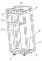
Fig. 1 is the structural representation of the utility model during as wardrobe.
Fig. 2 is the structural representation after of the present utility model folding.
In the drawings, 1, roller 2, transversal stretching section bar 3, slide fastener 4, laterally fixedly section bar 5, leg 6, vertically fixedly section bar 7, vertically flexible section bar 8, connector 9, hang clothing crossbeam 10, fixed cross beam 11, active pull rod 12, pull bar built-in beam 13, steady brace 14, fixed support.
The specific embodiment
As depicted in figs. 1 and 2, the utility model is achieved like this, it comprises roller 1, transversal stretching section bar 2, slide fastener 3, horizontal fixedly section bar 4, leg 5, vertical fixedly section bar 6, vertical flexible section bar 7, connector 8, hang clothing crossbeam 9, fixed cross beam 10, active pull rod 11, pull bar built-in beam 12, steady brace 13 and fixed support 14, its design feature is that front side and rear side are two parallel fixed supports 14, fixed support 14 bottoms that are positioned at front side are connected with two rollers 1, fixed support 14 bottoms that are positioned at rear side are fixedly connected with two legs 5, the opposite ends of two parallel fixed supports 14 all is connected by a telescoping mechanism, four ends of two parallel fixed supports 14 all are connected with the vertical fixedly lower end of section bar 6, vertical fixedly section bar 6 is connected with vertical flexible section bar 7 by slide fastener 4, be positioned at the upper end that connector 8 directly over fixed support 14 is connected to vertical flexible section bar 7, connector 8 one sides are connected with the fixed cross beam 10 parallel with fixed support 14, connector 8 opposite sides are connected with the telescoping mechanism vertical with fixed support 14, be connected with between two fixed cross beams 10 and hang clothing crossbeam 9, the lower end of steady brace 13 is fixedly connected on the fixed support 14 of front side, and the top of steady brace 13 is fixedly connected on pull bar built-in beam 12, and the two ends of pull bar built-in beam 12 are fixed on vertical fixedly section bar 6, and the top of steady brace 13 connects active pull rod 11, described telescoping mechanism is to be formed by connecting by slide fastener 3 by transversal stretching section bar 2 and horizontal fixedly section bar 4, one end of described extension clothing crossbeam 9 is hinged on the fixed cross beam 10 of a side, and the other end is buckled on the fixed cross beam 10 of opposite side.
Embodiment of the present utility model and use procedure are such, transversal stretching section bar 2 and vertical flexible section bar 7 are same section bar A, laterally fixedly section bar 4 and vertical fixedly section bar 6 are same section bar B, hang clothing crossbeam 9 and adopt hollow circular-tube, certain complete travelling also comprises the box frame of above-mentioned statement and canvas, coded lock and the slide fastener etc. of peripheral parcel with box wardrobe; When as the wardrobe state, as shown in Figure 1; When by wardrobe, being converted to the suitcase state, as shown in Figure 2, the operation use procedure is:
At first, take off an end of hanging clothing crossbeam 9, hang like this clothing crossbeam 9 automatic verticals and vertical fixedly section bar 6 is parallel, put into the pocket that one, canvas is specifically designed to these article of placement; Secondly, firmly four slide fasteners 3 on vertical direction are pressed, and, to pressing down connector 8, four vertical flexible section bars 7 are down moved along vertical fixedly section bar 6, until four slide fastener holes that slide fastener 3 stuck position are lower, position while placing; Again it was fallen, there is that face of pull bar to contact with ground, firmly four slide fasteners 3 are in a lateral direction pressed again, with defeating vertical fixedly section bar 6, make four transversal stretching section bars 2 on width transversely fixedly section bar 4 down move, until four slide fasteners 3 are stuck in another slide fastener hole, position while placing, promote, in active pull rod 11 indentation steady braces 13, to complete wardrobe to the suitcase transfer process.
Claims (3)
1. the box wardrobe of travelling, it comprises roller, the transversal stretching section bar, slide fastener, horizontal fixedly section bar, leg, vertical fixedly section bar, vertical flexible section bar, connector, hang the clothing crossbeam, fixed cross beam, active pull rod, the pull bar built-in beam, steady brace and fixed support, it is characterized in that front side and rear side are for two parallel fixed supports, the fixed support bottom that is positioned at front side is connected with two rollers, the fixed support bottom that is positioned at rear side is fixedly connected with two legs, two parallel support bracket fastened opposite ends all are connected by a telescoping mechanism, two parallel support bracket fastened four ends all are connected with the vertical fixedly lower end of section bar, vertical fixedly section bar is connected with vertical flexible section bar by slide fastener, be positioned at the upper end that connector directly over fixed support is connected to vertical flexible section bar, connector one side is connected with the fixed cross beam parallel with fixed support, the connector opposite side is connected with the telescoping mechanism vertical with fixed support, be connected with between two fixed cross beams and hang the clothing crossbeam, the lower end of steady brace is fixedly connected on the fixed support of front side, and the top of steady brace is fixedly connected on the pull bar built-in beam, and the two ends of pull bar built-in beam are fixed on vertical fixedly section bar, and the top of steady brace connects active pull rod.
2. the box wardrobe of a kind of travelling as claimed in claim 1, is characterized in that described telescoping mechanism is to be formed by connecting by slide fastener by transversal stretching section bar and horizontal fixedly section bar.
3. the box wardrobe of a kind of travelling as claimed in claim 1, is characterized in that an end of described extension clothing crossbeam is hinged on the fixed cross beam of a side, and the other end is buckled on the fixed cross beam of opposite side.
Priority Applications (1)
| Application Number | Priority Date | Filing Date | Title |
|---|---|---|---|
| CN201320415967.7U CN203378745U (en) | 2013-07-15 | 2013-07-15 | Case type wardrobe for travelling |
Applications Claiming Priority (1)
| Application Number | Priority Date | Filing Date | Title |
|---|---|---|---|
| CN201320415967.7U CN203378745U (en) | 2013-07-15 | 2013-07-15 | Case type wardrobe for travelling |
Publications (1)
| Publication Number | Publication Date |
|---|---|
| CN203378745U true CN203378745U (en) | 2014-01-08 |
Family
ID=49867285
Family Applications (1)
| Application Number | Title | Priority Date | Filing Date |
|---|---|---|---|
| CN201320415967.7U Expired - Fee Related CN203378745U (en) | 2013-07-15 | 2013-07-15 | Case type wardrobe for travelling |
Country Status (1)
| Country | Link |
|---|---|
| CN (1) | CN203378745U (en) |
Cited By (1)
| Publication number | Priority date | Publication date | Assignee | Title |
|---|---|---|---|---|
| CN105996484A (en) * | 2016-07-31 | 2016-10-12 | 合肥柏隆科技发展有限公司 | Wardrobe which can be changed into traveling bag |
-
2013
- 2013-07-15 CN CN201320415967.7U patent/CN203378745U/en not_active Expired - Fee Related
Cited By (1)
| Publication number | Priority date | Publication date | Assignee | Title |
|---|---|---|---|---|
| CN105996484A (en) * | 2016-07-31 | 2016-10-12 | 合肥柏隆科技发展有限公司 | Wardrobe which can be changed into traveling bag |
Similar Documents
| Publication | Publication Date | Title |
|---|---|---|
| US20150151771A1 (en) | Folding trolley | |
| WO2013000149A1 (en) | Table legs folding structure | |
| CN203378745U (en) | Case type wardrobe for travelling | |
| CN201330336Y (en) | Multilateral telescopic clothes rack | |
| CN202925343U (en) | Laundry rack convenient to fold and store | |
| CN205188648U (en) | Multi -functional outdoor push -and -pull clothes hanger that dries in air | |
| CN205625515U (en) | Multi -functional novel clothes hanger that dries in air | |
| CN208002293U (en) | A kind of folding trunk | |
| CN202112491U (en) | Multifunctional luggage case | |
| CN206238956U (en) | Telescopic printed matter displaying and accommodating mechanism | |
| CN205711456U (en) | A kind of multifunctional clothes hanger | |
| CN203885146U (en) | Floor type clothes rack | |
| CN203715958U (en) | Sliding guide rail-type clothes hanger | |
| CN203252095U (en) | Wardrobe trunk | |
| CN204743416U (en) | Folding bed body | |
| CN205251019U (en) | Novel take foldable mosquito net of storing function | |
| CN204363515U (en) | A kind of concertina type sliding push-pull mosquito net | |
| CN203633745U (en) | Retractable closet | |
| CN205795116U (en) | The vertical case and bag of self-supporting | |
| CN202043952U (en) | Mirror capable of being used for folding clothes | |
| CN205493221U (en) | Scalable campstool | |
| CN202658453U (en) | Improvement structure of folding clotheshorse | |
| CN205649248U (en) | Children's rail branch subassembly | |
| CN203493207U (en) | Width adjustable bedstead | |
| CN204623496U (en) | Retractable hand is pulled a cart |
Legal Events
| Date | Code | Title | Description |
|---|---|---|---|
| C14 | Grant of patent or utility model | ||
| GR01 | Patent grant | ||
| CF01 | Termination of patent right due to non-payment of annual fee |
Granted publication date: 20140108 Termination date: 20150715 |
|
| EXPY | Termination of patent right or utility model |