CN203375487U - Energy-gathered kitchen - Google Patents
Energy-gathered kitchen Download PDFInfo
- Publication number
- CN203375487U CN203375487U CN201320454025.XU CN201320454025U CN203375487U CN 203375487 U CN203375487 U CN 203375487U CN 201320454025 U CN201320454025 U CN 201320454025U CN 203375487 U CN203375487 U CN 203375487U
- Authority
- CN
- China
- Prior art keywords
- combustion chamber
- energy
- furnace core
- energy focusing
- fuel
- Prior art date
- Legal status (The legal status is an assumption and is not a legal conclusion. Google has not performed a legal analysis and makes no representation as to the accuracy of the status listed.)
- Expired - Fee Related
Links
Images

Classifications
-
- Y—GENERAL TAGGING OF NEW TECHNOLOGICAL DEVELOPMENTS; GENERAL TAGGING OF CROSS-SECTIONAL TECHNOLOGIES SPANNING OVER SEVERAL SECTIONS OF THE IPC; TECHNICAL SUBJECTS COVERED BY FORMER USPC CROSS-REFERENCE ART COLLECTIONS [XRACs] AND DIGESTS
- Y02—TECHNOLOGIES OR APPLICATIONS FOR MITIGATION OR ADAPTATION AGAINST CLIMATE CHANGE
- Y02B—CLIMATE CHANGE MITIGATION TECHNOLOGIES RELATED TO BUILDINGS, e.g. HOUSING, HOUSE APPLIANCES OR RELATED END-USER APPLICATIONS
- Y02B40/00—Technologies aiming at improving the efficiency of home appliances, e.g. induction cooking or efficient technologies for refrigerators, freezers or dish washers
Abstract
The utility model discloses an energy-gathered kitchen. The energy-gathered kitchen comprises a furnace core and an energy gathering body positioned on the top of the furnace core, wherein the furnace core comprises a furnace core outer layer and a furnace core inner layer; an air chamber is formed between the furnace core outer layer and the furnace core inner layer; an air inlet pipe is arranged at the bottom of the furnace core; a fire pipeline, a fuel pipeline and a spray nozzle are arranged in the furnace core inner layer; the fire pipeline and the fuel pipeline are connected to the furnace core inner layer and are staggered mutually; the spray nozzle is connected with the fuel pipeline; an air supply hole is formed in the furnace core inner layer; the center channel of the furnace is a fuel and air mixed combustion channel. The energy-gathered kitchen has the advantages that the fuel is fully combusted, so that the emission of carbon monoxide is reduced; the fire pipeline and the fuel pipeline are staggered, so that the ignition is safe; the energy gathering body is of a pot shape, so that heat is uniformly distributed to the bottom of pot; convex and concave heat radiating bodies are arranged uniformly, so that the heat is recycled; by the overall scheme, the energy saving efficiency of the energy-gathered kitchen can reach over 50 percent.
Description
Technical field
The utility model relates to the energy-conserving and environment-protective field, especially a kind of kitchen range transformation that is applicable to various commercial mechanism as: the energy focusing stove in hotel, restaurant, dining room etc.
Background technology
At present, the various commercial kitchen range, the cooking stove combustion chamber is for hypoxgia, and fuel can not fully burn, and makes cooking stove firepower deficiency and carbon monoxide toxic emission too high, causes the fuel consumption waste serious; The flame that cooking stove fuel produces, be, by blower fan oxygen supply supercharging, heat is directly delivered to the bottom of a pan, and heat energy can only once be utilized, and the waste of running off is serious, and combustion energy collection rate is low; Needs for burning, can not seal between the chamber of a kitchen range and the bottom of a pan fully, leaves space, and most of heats are along with unburnt mixed flue gas is discharged from space together, and heat waste is very large; Combustion energy collection rate is low; Igniter is dangerous, easily goes wrong.
Under the resource situation of current energy growing tension, need badly existing kitchen range are carried out to the transformation and upgrade replacement, to respond country, call, for national energy-saving and emission-reduction and the consumption of whole people's low-carbon (LC) are contributed.
The utility model content
The purpose of this utility model is to provide a kind of energy focusing stove, can make the abundant mixed combustion of fuel and air, and firepower is large, and carbon monoxide emission is few, can assemble flame heat energy, reaches the cumulative effect, the some fire safety.
For achieving the above object, embodiment of the present utility model adopts following technical scheme:
A kind of energy focusing stove, described energy focusing stove comprises combustion chamber and is positioned at the cumulative body at combustion chamber top, described combustion chamber comprises that combustion chamber is outer, the combustion chamber internal layer, form air chamber between described combustion chamber skin and combustion chamber internal layer, blast pipe is arranged at described combustion chamber bottom, described combustion chamber internal layer is provided with kindling material pipeline, fuel channel and shower nozzle, described kindling material pipeline and fuel channel are connected on the combustion chamber internal layer and mutually stagger, described shower nozzle is connected with fuel channel, described combustion chamber inner layer wall is provided with air supply hole, and described combustion chamber central passage is fuel and air mixed combustion passage.
According to an aspect of the present utility model, wherein, described cumulative body is provided with concavo-convex heat radiator.
According to an aspect of the present utility model, wherein, described concavo-convex heat radiator material is the high-temperature alloy material.
According to an aspect of the present utility model, wherein, described cumulative body is pot shape.
According to an aspect of the present utility model, wherein, described cumulative body center is provided with burning gallery, and diameter is the outer inner diameter of combustion chamber.
According to an aspect of the present utility model, wherein, in described cumulative body burning gallery, be provided with fire guiding ring.
According to an aspect of the present utility model, wherein, described combustion chamber skin is fastening by bolt and combustion chamber internal layer.
According to an aspect of the present utility model, wherein, the material of described cumulative body and fire guiding ring is the high-temperature alloy material.
According to an aspect of the present utility model, wherein, described kindling material pipeline staggers into 10 ° to 180 ° angles with fuel channel.
According to an aspect of the present utility model, wherein, described combustion chamber material is the pig iron.
Scheme of the present utility model can be reached following effect: combustion chamber band fuel under high pressure output nozzle, undergrate blast pipe, combustion chamber air supply hole, make air supply and fuel output aerodynamically scientific matching, fully mix, can make fuel be fully burned, reduce carbon monoxide emission, environment protecting is good; The setting of staggering of kindling material pipeline and fuel channel, make to light a fire safer; The cumulative body, by the design of pot shape, suits the bottom of a pan profile, suits closely and makes flame heat regulating be difficult for scattering and disappearing, and can be uniformly dispersed below, the bottom of a pan; Be with concavo-convex heat radiation point and heat circulation system design on the cumulative body, can effectively absorb heat, store heat, release heat, reach the cumulative effect, and heat is repeatedly recycled; Combustion chamber adopts the pig iron to make, long service life; The cumulative body adopts high-temperature alloy material, cumulative better effects if, and long service life, easy disassembling.Overall plan can allow the energy-saving efficiency of energy focusing stove reach more than 50%.
The accompanying drawing explanation
In order to be illustrated more clearly in the technical scheme in the utility model embodiment, below will the accompanying drawing of required use in embodiment be briefly described, apparently, accompanying drawing in the following describes is only embodiment more of the present utility model, for those of ordinary skills, under the prerequisite of not paying creative work, can also obtain according to these accompanying drawings other accompanying drawing.
Fig. 1 is a kind of energy focusing stove general assembly schematic diagram of the present utility model;
The stove core structure schematic diagram that Fig. 2 is a kind of energy focusing stove of the present utility model;
The combustion chamber endothecium structure schematic diagram that Fig. 3 is combustion chamber in Fig. 2;
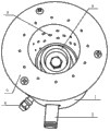
The top view of a kind of energy focusing stove that Fig. 4 is the utility model embodiment bis-.
The specific embodiment
Below in conjunction with the accompanying drawing in the utility model embodiment, the technical scheme in the utility model embodiment is clearly and completely described, obviously, described embodiment is only the utility model part embodiment, rather than whole embodiment.Embodiment based in the utility model, those of ordinary skills are not making under the creative work prerequisite the every other embodiment obtained, and all belong to the scope of the utility model protection.
Embodiment mono-
As Fig. 1, Fig. 2, shown in Fig. 3, described energy focusing stove comprises combustion chamber 1 and cumulative body 2, cumulative body 2 is positioned at the combustion chamber top, described combustion chamber 1 comprises combustion chamber skin 7, combustion chamber internal layer 6, form air chamber between described combustion chamber outer 7 and combustion chamber internal layer 6, blast pipe 5 is arranged at described combustion chamber 1 bottom, described combustion chamber internal layer 6 is provided with kindling material pipeline 4, fuel channel 3 and shower nozzle 8, described kindling material pipeline 4 and fuel channel 3 are connected on combustion chamber internal layer 6 and mutually stagger, described shower nozzle 8 is connected with fuel channel 3, described combustion chamber internal layer 6 walls are provided with air supply hole 9, described combustion chamber 1 central passage is fuel and air mixed combustion passage.
Wherein, undergrate blast pipe 5, combustion chamber air supply hole 9, make air supply and fuel output aerodynamically scientific matching, fully is blended in combustion chamber 1 center mixed combustion passage, can make fuel be fully burned, and reduces carbon monoxide emission, and environment protecting is good; The use of cumulative body 2, can make heat not scatter and disappear, and can absorb heat, release heat, reaches the cumulative effect; The angled setting of staggering of kindling material pipeline 4 and fuel channel 3, make to light a fire safer; Shower nozzle 8 makes the fuel ejection, and with the abundant mixed combustion of air entered by air supply hole 9, when firepower is large, burning is more abundant.
Embodiment bis-
As Fig. 1, Fig. 2, Fig. 3, shown in Fig. 4, described energy focusing stove comprises combustion chamber 1 and cumulative body 2, cumulative body 2 is positioned at the combustion chamber top, described combustion chamber 1 comprises combustion chamber skin 7, combustion chamber internal layer 6, form air chamber between described combustion chamber outer 7 and combustion chamber internal layer 6, blast pipe 5 is arranged at described combustion chamber 1 bottom, described combustion chamber internal layer 6 is provided with kindling material pipeline 4, fuel channel 3 and shower nozzle 8, described kindling material pipeline 4 and fuel channel 3 are connected on combustion chamber internal layer 6 and mutually stagger, described shower nozzle 8 is connected with fuel channel 3, described combustion chamber internal layer 6 walls are provided with air supply hole 9, described combustion chamber 1 central passage is fuel and air mixed combustion passage.Described cumulative body 2 is pot shape, and which is provided with concavo-convex heat radiator 10, and centre is provided with burning gallery 11, and burning gallery 11 diameter are outer 7 inner diameters of combustion chamber.
Wherein, undergrate blast pipe 5, combustion chamber air supply hole 9, make air supply and fuel output aerodynamically scientific matching, fully is blended in combustion chamber 1 center mixed combustion passage, can make fuel be fully burned, and reduces carbon monoxide emission, and environment protecting is good; The use of cumulative body 2, can make heat not scatter and disappear, and can absorb heat, release heat, reaches the cumulative effect; Kindling material pipeline 4 staggers into 10 ° to 180 ° angles with fuel channel 3, makes to light a fire safer; Shower nozzle 8 makes the fuel ejection, and with the abundant mixed combustion of air entered by air supply hole 9, when firepower is large, burning is more abundant; Cumulative body 2 adopts the design of pot shape simultaneously, more suit form of pot bottom, make even flame be distributed in the bottom of a pan, heat all is lockable, and the concavo-convex heat radiator 10 on it can absorb heat, storing heat, release heat, and adopts the circulation canal design, heat recycles, reach the cumulative effect, the setting of burning gallery 11, make flame heat energy more concentrated.
In actual applications, usually add fire guiding ring 12 in burning gallery 11, make flame more concentrated, heat is also more concentrated; Combustion chamber 1 adopts the pig iron to make usually, and combustion chamber internal layer 6 and combustion chamber outer 7 is by bolted, and the scleroid while, more ability is lived high temperature, improves service life; Cumulative body 2 adopts the manufacture of high-temperature alloy material, and fire guiding ring 12 also adopts the high-temperature alloy material, and both materials more easily absorb heat, release heat, and heat is concentrated, and reaches the cumulative effect, and durable in use, long service life.
By above embodiment, scheme of the present utility model can be reached following effect: combustion chamber band fuel under high pressure output nozzle, undergrate blast pipe, combustion chamber air supply hole, make air supply and fuel output aerodynamically scientific matching, fully mix, can make fuel be fully burned, reduce carbon monoxide emission, environment protecting is good; The setting of staggering of kindling material pipeline and fuel channel, make to light a fire safer; The cumulative body, by the design of pot shape, suits the bottom of a pan profile, suits closely and makes flame heat regulating be difficult for scattering and disappearing, and can be uniformly dispersed below, the bottom of a pan; Be with concavo-convex heat radiation point and heat circulation system design on the cumulative body, can effectively absorb heat, store heat, release heat, reach the cumulative effect, and heat is repeatedly recycled; Combustion chamber adopts the pig iron to make, long service life; The cumulative body adopts high-temperature alloy material, cumulative better effects if, and long service life, easy disassembling.Overall plan can allow the energy-saving efficiency of energy focusing stove reach more than 50%.
The above; it is only the specific embodiment of the present utility model; but protection domain of the present utility model is not limited to this; the technical staff of any skilled is in the disclosed technical scope of the utility model; the variation that can expect easily or replacement, within all should being encompassed in protection domain of the present utility model.Therefore, protection domain of the present utility model should be as the criterion with the protection domain of described claim.
Claims (10)
1. an energy focusing stove, it is characterized in that, described energy focusing stove comprises combustion chamber and is positioned at the cumulative body at combustion chamber top, described combustion chamber comprises that combustion chamber is outer, the combustion chamber internal layer, form air chamber between described combustion chamber skin and combustion chamber internal layer, blast pipe is arranged at described combustion chamber bottom, described combustion chamber internal layer is provided with kindling material pipeline, fuel channel and shower nozzle, described kindling material pipeline and fuel channel are connected on the combustion chamber internal layer and mutually stagger, described shower nozzle is connected with fuel channel, described combustion chamber inner layer wall is provided with air supply hole, and described combustion chamber central passage is fuel and air mixed combustion passage.
2. energy focusing stove according to claim 1, is characterized in that, described cumulative body is provided with concavo-convex heat radiator.
3. energy focusing stove according to claim 2, is characterized in that, described concavo-convex heat radiator material is the high-temperature alloy material.
4. according to the described energy focusing stove of one of claims 1 to 3, it is characterized in that, described cumulative body is pot shape.
5. energy focusing stove according to claim 4, is characterized in that, described cumulative body center is provided with burning gallery, and diameter is the outer inner diameter of combustion chamber.
6. energy focusing stove according to claim 5, is characterized in that, in described cumulative body burning gallery, is provided with fire guiding ring.
7. energy focusing stove according to claim 6, is characterized in that, described combustion chamber skin is fastening by bolt and combustion chamber internal layer.
8. energy focusing stove according to claim 7, is characterized in that, the material of described cumulative body and fire guiding ring is the high-temperature alloy material.
9. energy focusing stove according to claim 8, is characterized in that, described kindling material pipeline staggers into 10 ° to 180 ° angles with fuel channel.
10. energy focusing stove according to claim 9, is characterized in that, described combustion chamber material is the pig iron.
Priority Applications (1)
| Application Number | Priority Date | Filing Date | Title |
|---|---|---|---|
| CN201320454025.XU CN203375487U (en) | 2013-07-26 | 2013-07-26 | Energy-gathered kitchen |
Applications Claiming Priority (1)
| Application Number | Priority Date | Filing Date | Title |
|---|---|---|---|
| CN201320454025.XU CN203375487U (en) | 2013-07-26 | 2013-07-26 | Energy-gathered kitchen |
Publications (1)
| Publication Number | Publication Date |
|---|---|
| CN203375487U true CN203375487U (en) | 2014-01-01 |
Family
ID=49838014
Family Applications (1)
| Application Number | Title | Priority Date | Filing Date |
|---|---|---|---|
| CN201320454025.XU Expired - Fee Related CN203375487U (en) | 2013-07-26 | 2013-07-26 | Energy-gathered kitchen |
Country Status (1)
| Country | Link |
|---|---|
| CN (1) | CN203375487U (en) |
Cited By (2)
| Publication number | Priority date | Publication date | Assignee | Title |
|---|---|---|---|---|
| CN105066186A (en) * | 2015-09-18 | 2015-11-18 | 施美琴 | Gas energy-saving stove |
| CN105091038A (en) * | 2015-09-18 | 2015-11-25 | 施美琴 | Energy-saving and environment-friendly gas stove |
-
2013
- 2013-07-26 CN CN201320454025.XU patent/CN203375487U/en not_active Expired - Fee Related
Cited By (2)
| Publication number | Priority date | Publication date | Assignee | Title |
|---|---|---|---|---|
| CN105066186A (en) * | 2015-09-18 | 2015-11-18 | 施美琴 | Gas energy-saving stove |
| CN105091038A (en) * | 2015-09-18 | 2015-11-25 | 施美琴 | Energy-saving and environment-friendly gas stove |
Similar Documents
| Publication | Publication Date | Title |
|---|---|---|
| CN105674268B (en) | energy-saving gas burner | |
| CN105757666A (en) | Tri-cyclic combined full direct injection type fire distributor applied to household gas stove combustor | |
| CN203375487U (en) | Energy-gathered kitchen | |
| CN204786593U (en) | Adopt novel secondary air to replenish gas cooking utensils of passageway | |
| CN201964411U (en) | High-power double-cyclone burning semi-premix gas burner | |
| CN203718842U (en) | Frying oven premixed furnace end without stinging eyes | |
| CN203442831U (en) | Burner of household gas cooker | |
| CN203718774U (en) | Frying-stove pre-mixing hollow furnace end capable of preventing sting in eyes | |
| CN104154537B (en) | Oxygen gas swirl combustion device is joined in a kind of front end | |
| CN203442815U (en) | Burner of household gas cooker | |
| CN208253582U (en) | A kind of heat build-up catalytic type multi-head burner | |
| CN202419711U (en) | Large-hearth biomass burner | |
| CN205606548U (en) | Gas burning energy saving burner | |
| CN205641015U (en) | Household gas range combustor with one -piece type full formula distributor structure of directly spouting in third ring | |
| CN205102184U (en) | Young stove of energy -conserving a kind of deep pot | |
| CN204268478U (en) | There is the injector of gas distribution chamber | |
| CN204026754U (en) | Energy-saving safe large stove | |
| CN204987104U (en) | Energy -concerving and environment -protective type gas stove | |
| CN205065695U (en) | Full -automatic biomass combustion furnace furnace body | |
| CN204962871U (en) | Novel energy saving kitchen range | |
| CN202328394U (en) | Dual-intake pipe gas furnace | |
| CN204268469U (en) | Bull direct spray type hurner | |
| CN103343972B (en) | A kind of burner apparatus for gas ranges | |
| CN208295916U (en) | A kind of energy-saving and environmental protection type low Nox burner | |
| CN210107390U (en) | Full premix burner |
Legal Events
| Date | Code | Title | Description |
|---|---|---|---|
| C14 | Grant of patent or utility model | ||
| GR01 | Patent grant | ||
| CF01 | Termination of patent right due to non-payment of annual fee |
Granted publication date: 20140101 Termination date: 20160726 |
|
| CF01 | Termination of patent right due to non-payment of annual fee |