CN203321347U - High-load drill rod and raise-boring machine comprising drill rod - Google Patents
High-load drill rod and raise-boring machine comprising drill rod Download PDFInfo
- Publication number
- CN203321347U CN203321347U CN2013201071861U CN201320107186U CN203321347U CN 203321347 U CN203321347 U CN 203321347U CN 2013201071861 U CN2013201071861 U CN 2013201071861U CN 201320107186 U CN201320107186 U CN 201320107186U CN 203321347 U CN203321347 U CN 203321347U
- Authority
- CN
- China
- Prior art keywords
- thread
- drill rod
- cone thread
- drilling rod
- inside tapered
- Prior art date
- Legal status (The legal status is an assumption and is not a legal conclusion. Google has not performed a legal analysis and makes no representation as to the accuracy of the status listed.)
- Expired - Fee Related
Links
Images


Abstract
The utility model discloses a high-load drill rod and a raise-boring machine comprising the drill rod. The high-load drill rod comprises a hollow drill rod body, wherein a male joint and a female joint which are mutually matched are arranged at the two ends of the hollow drill rod body; both the male joint and the female joint adopt hollow structures; an external cone thread axially extending is arranged on the outer side wall of the male joint; an internal cone thread axially extending is arranged on the inner side wall of the female joint; the thread angles of the outer cone thread and the inner cone thread are 60 degrees, and the ratio of the taper of the outer cone thread to that of the inner cone thread is (1:7)-(1:12); a bearing flank angle alpha 1 and a buckling flank angle beta 1 are formed on the outer cone thread; the inner cone thread and the outer cone thread are correspondingly arranged; a bearing flank angle alpha 2 and a buckling flank angle beta 2 are formed on the inner cone thread; the bearing flank angles alpha 1 and alpha 2 are equal to be within the range not less than 10 degrees and not more than 20 degrees, the buckling flank angles beta 1 and beta 2 are equal to be within the range not less than 40 degrees and not more than 50 degrees, and the sum of the alpha 1 and the beta 1 and that of the alpha 2 and the beta 2 are equal to be 60 degrees. The high-load drill rod disclosed by the utility mode can bear large axial tensile force and torque, and is suitable for large raise-boring machines.
Description
Technical field
The utility model relates to the mining machinery field, relates in particular to a kind of high capacity drilling rod, and the utility model also relates to a kind of raise boring machine.
Background technology
Raise boring machine is as a kind of important construction machinery in mining machinery, in being arranged, the stable shaft construction of bottom haulage drift, geological conditions is used widely, it is mainly the motor driving oil pump drive hydraulic motor by rig, and utilize hydraulic power that moment of torsion is passed to drilling system, drive drilling rod and bit, hobboing cutter on guide hole drill bit or reaming bit, under the effect of the pressure of the drill, is done pure rolling or microdisplacement along the bottom rock work plane; Simultaneously the main frame oil cylinder produces axially draws, pressure also acts on guide hole drill bit or reaming bit by unit head, drilling rod, the hobboing cutter of guide hole drill bit is rolled under the pressure of the drill effect, produce shock loading, make the hobboing cutter tooth produce impact, extruding and shear action, fractured rock to rock.
The current joint screw thread of raise boring machine drilling rod in the world adopts the taper joint thread connecting mode of American Petroleum Institute (API) (API) standard more, this screw thread is regular button cone triangle thread form, its tooth form angle is 60 °, tapering is 1:6, the tooth distance is 6.35mm, this joint screw thread is petroleum drilling and then design, it is mainly specific is easily manufactured, but anti-twisting property is little, in the application of raise boring machine tool joint thread, often cause facing distortion and whole fracture in the situation that bear larger axis to pulling force and moment of torsion, become the bottleneck of restriction raise boring machine to the large well depth future development of high moment of torsion.
Therefore, provide a kind of and can bear large axially pulling force and moment of torsion, the high capacity drilling rod that is applicable to large-scale raise boring machine is the technical problem that those skilled in the art need solution badly.
The utility model content
A purpose of the present utility model is to provide a kind ofly can bear large axially pulling force and moment of torsion, is applicable to the high capacity drilling rod of large-scale raise boring machine, and another purpose of the present utility model is to provide a kind of raise boring machine.
In order to realize above-mentioned first purpose, the utility model provides a kind of high capacity drilling rod, for rig, be particularly useful for raise boring machine, the drilling rod body that comprises hollow, the two ends of hollow body are provided with male joint and the female joint of mutual coupling, described male joint and female joint are hollow structure, there is axially extended outer cone thread on the lateral wall of male joint, there is axially extended inside tapered thread on the inside wall of female joint, the tooth form angle of described outer cone thread and described inside tapered thread is 60 °, and the tapering of described outer cone thread and described inside tapered thread is 1:7 ~ 1:12; Described outer cone thread has carrying tooth side angle α
1With enter the buckle teeth side angle
1, 10 °≤α wherein
1≤ 20 °, 40 °≤β
1≤ 50 °, α
1+ β
1=60 °; The setting corresponding to described outer cone thread of described inside tapered thread, described inside tapered thread has carrying tooth side angle α
2With enter the buckle teeth side angle
2, 10 °≤α wherein
2≤ 20 °, 40 °≤β
2≤ 50 °, α
2+ β
2=60 °, and α
1=α
2, β
1=β
2.
Preferably, described outer, inside tapered thread tooth is apart from be 12.7mm, described outward, the tapering of inside tapered thread is 1:8.
Preferably, described helical pitch outer, inside tapered thread is 25.4mm.
Preferably, the carrying tooth side angle α of described outer, inside tapered thread
1=α
2=15 °, described outer, inside tapered thread enter the buckle teeth side angle
1=β
2=45 °.
In order to realize above-mentioned second purpose, the utility model also provides a kind of raise boring machine, comprises above-mentioned high capacity drilling rod.
Compared with prior art, high capacity drilling rod provided by the utility model, by increasing the ridge distance, strengthened shear strength and bending strength, and improved the ability to bear of axial tension; By improving tapering, improved the tolerances of axial tension; By increasing helical pitch, increased lead angle, thereby improved anti-twisting property; Screw thread bear face and angle that horizontal plane is is large, after internal and external threads screws, it is large that it bears area, improved the ability that bears of drilling rod.
Compared with prior art, raise boring machine provided by the utility model comprises above-mentioned high capacity drilling rod, and the technique effect of its technique effect and above-mentioned high capacity drilling rod is basic identical, repeats no more herein.
The accompanying drawing explanation
Fig. 1 is the structural representation of a kind of embodiment of a kind of high capacity drilling rod that the utility model proposes;
Fig. 2 is the taper thread thread form schematic diagram of a kind of embodiment of a kind of high capacity drilling rod that the utility model proposes;
Fig. 3 is that buttress thread and the triangle thread drill rod thread of a kind of embodiment of a kind of high capacity drilling rod that the utility model proposes launches sketch.
The specific embodiment
A purpose of the present utility model is to provide a kind ofly can bear large axially pulling force and moment of torsion, is applicable to the high capacity drilling rod of large-scale raise boring machine, and another purpose of the present utility model is to provide a kind of raise boring machine.
In order to make those skilled in the art understand better the technical solution of the utility model; below in conjunction with accompanying drawing, the utility model is described in detail; the description of this part is only exemplary and explanatory, should any restriction not arranged to protection domain of the present utility model.
Please refer to Fig. 1 and Fig. 2, in one embodiment, a kind of high capacity drilling rod provided by the utility model, for rig, be particularly useful for raise boring machine, the drilling rod body that comprises hollow, the two ends of hollow body are provided with male joint and the female joint of mutual coupling, described male joint and female joint are hollow structure, there is axially extended outer cone thread on the lateral wall of male joint, there is axially extended inside tapered thread on the inside wall of female joint, the tooth form angle of described outer cone thread and described inside tapered thread is 60 °, outside described, inside tapered thread tooth distance is 12.7mm, tapering is 1:8, helical pitch is 25.4mm, described outer cone thread has carrying tooth side angle α
1with enter the buckle teeth side angle
1, the setting corresponding to described outer cone thread of described inside tapered thread, described inside tapered thread has carrying tooth side angle α
2with enter the buckle teeth side angle
2, the carrying tooth side angle α of wherein said outer, inside tapered thread
1=α
2=15 °, described outer, inside tapered thread enter the buckle teeth side angle
1=β
2=45 °.
As shown in Figure 3, upper and lower two figure are respectively high capacity drilling rod taper thread and the regular button cone of API oil angular thread spread of single circle blade sketch, and the shear strength of every circle form of thread is
 , bending strength is
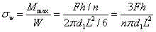 , in formula
 The axial tension be subject to for drilling rod,
 For the effective thread number of turns,
 For height of thread,
 For the screw thread path,
 For the screw thread tooth base width; Learn that by calculating high capacity drilling rod taper thread shear strength is higher in identical height of thread and tooth form angle situation, bending strength strengthens greatly; Drilling rod bears moment of torsion
 Effect, by
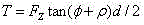 Get final product to obtain the suffered axial tension of drilling rod
, in formula
Get final product to obtain the suffered axial tension of drilling rod
, in formula
 With
Be respectively lead angle and screw thread equivalent friction angle; Due to this high capacity drilling rod taper thread lead angle, to bore angular thread than API much larger, in the situation that apply same torque, its axial thrust load
With
Be respectively lead angle and screw thread equivalent friction angle; Due to this high capacity drilling rod taper thread lead angle, to bore angular thread than API much larger, in the situation that apply same torque, its axial thrust load
 Be only 1/3 ~ 1/4 of API cone angular thread, improved exponentially the torsional property of drilling rod.
Therefore, high capacity drilling rod provided by the utility model, by increasing the ridge distance, strengthened shear strength and bending strength, and improved the ability to bear of axial tension; By improving tapering, improved the tolerances of axial tension; By increasing helical pitch, increased lead angle, thereby improved anti-twisting property; Screw thread bear face and angle that horizontal plane is is large, after internal and external threads screws, it is large that it bears area, improved the ability that bears of drilling rod.
It should be noted that, in this article, term " comprises ", " comprising " or its any other variant are intended to contain comprising of nonexcludability, thereby make the process, method, article or the equipment that comprise a series of key elements not only comprise which key element, but also comprise other key elements of clearly not listing, or also be included as the intrinsic key element of this process, method, article or equipment.In the situation that not more restrictions, the key element limited by statement " comprising ... ", and be not precluded within process, method, article or the equipment that comprises key element and also have other identical element.
Applied specific case herein principle of the present utility model and embodiment are set forth, the explanation of above embodiment is just for helping to understand method of the present utility model and core concept thereof.The above is only preferred embodiment of the present utility model, should be understood that, finiteness due to literal expression, and objectively there is unlimited concrete structure, for those skilled in the art, under the prerequisite that does not break away from the utility model principle, can also make some improvement, retouching or variation, also above-mentioned technical characterictic can be combined by rights; These improve retouching, change or combination, or without improving, the design of utility model and technical scheme are directly applied to other occasion, all should be considered as protection domain of the present utility model.
Claims (5)
1. a high capacity drilling rod, for rig, the drilling rod body that comprises hollow, the two ends of hollow body are provided with male joint and the female joint of mutual coupling, and described male joint and female joint are hollow structure, have axially extended outer cone thread on the lateral wall of male joint, there is axially extended inside tapered thread on the inside wall of female joint, the tooth form angle of described outer cone thread and described inside tapered thread is 60 °, it is characterized in that, the tapering of described outer cone thread and described inside tapered thread is 1:7 ~ 1:12; Described outer cone thread has carrying tooth side angle α
1With enter the buckle teeth side angle
1, 10 °≤α wherein
1≤ 20 °, 40 °≤β
1≤ 50 °, α
1+ β
1=60 °; The setting corresponding to described outer cone thread of described inside tapered thread, described inside tapered thread has carrying tooth side angle α
2With enter the buckle teeth side angle
2, 10 °≤α wherein
2≤ 20 °, 40 °≤β
2≤ 50 °, α
2+ β
2=60 °, and α
1=α
2, β
1=β
2.
2. high capacity drilling rod according to claim 1, is characterized in that, described outer, inside tapered thread tooth is apart from be 12.7mm, described outward, the tapering of inside tapered thread is 1:8.
3. high capacity drilling rod according to claim 1, is characterized in that, described helical pitch outer, inside tapered thread is 25.4mm.
4. according to the described high capacity drilling rod of claim 1-3 any one, it is characterized in that the carrying tooth side angle α of described outer, inside tapered thread
1=α
2=15 °, described outer, inside tapered thread enter the buckle teeth side angle
1=β
2=45 °.
5. a raise boring machine, is characterized in that, comprises the described high capacity drilling rod of claim 1-4 any one.
Priority Applications (1)
| Application Number | Priority Date | Filing Date | Title |
|---|---|---|---|
| CN2013201071861U CN203321347U (en) | 2013-03-09 | 2013-03-09 | High-load drill rod and raise-boring machine comprising drill rod |
Applications Claiming Priority (1)
| Application Number | Priority Date | Filing Date | Title |
|---|---|---|---|
| CN2013201071861U CN203321347U (en) | 2013-03-09 | 2013-03-09 | High-load drill rod and raise-boring machine comprising drill rod |
Publications (1)
| Publication Number | Publication Date |
|---|---|
| CN203321347U true CN203321347U (en) | 2013-12-04 |
Family
ID=49660710
Family Applications (1)
| Application Number | Title | Priority Date | Filing Date |
|---|---|---|---|
| CN2013201071861U Expired - Fee Related CN203321347U (en) | 2013-03-09 | 2013-03-09 | High-load drill rod and raise-boring machine comprising drill rod |
Country Status (1)
| Country | Link |
|---|---|
| CN (1) | CN203321347U (en) |
Cited By (3)
| Publication number | Priority date | Publication date | Assignee | Title |
|---|---|---|---|---|
| CN103114816A (en) * | 2013-03-09 | 2013-05-22 | 长沙创远高新机械有限责任公司 | High load drill stem and raise boring machine with the same |
| CN106499342A (en) * | 2016-12-20 | 2017-03-15 | 宁夏天地奔牛实业集团有限公司 | On to anti-well rig reaming bit and starter erecting device and method |
| EP3141689B1 (en) | 2015-09-11 | 2019-12-04 | Sysbohr GmbH Bohrtechnik für den Spezialtiefbau | Threaded connection and drilling rod having a threaded connection |
-
2013
- 2013-03-09 CN CN2013201071861U patent/CN203321347U/en not_active Expired - Fee Related
Cited By (3)
| Publication number | Priority date | Publication date | Assignee | Title |
|---|---|---|---|---|
| CN103114816A (en) * | 2013-03-09 | 2013-05-22 | 长沙创远高新机械有限责任公司 | High load drill stem and raise boring machine with the same |
| EP3141689B1 (en) | 2015-09-11 | 2019-12-04 | Sysbohr GmbH Bohrtechnik für den Spezialtiefbau | Threaded connection and drilling rod having a threaded connection |
| CN106499342A (en) * | 2016-12-20 | 2017-03-15 | 宁夏天地奔牛实业集团有限公司 | On to anti-well rig reaming bit and starter erecting device and method |
Similar Documents
| Publication | Publication Date | Title |
|---|---|---|
| CN203321347U (en) | High-load drill rod and raise-boring machine comprising drill rod | |
| CN103114816A (en) | High load drill stem and raise boring machine with the same | |
| CN202900044U (en) | Double stabilizer prebuckling dynamics pendulum drilling assembly | |
| CN203655163U (en) | Rotary drilling rig and variable diameter cylinder drill thereof | |
| CN204225782U (en) | A kind of large aperture, coal seam deep drill Anti-inclining drilling rod | |
| CN104131787A (en) | Tower-type drill bit | |
| CN202882790U (en) | Anti-drop joint structure of reinforced screw drill | |
| CN103015913A (en) | Exploration drill rod thread structure with 12-3/4-inch ultra-large caliber | |
| CN205778593U (en) | A kind of anti-galling drilling tool thread joint | |
| CN212406586U (en) | Multi-branch yield tool pipe internal guiding tool | |
| CN111852335B (en) | Guiding tool in multi-branch production increasing tool pipe | |
| CN204040936U (en) | The female adapter of petroleum pipeline direct linkage type | |
| CN203321360U (en) | Stabilizer bar structure and raise boring machine comprising stabilizer bar structure | |
| CN205558808U (en) | Oil development pilot scale prospecting bit ground device | |
| CN202832279U (en) | Integral helical-groove directional drill pipe | |
| CN203097716U (en) | Combined drill column device for drilling of directional well | |
| CN204040937U (en) | The male connection of petroleum pipeline direct linkage type | |
| CN201771446U (en) | Spiral drill collar with thickened middle of pipe body | |
| CN113482684B (en) | Tunnel anchor rod capable of monitoring stress and strain of tunnel | |
| CN103015916A (en) | Integral type directional drill rod provided with helical groove | |
| CN202055769U (en) | Threaded connection structure of rope drill rods | |
| CN204163652U (en) | A kind of three rib drill stems | |
| CN106884616A (en) | A kind of driller for oil exploration | |
| CN203822161U (en) | Connecting device of drill bit | |
| CN103302516B (en) | Interior four directions inserted joint pipe female fixing device for drilling |
Legal Events
| Date | Code | Title | Description |
|---|---|---|---|
| C14 | Grant of patent or utility model | ||
| GR01 | Patent grant | ||
| CF01 | Termination of patent right due to non-payment of annual fee |
Granted publication date: 20131204 Termination date: 20180309 |
|
| CF01 | Termination of patent right due to non-payment of annual fee |