CN203320979U - Reinforcing device of high-strength bolt hoop bracket - Google Patents
Reinforcing device of high-strength bolt hoop bracket Download PDFInfo
- Publication number
- CN203320979U CN203320979U CN2013204122460U CN201320412246U CN203320979U CN 203320979 U CN203320979 U CN 203320979U CN 2013204122460 U CN2013204122460 U CN 2013204122460U CN 201320412246 U CN201320412246 U CN 201320412246U CN 203320979 U CN203320979 U CN 203320979U
- Authority
- CN
- China
- Prior art keywords
- strength bolt
- steel
- anchor ear
- bracing means
- former frame
- Prior art date
- Legal status (The legal status is an assumption and is not a legal conclusion. Google has not performed a legal analysis and makes no representation as to the accuracy of the status listed.)
- Expired - Fee Related
Links
Images

Abstract
The utility model discloses a reinforcing device of a high-strength bolt hoop bracket. The reinforcing device of the high-strength bolt hoop bracket comprises an original frame structural beam (8), an original frame structural column (9) and a steel bracket (3), the original structural column (9) is provided with a steel hoop beam (1), the steel hoop beam (1) and the steel bracket (3) are fixedly connected through a high-strength bolt (2), a force transforming assembly is arranged at the lower end of the original frame structural beam (8), and the force transforming assembly and the top face of the steel bracket (3) are fixedly connected through a bolt assembly (4). The reinforcing device of the high-strength bolt hoop bracket is used for reinforcing constructional engineering with concrete frame beams which are insufficient in bearing capacity, the reinforcing device gets rid of wet construction, reinforcing construction is convenient, the construction period is short, mechanical properties are reliable, and good economic benefit can be generated.
Description
Technical field
The utility model relates to the structural strengthening technology of civil engineering, while referring more particularly to the concrete frame beam Lack of support, and a kind of high-strength bolt anchor ear bracket bracing means adopted.
Background technology
Due to many reasons such as structure is aging, use Functional changes, cause the Lack of support of reinforced concrete beam, need to carry out structural strengthening, in existing reinforcing technique, more employing is rearmounted chemical bolt or bar planting on the concrete frame trestle, then steel joist or concreting are set, form superposed beam.
Existing reinforcing technique, exist complicated construction technique, wet trade is long in time limit, construction period affects building problems such as use.
Summary of the invention
The technical problems to be solved in the utility model is to provide that a kind of construction technology is simple, the wet trade duration is short, construction period do not affect building and use and the good high-strength bolt anchor ear bracket bracing means of consolidation effect.
In order to solve the problems of the technologies described above, the utility model provides a kind of high-strength bolt anchor ear bracket bracing means, comprise former frame structural beam, former frame construction post and steel corbel, described former frame construction post is provided with the stirrup beam, described stirrup beam is fixedly connected with by high-strength bolt with steel corbel, described former frame structural beam lower end is provided with the power transmission assembly, and described power transmission assembly is fixedly connected with by bolt assembly with the end face of steel corbel.
As further improvement of the utility model, described stirrup beam or steel corbel are provided with bolt hole, and described bolt hole and high-strength bolt are suitable, and the bolt hole on described stirrup beam and steel corbel is symmetrical.
As further improvement of the utility model, described high-strength bolt is provided with 3-6.
As further improvement of the utility model, described power transmission assembly comprises steel joist, rubber sheet gasket and U-shaped steel plate, the span of the described U-shaped steel plate in lower end that described U-shaped steel plate is located at former frame structural beam is consistent with the width of former frame structural beam, be provided with rubber sheet gasket between described steel joist and U-shaped steel plate, rubber sheet gasket is preferentially selected ageing-resistant vulcanie.
As further improvement of the utility model, the antiarch that described steel joist is 1/1000.
As further improvement of the utility model, the end face of described steel joist or steel corbel is provided with bolt hole, and described bolt hole and bolt assembly are suitable.
As further improvement of the utility model, the thickness of U-shaped steel plate is 2mm.
Compare with existing structure, the utlity model has following advantage:
(1), the utility model construction technology is simple, easy to operate, the duration is short.
(2), the utility model realizes all dry operations, avoids wet trade, construction period does not affect the use of building.
(3), the utility model Path of Force Transfer is clear, stress performance is reliable, consolidation effect is good, economy is good.
The accompanying drawing explanation
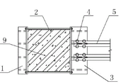
The elevation that Fig. 1 is the utility model high-strength bolt anchor ear bracket bracing means.
The right view that Fig. 2 is the utility model high-strength bolt anchor ear bracket bracing means.
The top view that Fig. 3 is the utility model high-strength bolt anchor ear bracket bracing means.
In figure: 1-stirrup beam, 2-high-strength bolt, 3-steel corbel, 4-bolt assembly, 5-steel joist, 6-rubber sheet gasket, 7-U shape steel plate, the former frame structural beam of 8-, the former frame construction post of 9-.
The specific embodiment
Below in conjunction with drawings and Examples, the utility model is described further.
As shown in Figure 1, Figure 2 and Figure 3, a kind of high-strength bolt anchor ear bracket bracing means, comprise former frame structural beam 8, former frame construction post 9 and steel corbel 3.
Former frame construction post 9 is provided with stirrup beam 1, is symmetrically arranged with on stirrup beam 1 and steel corbel 3 and is provided with 4 pairs of bolts hole, and bolt hole and high-strength bolt 2 are suitable.High-strength bolt 2 is provided with 4, and stirrup beam 1 is fixedly connected with by high-strength bolt 2 with steel corbel 3.Form anchor ear by stirrup beam 1, high-strength bolt 2 and steel corbel 3, be clamped in the appropriate location of former frame construction post 9.
Former frame structural beam 8 lower ends are provided with the power transmission assembly, the power transmission assembly comprises steel joist 5, rubber sheet gasket 6 and U-shaped steel plate 7, the antiarch that steel joist 5 is 1/1000, be provided with rubber sheet gasket 6 between steel joist 5 and U-shaped steel plate 7, the span of lower end U-shaped steel plate 7 that U-shaped steel plate 7 is located at former frame structural beam 8 is consistent with the width of former frame structural beam 8, the thickness of U-shaped steel plate 7 is 2mm, outward appearance for the protection of former concrete beam 8, the end face of steel joist 5 or steel corbel 3 is provided with bolt hole, bolt hole and bolt assembly 4 are suitable, steel joist 5 is fixedly connected with by bolt assembly 4 with the end face of steel corbel 3.
Teachings herein is example of the present utility model and explanation; but do not mean that the obtainable advantage of the utility model is so limited, may be to wherein one or more of the advantage that realizes in the simple transformation of structure and/or some embodiments all in the application's protection domain in every the utility model practice process.
Claims (8)
1. a high-strength bolt anchor ear bracket bracing means, comprise former frame structural beam (8), former frame construction post (9) and steel corbel (3), it is characterized in that: described former frame construction post (9) is provided with stirrup beam (1), described stirrup beam (1) is fixedly connected with by high-strength bolt (2) with steel corbel (3), described former frame structural beam (8) lower end is provided with the power transmission assembly, and described power transmission assembly is fixedly connected with by bolt assembly (4) with the end face of steel corbel (3).
2. high-strength bolt anchor ear bracket bracing means according to claim 1, it is characterized in that: described stirrup beam (1) or steel corbel (3) are provided with bolt hole, and described bolt hole and high-strength bolt (2) are suitable.
3. high-strength bolt anchor ear bracket bracing means according to claim 1 is characterized in that: described high-strength bolt (2) is provided with 3-6.
4. high-strength bolt anchor ear bracket bracing means according to claim 1, it is characterized in that: described power transmission assembly comprises steel joist (5), rubber sheet gasket (6) and U-shaped steel plate (7), described U-shaped steel plate (7) is located at the lower end of former frame structural beam (8), the span of described U-shaped steel plate (7) is consistent with the width of former frame structural beam (8), between described steel joist (5) and U-shaped steel plate (7), is provided with rubber sheet gasket (6).
5. high-strength bolt anchor ear bracket bracing means according to claim 4, is characterized in that: the antiarch that described steel joist (5) is 1/1000.
6. high-strength bolt anchor ear bracket bracing means according to claim 4, it is characterized in that: the end face of described steel joist (5) or steel corbel (3) is provided with bolt hole, and described bolt hole and bolt assembly (4) are suitable.
7. high-strength bolt anchor ear bracket bracing means according to claim 4 is characterized in that:
The thickness of U-shaped steel plate (7) is 2mm.
8. high-strength bolt anchor ear bracket bracing means according to claim 2 is characterized in that:
Bolt hole on described stirrup beam and steel corbel is symmetrical.
Priority Applications (1)
| Application Number | Priority Date | Filing Date | Title |
|---|---|---|---|
| CN2013204122460U CN203320979U (en) | 2013-07-11 | 2013-07-11 | Reinforcing device of high-strength bolt hoop bracket |
Applications Claiming Priority (1)
| Application Number | Priority Date | Filing Date | Title |
|---|---|---|---|
| CN2013204122460U CN203320979U (en) | 2013-07-11 | 2013-07-11 | Reinforcing device of high-strength bolt hoop bracket |
Publications (1)
| Publication Number | Publication Date |
|---|---|
| CN203320979U true CN203320979U (en) | 2013-12-04 |
Family
ID=49660343
Family Applications (1)
| Application Number | Title | Priority Date | Filing Date |
|---|---|---|---|
| CN2013204122460U Expired - Fee Related CN203320979U (en) | 2013-07-11 | 2013-07-11 | Reinforcing device of high-strength bolt hoop bracket |
Country Status (1)
| Country | Link |
|---|---|
| CN (1) | CN203320979U (en) |
Cited By (5)
| Publication number | Priority date | Publication date | Assignee | Title |
|---|---|---|---|---|
| CN106948478A (en) * | 2017-03-23 | 2017-07-14 | 上海建工五建集团有限公司 | PC structural columns, girder connection anchor ear corbel type precast beam supporting construction and method |
| CN107190999A (en) * | 2017-05-18 | 2017-09-22 | 北京交通大学 | A kind of multi-functional anchor ear of pin and preparation method thereof |
| CN107905552A (en) * | 2017-09-25 | 2018-04-13 | 上海建工七建集团有限公司 | A kind of superstructure construction auxiliary stand and method |
| CN108952207A (en) * | 2018-09-25 | 2018-12-07 | 中国化学工程第三建设有限公司 | A kind of layer reinforced structure and increasing layer method of steel building |
| CN113846578A (en) * | 2021-10-29 | 2021-12-28 | 广州市第二市政工程有限公司 | Support bent cap reinforced damaged bracket structure of cantilever bridge and construction method thereof |
-
2013
- 2013-07-11 CN CN2013204122460U patent/CN203320979U/en not_active Expired - Fee Related
Cited By (7)
| Publication number | Priority date | Publication date | Assignee | Title |
|---|---|---|---|---|
| CN106948478A (en) * | 2017-03-23 | 2017-07-14 | 上海建工五建集团有限公司 | PC structural columns, girder connection anchor ear corbel type precast beam supporting construction and method |
| CN107190999A (en) * | 2017-05-18 | 2017-09-22 | 北京交通大学 | A kind of multi-functional anchor ear of pin and preparation method thereof |
| CN107190999B (en) * | 2017-05-18 | 2019-04-05 | 北京交通大学 | A kind of multi-functional anchor ear of pin and preparation method thereof |
| CN107905552A (en) * | 2017-09-25 | 2018-04-13 | 上海建工七建集团有限公司 | A kind of superstructure construction auxiliary stand and method |
| CN108952207A (en) * | 2018-09-25 | 2018-12-07 | 中国化学工程第三建设有限公司 | A kind of layer reinforced structure and increasing layer method of steel building |
| CN108952207B (en) * | 2018-09-25 | 2023-09-19 | 中国化学工程第三建设有限公司 | Steel structure building storey adding structure and storey adding method |
| CN113846578A (en) * | 2021-10-29 | 2021-12-28 | 广州市第二市政工程有限公司 | Support bent cap reinforced damaged bracket structure of cantilever bridge and construction method thereof |
Similar Documents
| Publication | Publication Date | Title |
|---|---|---|
| CN203320979U (en) | Reinforcing device of high-strength bolt hoop bracket | |
| CN103924674A (en) | High-strength bolt shear key structure and constructing method thereof | |
| CN203021899U (en) | Quick-assembling template device for concrete ground construction | |
| CN105259020A (en) | Seismic performance test loading device for shear wall under combined action of pulling, bending and shearing | |
| CN104131630B (en) | Multi-tube lattice type buckling restrained brace | |
| CN204282544U (en) | A kind of joint reinforcing and energy consuming mechanism | |
| CN203201146U (en) | Spacers for column template reinforcement | |
| CN204081079U (en) | A kind of structure of open pore steel plate shear force | |
| CN203924364U (en) | The prestressing force assembling frame structure node syndeton of additional angle steel | |
| CN203924363U (en) | The syndeton of friction damper assembling frame node | |
| CN201883543U (en) | Hinged structure of steel girder and steel column | |
| CN202323717U (en) | Cantilever type pre-stress hoop and special tensioning device thereof | |
| CN103615069A (en) | Trussed steel rib concrete coupling beam | |
| CN202227586U (en) | Steel structure concrete combination beam | |
| CN205153145U (en) | Adopt precast concrete coincide floor of bolt and connection structure of H shaped steel roof beam | |
| CN103850434A (en) | Template capable of finishing construction of shear wall tension screw at one side | |
| CN202284359U (en) | Steel structure concrete support beam | |
| CN202466841U (en) | Through type connection node for connecting steel tube column and steel beam partition plate | |
| CN203939245U (en) | A kind of string girder tensioning frock | |
| CN204960324U (en) | Suspension type floor formwork support device | |
| CN204081120U (en) | Multi-tube lattice type buckling restrained brace | |
| CN202380645U (en) | Steel bar anchoring component with reinforced concrete structure | |
| CN201666004U (en) | Reinforcing body connected by using anchor bolts | |
| CN205296525U (en) | Lower hanging steel bar truss structure | |
| CN204804047U (en) | Shear force wall building structure connecting device |
Legal Events
| Date | Code | Title | Description |
|---|---|---|---|
| C14 | Grant of patent or utility model | ||
| GR01 | Patent grant | ||
| CF01 | Termination of patent right due to non-payment of annual fee |
Granted publication date: 20131204 Termination date: 20160711 |
|
| CF01 | Termination of patent right due to non-payment of annual fee |