CN203317681U - Integral embedded cavity mold - Google Patents
Integral embedded cavity mold Download PDFInfo
- Publication number
- CN203317681U CN203317681U CN2013203597265U CN201320359726U CN203317681U CN 203317681 U CN203317681 U CN 203317681U CN 2013203597265 U CN2013203597265 U CN 2013203597265U CN 201320359726 U CN201320359726 U CN 201320359726U CN 203317681 U CN203317681 U CN 203317681U
- Authority
- CN
- China
- Prior art keywords
- module
- type
- cavity
- core
- upper bolster
- Prior art date
- Legal status (The legal status is an assumption and is not a legal conclusion. Google has not performed a legal analysis and makes no representation as to the accuracy of the status listed.)
- Expired - Fee Related
Links
Images
Abstract
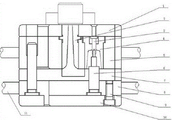
The utility model discloses an integral embedded cavity mold, comprising an upper die holder module, sprue bush modules, a first mold core module, a cavity module, an upper template module, a second mold core module, a stripper plate module, a fixed plate module, a fixed module, a lower die holder module and a handle module, wherein the upper die holder module is orderly provided with the upper template module, the stripper plate module, the fixed plate module and the lower die holder module from top to bottom; the sprue bush module is arranged inside the middle of the upper die holder module and the stripper plate module; the first mold core module, the cavity module and the second mold core module are arranged at one side between the upper die holder module and the lower die holder module; one side of the first mold core module is connected to the cavity module; one side of the cavity module is connected with the second mold core module; the handle module is arranged on the upper template module and the fixed plate module; the fixed plate module and the lower die holder module are fixedly connected through the fixed module.
Description
Technical field
The utility model relates to technical field of mold, is specifically related to a kind of integral embedded type type cavity mould.
Background technology
At present, in manufacturing enterprise, generally utilize adapter sleeve to transmit mould and produced, its high efficiency, easy to operate.
But existing adapter sleeve transmission Design of Dies is unreasonable, production efficiency is low and product percent of pass that produce is low, thereby has indirectly increased the production infusion of financial resources cost of enterprise, and its irrational design simultaneously also directly causes the shortening in its service life.
Therefore, based on the problems referred to above, the utility model provides a kind of integral embedded type type cavity mould.
The utility model content
The utility model purpose: the purpose of this utility model is that a kind of reasonable in design, simple in structure, mould that punching precision is higher will be provided, and solves the deficiencies in the prior art, and the production cost of enhancing productivity, reduce enterprise drops into.
Technical scheme: a kind of integral embedded type type cavity mould comprises upper bolster module, sprue bush module, the first core module, die cavity module, cope match-plate pattern module, Second-Type core module, push piece plate module, fixed head module, stuck-module, die shoe module and handle module; Described upper bolster module sets gradually cope match-plate pattern module, push piece plate module, fixed head module and die shoe module from top to bottom; Described sprue bush module is arranged on upper bolster module and push piece plate module inside middle; Described the first core module, die cavity module and Second-Type core module are arranged on a side between upper bolster module and die shoe module, and wherein the first core module one side connects the die cavity module, and die cavity module one side connects the Second-Type core module; Described handle module is arranged on cope match-plate pattern module and fixed head module; Described fixed head module, die shoe module are fixedly connected with by stuck-module.
Preferred described upper bolster module, sprue bush module, the first core module, die cavity module, cope match-plate pattern module, Second-Type core module, push piece plate module, stuck-module are connected by screw rod with handle module.
Preferred described stuck-module screw number is 4-10.
Preferred described handle module adopts metal-made to obtain.
Compared with prior art, the beneficial effects of the utility model are:
Adopt a kind of integral embedded type type cavity mould of the present utility model, this device project organization rationally, save material, the product accuracy of manufacture is higher, improve service life and the production efficiency of mould, improved the qualification rate of manufacturing product, reduced the input of business capital cost; The utility model is simple to operate simultaneously, easily promotes.
The accompanying drawing explanation
The structural representation that Fig. 1 is the utility model embodiment;
Wherein, in figure, sequence number is as follows: 1-upper bolster module, 2-sprue bush module, 3-the first core module, 4-die cavity module, 5-cope match-plate pattern module, 6-Second-Type core module, 7-push piece plate module, 8-fixed head module, 9-stuck-module, 10-die shoe module, 11-handle module.
The specific embodiment
Below in conjunction with specific embodiment, a kind of integral embedded type type cavity mould described in the utility model is elaborated:
A kind of integral embedded type type cavity mould as shown in Figure 1, comprise upper bolster module 1, sprue bush module 2, the first core module 3, die cavity module 4, cope match-plate pattern module 5, Second-Type core module 6, push piece plate module 7, fixed head module 8, stuck-module 9, die shoe module 10 and handle module 11; Upper bolster module 1 sets gradually cope match-plate pattern module 5, push piece plate module 7, fixed head module 8 and die shoe module 10 from top to bottom; Sprue bush module 2 is arranged on upper bolster module 1 and push piece plate module 7 inside middle; The first core module 3, die cavity module 4 and Second-Type core module 6 are arranged on a side between upper bolster module 1 and die shoe module 10, and wherein the first core module 3 one sides connect die cavity module 4, and die cavity module 4 one sides connect Second-Type core module 6; Handle module 11 is arranged on cope match-plate pattern module 5 and fixed head module 8; Fixed head module 8, die shoe module 10 are fixedly connected with by stuck-module 9.
Preferred upper bolster module 1, sprue bush module 2, the first core module 3, die cavity module 4, cope match-plate pattern module 5, Second-Type core module 6, push piece plate module 7, stuck-module 9 are connected by screw rod with handle module 11.
Preferred stuck-module 9 screw numbers are 4-10.
Preferred handle module 11 adopts metal-made to obtain.
The above is only preferred embodiment of the present utility model; it should be pointed out that for those skilled in the art, under the prerequisite that does not break away from the utility model principle; can also make some improvement, these improvement also should be considered as protection domain of the present utility model.
Claims (4)
1. an integral embedded type type cavity mould, is characterized in that: comprise upper bolster module (1), sprue bush module (2), the first core module (3), die cavity module (4), cope match-plate pattern module (5), Second-Type core module (6), push piece plate module (7), fixed head module (8), stuck-module (9), die shoe module (10) and handle module (11); Described upper bolster module (1) sets gradually cope match-plate pattern module (5), push piece plate module (7), fixed head module (8) and die shoe module (10) from top to bottom; Described sprue bush module (2) is arranged on upper bolster module (1) and push piece plate module (7) inside middle; Described the first core module (3), die cavity module (4) and Second-Type core module (6) are arranged on a side between upper bolster module (1) and die shoe module (10), wherein the first core module (3) one sides connect die cavity module (4), and die cavity module (4) one sides connect Second-Type core module (6); Described handle module (11) is arranged on cope match-plate pattern module (5) and fixed head module (8); Described fixed head module (8), die shoe module (10) are fixedly connected with by stuck-module (9).
2. a kind of integral embedded type type cavity mould according to claim 1, it is characterized in that: described upper bolster module (1), sprue bush module (2), the first core module (3), die cavity module (4), cope match-plate pattern module (5), Second-Type core module (6), push piece plate module (7), stuck-module (9) are connected by screw rod with handle module (11).
3. a kind of integral embedded type type cavity mould according to claim 1 is characterized in that: described stuck-module (9) screw number is 4-10.
4. a kind of integral embedded type type cavity mould according to claim 1 is characterized in that: described handle module (11) adopts metal-made to obtain.
Priority Applications (1)
| Application Number | Priority Date | Filing Date | Title |
|---|---|---|---|
| CN2013203597265U CN203317681U (en) | 2013-06-23 | 2013-06-23 | Integral embedded cavity mold |
Applications Claiming Priority (1)
| Application Number | Priority Date | Filing Date | Title |
|---|---|---|---|
| CN2013203597265U CN203317681U (en) | 2013-06-23 | 2013-06-23 | Integral embedded cavity mold |
Publications (1)
| Publication Number | Publication Date |
|---|---|
| CN203317681U true CN203317681U (en) | 2013-12-04 |
Family
ID=49657071
Family Applications (1)
| Application Number | Title | Priority Date | Filing Date |
|---|---|---|---|
| CN2013203597265U Expired - Fee Related CN203317681U (en) | 2013-06-23 | 2013-06-23 | Integral embedded cavity mold |
Country Status (1)
| Country | Link |
|---|---|
| CN (1) | CN203317681U (en) |
Cited By (1)
| Publication number | Priority date | Publication date | Assignee | Title |
|---|---|---|---|---|
| CN103317752A (en) * | 2013-06-23 | 2013-09-25 | 苏州腾行精密模具有限公司 | Integrally embedded type cavity mould |
-
2013
- 2013-06-23 CN CN2013203597265U patent/CN203317681U/en not_active Expired - Fee Related
Cited By (1)
| Publication number | Priority date | Publication date | Assignee | Title |
|---|---|---|---|---|
| CN103317752A (en) * | 2013-06-23 | 2013-09-25 | 苏州腾行精密模具有限公司 | Integrally embedded type cavity mould |
Similar Documents
| Publication | Publication Date | Title |
|---|---|---|
| CN203711612U (en) | Die for forming automobile plug | |
| CN203317681U (en) | Integral embedded cavity mold | |
| CN203330265U (en) | Continuous stamping punching die | |
| CN203304412U (en) | Movable material cavity die | |
| CN203304415U (en) | Manual semi-positive compression ring die | |
| CN203304414U (en) | Manual positive double-layered circular sleeve die-pressing die | |
| CN203317680U (en) | Injection molding mould of pressing ring | |
| CN203371716U (en) | Manual semi-positive mold | |
| CN203304413U (en) | Suspension-type trimming punching mould | |
| CN203737825U (en) | Automotive plug grinding tool | |
| CN203317674U (en) | Side gate multilayer combined die | |
| CN203317605U (en) | External thread cavity molding mould | |
| CN203316563U (en) | Trimming die provided with sliding blocks on four sides | |
| CN203401675U (en) | Novel aluminum alloy mold | |
| CN203409960U (en) | Screw type injection mold | |
| CN204672788U (en) | The blanking die that a kind of raw material availability is high | |
| CN203401681U (en) | Improved nozzle injection mould | |
| CN103317649A (en) | Manual semipositive mould | |
| CN203317678U (en) | Nozzle injection mould | |
| CN203390059U (en) | Improved stamping die | |
| CN103317752A (en) | Integrally embedded type cavity mould | |
| CN203401684U (en) | Improved screw rod injection mold | |
| CN203401679U (en) | Screw rod injection mold | |
| CN203317682U (en) | Four-face rotary-cut injection mould | |
| CN203061652U (en) | Floating type up-and-down hydraulic punching mechanism |
Legal Events
| Date | Code | Title | Description |
|---|---|---|---|
| C14 | Grant of patent or utility model | ||
| GR01 | Patent grant | ||
| CF01 | Termination of patent right due to non-payment of annual fee |
Granted publication date: 20131204 Termination date: 20140623 |
|
| EXPY | Termination of patent right or utility model |