CN203308181U - Assisting handle and refrigerator - Google Patents
Assisting handle and refrigerator Download PDFInfo
- Publication number
- CN203308181U CN203308181U CN2013201317077U CN201320131707U CN203308181U CN 203308181 U CN203308181 U CN 203308181U CN 2013201317077 U CN2013201317077 U CN 2013201317077U CN 201320131707 U CN201320131707 U CN 201320131707U CN 203308181 U CN203308181 U CN 203308181U
- Authority
- CN
- China
- Prior art keywords
- rotary part
- refrigerator
- catch base
- push pedal
- parts
- Prior art date
- Legal status (The legal status is an assumption and is not a legal conclusion. Google has not performed a legal analysis and makes no representation as to the accuracy of the status listed.)
- Expired - Fee Related
Links
Images


Landscapes
- Refrigerator Housings (AREA)
Abstract
The utility model belongs to the technical field of electrical equipment and particularly relates to an assisting handle and a refrigerator provided with the assisting handle. The assisting handle comprises a pull rod arranged on a door body of the refrigerator and one or two assisting mechanisms. Each assisting mechanism comprises a rotary part and a shoving part, wherein the shoving part is arranged on the opening-closing side of the door body of the refrigerator and can slide to abut against the front end of the body of the refrigerator, one end of the rotary part is fixed on the pull rod, and the other end of the rotary part is in contact with the shoving part and can push the shoving part to slide. According to the assisting handle, the assisting mechanisms are adopted, little force is applied to the pull rod by a user, the shoving parts are pushed by the rotary parts, one ends of the shoving parts slide to abut against the body of the refrigerator so that transmission of the force can be achieved, and then the door body of the refrigerator can be opened with little force.
Description
Technical field
The utility model belongs to the technical field of electric equipment, particularly a kind of boosting handle and have the refrigerator of this boosting handle.
Background technology
Along with the raising of quality of the life, people become greatly gradually to the storage space demand of refrigerator in daily life, make large volume refrigerator product enjoy and pursue.When the refrigerator volume increased, volume was also increasing, make refrigerator door also corresponding uprising broaden.Along with refrigerator product enriching at aspects such as functions, bar desk, water dispenser, on door, the fashion elements such as automatic ice-making also starts to apply on the door body of large volume refrigerator, when having met people and more use needs, a door body weight has also increased the weight of a lot, and people are when opening refrigerator doors, the power that needs to use also becomes much larger, uses very inconvenient.Existing refrigerator is fixed handle mostly, when refrigerator doors is opened, requires great effort very much, particularly for old man and weakling.
Therefore, need to find a kind of boosting handle, the difficulty of opening to reduce refrigerator doors.
The utility model content
Problem to be solved in the utility model is to provide a kind of boosting handle for the deficiencies in the prior art, this boosting handle plays booster action to opening refrigerator doors, reduced the pulling force that refrigerator open needs, making to open the door becomes simple, has solved open the door a difficult difficult problem of old man and weakling.
The utility model also provides a kind of refrigerator that is provided with above-mentioned boosting handle.
For solving the problems of the technologies described above, technical solutions of the utility model are:
The utility model provides a kind of boosting handle, it comprises pull bar and one or two servomechanism of being located on refrigerator door, described servomechanism comprises rotary part and pushes parts open, the described parts of pushing open are located at the folding side of refrigerator door and slidably extremely with the refrigerator body front end, offset, described rotary part one end is fixed on pull bar, and the other end slides with pushing that parts contact open and can promote to push open parts.By rotary part, promote to push open parts, thereby prop up the transmission of refrigerator body realizable force, realize opening refrigerator door by less power.
Further, the described parts of pushing open comprise catch base and the push pedal be slidably matched, described catch base is fixed on refrigerator door, which is provided with sliding rail groove, described push pedal and catch base contact surface are provided with the slide rail boss with the sliding rail groove coupling, the slide rail boss of push pedal slips into the sliding rail groove of catch base, can guarantee that push pedal does straight reciprocating motion along the sliding rail groove of catch base; One end of push pedal is connected with rotary part and at catch base, slides under the promotion of rotary part, and its other end stretches out with the refrigerator body front end and offsets.Push parts open and adopt catch base and the push pedal be slidably matched, rotary part is to the direction of the active force of push pedal along the push pedal glide direction, and push pedal can not be subject to making the power of its buckling deformation like this.
Further, described rotary part comprises, lower plate, form hollow structure, rotary part upper, on lower plate, correspondence is provided with axis hole, described catch base mates and embeds in this hollow structure near an end and this hollow structure of rotary part, described built-in end comprises the end plate up and down that forms a space, the corresponding axis hole that is provided with of axis hole of upper and lower end plate and hollow structure, in the space that the end plate up and down of built-in end forms, be provided with spring, axle passes the axis hole of rotary part upper plate successively, the axis hole of catch base built-in end upper head plate, spring, the axis hole of catch base built-in end bottom plate and the axis hole of rotary part lower plate, each parts are linked together, having assembled rear rotary part pivots, spring backs down after refrigerator doors is loosed one's grip boosting handle rotary part is automatically reset.
Further, the link of described push pedal and rotary part is provided with button bit, and rotary part is provided with the T shape structure that can hook button bit, and push pedal is resetted with rotary part.The button bit of the link part of push pedal and rotary part is embedded in the set T shape structure of rotary part, guarantees that push pedal can perk along the refrigerator vertical direction.
Further, the end that offsets of described push pedal 8 and refrigerator body sidewall is provided with in position, Wei, hole, hole and is provided with the flexible material that does not abrade refrigerator body.This flexible material 7 is preferably elastomeric material, the rubber elastically deformable, thus the protection refrigerator body is injury-free.
Further, described pull bar is the column pull bar, and described rotary part and pull bar contact surface are cambered surface, and its radian is identical with the cambered surface radian of pull bar, like this gapless after the assembling; By screw, rotary part and pull bar are fixed together, can meet the client and use.
Above-mentioned boosting handle also comprises outer cover, and described outer cover is connected to the external surface of catch base.
Above-mentioned boosting handle also comprises bonnet, and described bonnet is connected to the external surface of rotary part.
Wherein, outer cover and bonnet are appearance part, can cover internal part, play beauty function.
The utility model also provides a kind of refrigerator, comprises refrigerator body, refrigerator door and is located at the handle on refrigerator door, and described handle is above-mentioned boosting handle.
Compared with prior art, the utlity model has following beneficial effect:
The utility model boosting handle adopts servomechanism, and the user applies less power on pull bar, promotes to push open parts by rotary part, pushes parts one end open and slides into the transmission that props up the refrigerator body realizable force, thereby realize opening refrigerator door by less power.After refrigerator door was opened, the power be applied on pull bar was cancelled, and the back-moving spring of rotary part inside resets, and drive is simultaneously pushed parts open and is retracted into reset condition, the refrigerator body of damaging while avoiding the refrigerator door quick closedown.The utility model adopts the refrigerator of this boosting handle, and the user only need just can complete the action of opening the door by less power, makes the more convenient and hommization of opening door operation.The utility model is practical, is widely used.
The accompanying drawing explanation
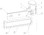
Fig. 1 is the blast of the utility model embodiment catch and scheme of installation;
Fig. 2 is the utility model embodiment catch assembling schematic diagram;
Fig. 3 is the assembling schematic diagram of the utility model embodiment rotary part, catch base and push pedal;
Fig. 4 is the utility model embodiment rotary part and push pedal assembling schematic diagram.
In figure, pull bar 1 rotary part 2 spring 3 axle 4 catch base 5 first screw 6 flexible material 7 push pedal 8 outer cover 9 second screw 10 bonnet 11 refrigerator door 12 refrigerator body 13 T shape structure 21 sliding rail groove 51 slide rail boss 81 button bits 82.
The specific embodiment
Below in conjunction with embodiment and accompanying drawing, the utility model is described in detail.
The utility model discloses a kind of boosting handle, comprises pull bar 1 and the servomechanism be located on refrigerator door 12, pull bar two ends can be equipped with two servomechanisms or an end for fixing without rushing board mechanism, the other end is equipped with servomechanism.
In Fig. 1, Fig. 2, servomechanism comprises rotary part 2 and pushes parts open, push that parts are located at the folding side of refrigerator door 12 and slidably to the refrigerator body front end, offseting, rotary part 2 one ends are fixed on pull bar 1 open, the other end with push that parts contact and can promote to push open the parts slip open.Push parts open and comprise catch base 5 and the push pedal 8 be slidably matched, catch base 5 is fixed on refrigerator door 12 sides, see Fig. 3, catch base 5 is provided with sliding rail groove 51, push pedal 8 is provided with catch base 5 contact surfaces the slide rail boss 81 mated with sliding rail groove 51, the slide rail boss 81 of push pedal 8 slips into the sliding rail groove 51 of catch base 5, can guarantee that push pedal 8 does straight reciprocating motion along the sliding rail groove 51 of catch base 5, realizes sliding each other between push pedal 8 and catch base 5.
Fig. 2, an end of push pedal 8 are connected with rotary part 2 and on catch base 5, are sliding under the promotion of rotary part 2, and the other end stretches out with refrigerator body 13 front end side wall and offsets.Push parts open and adopt catch base 5 and the push pedal 8 be slidably matched, the direction of the active force of 2 pairs of push pedals 8 of rotary part is along push pedal 8 glide directions, and push pedal 8 can not be subject to making the power of its buckling deformation like this.
In addition, rotary part 2 comprises, lower plate, on, lower plate forms hollow structure, and correspondence is provided with axis hole, catch base 5 mates and embeds in this hollow structure near an end and this hollow structure of rotary part 2, this described built-in end comprises the end plate up and down that forms a space, the corresponding axis hole that is provided with of axis hole of upper and lower end plate and hollow structure, in the space that the end plate up and down of this built-in end forms, be provided with spring 3, axle 4 passes the axis hole of rotary part 2 upper plates successively, the axis hole of catch base 5 built-in end upper head plates, spring 3, the axis hole of the axis hole of catch base 5 built-in end bottom plates and rotary part 2 lower plates, each parts are linked together, and realize rotating.Spring 3 can reset pull bar 1 band rotary part 2 when axle 4 motion like this.
Fig. 3, push pedal 8 is provided with button bit 82 with the link of rotary part 2, and rotary part 2 is provided with the T shape structure 21 that can hook button bit 82.By T shape structure 21, hook button bit 82, rotary part 2 and push pedal 8 are linked together.
Then, catch base 5 tightens together with refrigerator door 12 by the first screw 6.See Fig. 1 and Fig. 2.
In Fig. 1 and Fig. 4, pull bar 1 is the column pull bar, and rotary part 2 is cambered surface with pull bar 1 contact surface, and its radian is identical with the cambered surface radian of pull bar 1, and rotary part 2 is provided with bolt hole, adopts the second screw 10 to pass bolt hole rotary part 2 is fixed on pull bar 1.
By above-mentioned structure, the external force driven rotary parts 2 on being applied to pull bar 1 are when axle 4 motion, but the T shape structure 21 push-and-pull push pedals 8 of rotary part 2 ends are slided push pedal 8 on catch base 5, realize stretching motion.When push pedal 8 is stretched out, contact and offset with refrigerator body 13, can open refrigerator door 12.When releasing lever 1, external force is cancelled, and the spring 3 that is embedded in catch base 5 built-in ends and rotary part 2 inside resets rotary part 2, and while rotary part 2 hooks push pedal 8 by its T shape structure 21 resets push pedal 8 retractions.
In addition, stretch out and with refrigerator body 13, contact while offseting the infringement of refrigerator body 13 in order to eliminate push pedal 8, be provided with in position, Wei, hole, hole and be provided with the flexible material that does not abrade refrigerator body in the end that push pedal 8 and refrigerator body 13 sidewalls offset.This flexible material 7 is preferably elastomeric material, the rubber elastically deformable, thus protection refrigerator body 13 is injury-free.See Fig. 1 and Fig. 2.
In addition, in order to cover the internal part of boosting handle, reach boosting handle specious succinct, the utility model boosting handle also is provided with outer cover 9 and bonnet 11, wherein bonnet 11 inboards respectively have a buckle up and down, are connected in the set square hole of the upper and lower plate of rotary part 2; Outer cover 9 inboards respectively have a buckle up and down, are connected on the upper lower convex platform of catch base 5, and there is a buckle outer cover 9 rear ends, are connected in the set square hole in catch base 5 rear ends.See Fig. 1 and Fig. 2.
The utility model also discloses a kind of refrigerator, comprises refrigerator body, refrigerator door and is located at the handle on refrigerator door, shakes hands as above-mentioned boosting handle.
Above embodiment only, be used to the technical solution of the utility model is described, is not intended to limit; Although with reference to preferred embodiment, the utility model is had been described in detail; those of ordinary skill in the field are to be understood that; still can modify or the part technical characterictic is equal to replacement the specific embodiment of the present utility model; and not breaking away from the spirit of technical solutions of the utility model, it all should be encompassed in the middle of the technical scheme scope that the utility model asks for protection.
Claims (10)
1. boosting handle, comprise the pull bar of being located on refrigerator door, it is characterized in that: also comprise one or two servomechanism, described servomechanism comprises rotary part and pushes parts open, the described parts of pushing open are located at the folding side of refrigerator door and slidably extremely with the refrigerator body front end, offset, described rotary part one end is fixed on pull bar, and the other end slides with pushing that parts contact open and can promote to push open parts.
2. boosting handle according to claim 1, it is characterized in that: the described parts of pushing open comprise catch base and the push pedal be slidably matched, described catch base is fixed on refrigerator door, which is provided with sliding rail groove, described push pedal and catch base contact surface are provided with the slide rail boss with the sliding rail groove coupling, and the slide rail boss of push pedal slips into the sliding rail groove of catch base; One end of push pedal is connected with rotary part and on catch base, slides under the promotion of rotary part, and its other end stretches out afterwards and the refrigerator body front end offsets.
3. boosting handle according to claim 2, it is characterized in that: described rotary part comprises, lower plate, form hollow structure, rotary part upper, on lower plate, correspondence is provided with axis hole, described catch base mates and embeds in this hollow structure near an end and this hollow structure of rotary part, described built-in end comprises the end plate up and down that forms a space, the corresponding axis hole that is provided with of axis hole of upper and lower end plate and hollow structure, in the space that the end plate up and down of built-in end forms, be provided with spring, axle passes the axis hole of rotary part upper plate successively, the axis hole of catch base built-in end upper head plate, spring, the axis hole of catch base built-in end bottom plate and the axis hole of rotary part lower plate, each parts are linked together.
4. boosting handle according to claim 3, it is characterized in that: the link of described push pedal and rotary part is provided with button bit, and rotary part is provided with the T shape structure that can hook button bit.
5. boosting handle according to claim 2, the end that described push pedal and refrigerator body sidewall offset is provided with the flexible material that does not abrade refrigerator body.
6. boosting handle according to claim 5, it is characterized in that: described flexible material is rubber.
7. according to the described boosting handle of claim 1 to 6 any one, it is characterized in that: described pull bar is the column pull bar, and described rotary part and pull bar contact surface are cambered surface, and its radian is identical with the cambered surface radian of pull bar.
8. boosting handle according to claim 7, it is characterized in that: also comprise outer cover, described outer cover is connected to the external surface of catch base.
9. boosting handle according to claim 7, it is characterized in that: also comprise bonnet, described bonnet is connected to the external surface of rotary part.
10. a refrigerator, comprise refrigerator body, refrigerator door and be located at the handle on refrigerator door, it is characterized in that: described handle is the described boosting handle of claim 1 to 9 any one.
Priority Applications (1)
| Application Number | Priority Date | Filing Date | Title |
|---|---|---|---|
| CN2013201317077U CN203308181U (en) | 2013-03-21 | 2013-03-21 | Assisting handle and refrigerator |
Applications Claiming Priority (1)
| Application Number | Priority Date | Filing Date | Title |
|---|---|---|---|
| CN2013201317077U CN203308181U (en) | 2013-03-21 | 2013-03-21 | Assisting handle and refrigerator |
Publications (1)
| Publication Number | Publication Date |
|---|---|
| CN203308181U true CN203308181U (en) | 2013-11-27 |
Family
ID=49614400
Family Applications (1)
| Application Number | Title | Priority Date | Filing Date |
|---|---|---|---|
| CN2013201317077U Expired - Fee Related CN203308181U (en) | 2013-03-21 | 2013-03-21 | Assisting handle and refrigerator |
Country Status (1)
| Country | Link |
|---|---|
| CN (1) | CN203308181U (en) |
Cited By (5)
| Publication number | Priority date | Publication date | Assignee | Title |
|---|---|---|---|---|
| CN103184811A (en) * | 2013-03-21 | 2013-07-03 | 海信容声(广东)冰箱有限公司 | Power-assisted handle and refrigerator |
| US20150275545A1 (en) * | 2014-03-28 | 2015-10-01 | Samsung Electronics Co., Ltd. | Door handle and refrigerator having the same |
| CN105486013A (en) * | 2015-08-31 | 2016-04-13 | 合肥华凌股份有限公司 | Assisting handle structure and refrigerator |
| CN110984800A (en) * | 2019-12-16 | 2020-04-10 | 北京建磊国际装饰工程股份有限公司 | Escape door |
| US12078406B2 (en) * | 2021-01-07 | 2024-09-03 | Lg Electronics Inc. | Refrigerator |
-
2013
- 2013-03-21 CN CN2013201317077U patent/CN203308181U/en not_active Expired - Fee Related
Cited By (8)
| Publication number | Priority date | Publication date | Assignee | Title |
|---|---|---|---|---|
| CN103184811A (en) * | 2013-03-21 | 2013-07-03 | 海信容声(广东)冰箱有限公司 | Power-assisted handle and refrigerator |
| CN103184811B (en) * | 2013-03-21 | 2016-05-25 | 海信容声(广东)冰箱有限公司 | A kind of boosting handle and refrigerator |
| US20150275545A1 (en) * | 2014-03-28 | 2015-10-01 | Samsung Electronics Co., Ltd. | Door handle and refrigerator having the same |
| CN105486013A (en) * | 2015-08-31 | 2016-04-13 | 合肥华凌股份有限公司 | Assisting handle structure and refrigerator |
| CN105486013B (en) * | 2015-08-31 | 2018-11-30 | 合肥华凌股份有限公司 | A kind of power-assisted handle structure and refrigerator |
| CN110984800A (en) * | 2019-12-16 | 2020-04-10 | 北京建磊国际装饰工程股份有限公司 | Escape door |
| CN110984800B (en) * | 2019-12-16 | 2021-07-06 | 北京建磊国际装饰工程股份有限公司 | Escape door |
| US12078406B2 (en) * | 2021-01-07 | 2024-09-03 | Lg Electronics Inc. | Refrigerator |
Similar Documents
| Publication | Publication Date | Title |
|---|---|---|
| CN203308181U (en) | Assisting handle and refrigerator | |
| US11761240B2 (en) | Safety lock device | |
| CN109538022A (en) | A kind of automatic locking unlocking and can instead lock tongue smart lock | |
| CN202083169U (en) | Hidden handle on refrigerator door body | |
| CN203171460U (en) | Telescopic pliers | |
| CN201718131U (en) | Remote controller holder and electronic device | |
| CN103479087A (en) | Shoe cabinet capable of automatically helping people to take off shoes | |
| CN205277028U (en) | Push -and -pull safety lock | |
| CN103184811B (en) | A kind of boosting handle and refrigerator | |
| CN204555029U (en) | Dehumidifier | |
| CN205591663U (en) | Automatic slider of intelligence lock | |
| CN202698247U (en) | Turnover device for computer desk | |
| CN201386456Y (en) | Bidirectional door opening mechanism of tank body | |
| CN203462828U (en) | Boosting handle of refrigerator drawer door | |
| CN206585134U (en) | Insert on a kind of ground for being easily installed functor | |
| CN206407052U (en) | A kind of folding handles structure of Segway Human Transporter | |
| CN109610952A (en) | A kind of latch bolt structure and the lockset with the structure | |
| CN110377122B (en) | Lever type labor-saving handle and using method thereof | |
| CN205156241U (en) | Dehumidifier and touch switch structure thereof | |
| CN211138889U (en) | Mechanical flower | |
| CN211647636U (en) | Sliding door lock | |
| CN201850843U (en) | Power-assisted door handle assembly and electrical equipment | |
| CN208915295U (en) | Facilitate access for the electric vehicle of lift car | |
| CN202151158U (en) | Moving and positioning mechanism for umbrella handle part of suspending umbrella | |
| CN217241107U (en) | Lifting structure and equipment |
Legal Events
| Date | Code | Title | Description |
|---|---|---|---|
| C14 | Grant of patent or utility model | ||
| GR01 | Patent grant | ||
| CF01 | Termination of patent right due to non-payment of annual fee | ||
| CF01 | Termination of patent right due to non-payment of annual fee |
Granted publication date: 20131127 Termination date: 20190321 |