CN203306568U - Jacking working table - Google Patents
Jacking working table Download PDFInfo
- Publication number
- CN203306568U CN203306568U CN2013203010190U CN201320301019U CN203306568U CN 203306568 U CN203306568 U CN 203306568U CN 2013203010190 U CN2013203010190 U CN 2013203010190U CN 201320301019 U CN201320301019 U CN 201320301019U CN 203306568 U CN203306568 U CN 203306568U
- Authority
- CN
- China
- Prior art keywords
- antifriction
- rolling bearing
- frame
- driving device
- drum
- Prior art date
- Legal status (The legal status is an assumption and is not a legal conclusion. Google has not performed a legal analysis and makes no representation as to the accuracy of the status listed.)
- Expired - Fee Related
Links
Images

Landscapes
- Lift-Guide Devices, And Elevator Ropes And Cables (AREA)
Abstract
The utility model provides a jacking working table which is used in a production line. The jacking working table comprises a rack. A spiral lifter is fixed on the rack. The spiral lifter comprises a threaded rod. A roller type transmission device is fixedly connected to the top end of the threaded rod. Two sets of scissor-shaped supporting bases which are hinged to a same rotary shaft are arranged between the roller type transmission device and the rack. The spiral lifter is retracted or jacked, therefore, the roller type transmission device drops or rises, adjustment on the spatial height of a product is further achieved, a worker can conveniently and comfortably carry out assembly operation on the product, and the work efficiency is improved.
Description
Technical field
The utility model relates to a kind of mechanical equipment, the jacking working platform particularly used on a kind of conveyor line.
Background technology
Bench board on existing domestic conveyor line is arranged on a fixing level height mostly, can't be according to the height of the specification size adjustment work top of product, as the workman when producing assembling small dimension product, need to squat down or bend over just can operate, and, when the large specification product of assembling, need to just can operate the product top by auxiliary device, because some product specification size differs very greatly different, so labor strength is very large, inefficiency.
The utility model content
The utility model provides matching used jacking working platform on a kind of conveyor line, and purpose is to solve the prior art problem, and a kind of jacking working platform that can improve workman's work efficiency is provided.
The utility model technical scheme adopted of dealing with problems is:
Jacking working platform, have frame, on frame, be fixed with a helical riser, helical riser comprises a screw rod, screw tip is connected with the drum-type driving device, between described drum-type driving device and frame, is provided with two groups and is articulated in same scissor supporting seat in rotating shaft.
Described every group of scissor supporting seat forms by a band steel and No. two band steel, a band steel and No. two band steel cross-articulation are in a rotating shaft, one end of a band steel is hinged with an antifriction-bearing box, the other end is hinged with rolling bearing units, No. one antifriction-bearing box is arranged on the frame end face, No. one rolling bearing units are fixed on drum-type driving device bottom surface, one end of No. two band steels is hinged with No. two antifriction-bearing boxs, the other end is hinged with No. two rolling bearing units, No. two antifriction-bearing box is arranged on drum-type driving device bottom surface, No. two rolling bearing units are fixed on the frame end face, No. two antifriction-bearing boxs be positioned at an antifriction-bearing box directly over, No. two rolling bearing units be positioned at rolling bearing units under.
The beneficial effects of the utility model:
The workman is according to above the drum-type driving device, carrying the product specification size of coming, starting helical riser retracts or jacking, thereby the drum-type driving device is descended or rise, and then the operational space height of product is regulated in realization, make the workman to product, carry out assembly manipulation in Energy and comfort ground, improved work efficiency.
The accompanying drawing explanation
Fig. 1 is the utility model jacking state front view;
Fig. 2 is the utility model jacking state right elevation;
Fig. 3 is the utility model decline state right elevation.
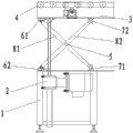
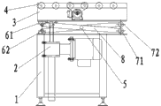
In figure: 1. frame, 2. helical riser, 3. drum-type driving device, 4. cylinder, 5. rotating shaft, No. 61. rolling bearing units, 62. No. two rolling bearing units, No. 71. antifriction-bearing boxs, 72. No. two antifriction-bearing boxs, No. 81. band steels, 82. No. two band steels.
The specific embodiment
The utility model is described in further detail below in conjunction with the drawings and specific embodiments.
As Fig. 1, Fig. 2, shown in Figure 3, the utility model is jacking working platform, has a frame 1, frame 1 is comprised of aluminum alloy frame and a plane steel plate, on frame 1, be fixed with a helical riser 2, helical riser 2 comprises a screw rod, screw tip is connected with drum-type driving device 3, this driving device is comprised of the several cylinders 4 that arrange in himself framework, cylinder 4 is by motor, belts etc. drive and form a roller conveyor line with conveying products, between described drum-type driving device 3 and frame 1, be provided with two groups and be articulated in same scissor supporting seat in rotating shaft 5, described every group of scissor supporting seat forms by a band steel 81 and No. two band steels 82, a band steel 81 and No. two band steel 82 cross-articulation are in same rotating shaft 5, one end of a band steel 81 is hinged with an antifriction-bearing box 71, the other end is hinged with rolling bearing units 61, No. one antifriction-bearing box 71 is arranged on frame 1 end face, No. one rolling bearing units 61 are fixed on drum-type driving device bottom surface, one end of No. two band steels 82 is hinged with No. two antifriction-bearing boxs 72, the other end is hinged with No. two rolling bearing units 62, No. two antifriction-bearing box 72 is arranged on drum-type driving device bottom surface, No. two rolling bearing units 62 are fixed on the frame end face, No. two antifriction-bearing boxs 72 be positioned at an antifriction-bearing box 71 directly over, No. two rolling bearing units 62 be positioned at rolling bearing units 61 under.
During work, after drum-type driving device 3 puts the product conveying in place, the workman is according to product specification size and technological requirement, starting helical riser 2 retracts or jacking, thereby make drum-type driving device 3 descend or rise, and then realize regulating the operational space height of product, make the workman to product, carry out assembly manipulation in Energy and comfort ground, complete after assembling and again start helical riser and drum-type driving device 3 is descended or rise, and start cylinder product is delivered to next station.
Claims (2)
1. jacking working platform, have frame, it is characterized in that: on frame, be fixed with a helical riser, helical riser comprises screw rod, screw tip is connected with the drum-type driving device, between described drum-type driving device and frame, is provided with two groups and is articulated in same scissor supporting seat in rotating shaft.
2. according to jacking working platform claimed in claim 1, it is characterized in that: described every group of scissor supporting seat forms by a band steel and No. two band steel, a band steel and No. two band steel cross-articulation are in same rotating shaft, one end of a band steel is hinged with an antifriction-bearing box, the other end is hinged with rolling bearing units, No. one antifriction-bearing box is arranged on the frame end face, No. one rolling bearing units are fixed on drum-type driving device bottom surface, one end of No. two band steels is hinged with No. two antifriction-bearing boxs, the other end is hinged with No. two rolling bearing units, No. two antifriction-bearing box is arranged on drum-type driving device bottom surface, No. two rolling bearing units are fixed on the frame end face, No. two antifriction-bearing boxs be positioned at an antifriction-bearing box directly over, No. two rolling bearing units be positioned at rolling bearing units under.
Priority Applications (1)
| Application Number | Priority Date | Filing Date | Title |
|---|---|---|---|
| CN2013203010190U CN203306568U (en) | 2013-05-29 | 2013-05-29 | Jacking working table |
Applications Claiming Priority (1)
| Application Number | Priority Date | Filing Date | Title |
|---|---|---|---|
| CN2013203010190U CN203306568U (en) | 2013-05-29 | 2013-05-29 | Jacking working table |
Publications (1)
| Publication Number | Publication Date |
|---|---|
| CN203306568U true CN203306568U (en) | 2013-11-27 |
Family
ID=49612790
Family Applications (1)
| Application Number | Title | Priority Date | Filing Date |
|---|---|---|---|
| CN2013203010190U Expired - Fee Related CN203306568U (en) | 2013-05-29 | 2013-05-29 | Jacking working table |
Country Status (1)
| Country | Link |
|---|---|
| CN (1) | CN203306568U (en) |
Cited By (3)
| Publication number | Priority date | Publication date | Assignee | Title |
|---|---|---|---|---|
| CN103625833A (en) * | 2013-12-23 | 2014-03-12 | 太原重工股份有限公司 | Jacking screw structure for pre-adjusting height of lifting roller, as well as lifting roller |
| CN104003112A (en) * | 2014-04-29 | 2014-08-27 | 雄华机械(苏州)有限公司 | Liftably-slantwise conveying mechanism |
| CN105916653A (en) * | 2014-01-15 | 2016-08-31 | 巴顿菲尔-辛辛那提德国有限公司 | Method and device for supporting a plastics profile |
-
2013
- 2013-05-29 CN CN2013203010190U patent/CN203306568U/en not_active Expired - Fee Related
Cited By (7)
| Publication number | Priority date | Publication date | Assignee | Title |
|---|---|---|---|---|
| CN103625833A (en) * | 2013-12-23 | 2014-03-12 | 太原重工股份有限公司 | Jacking screw structure for pre-adjusting height of lifting roller, as well as lifting roller |
| CN103625833B (en) * | 2013-12-23 | 2016-02-03 | 太原重工股份有限公司 | The jacking screw-rod structure presetting for rise and fall roller height and position and rise and fall roller |
| CN105916653A (en) * | 2014-01-15 | 2016-08-31 | 巴顿菲尔-辛辛那提德国有限公司 | Method and device for supporting a plastics profile |
| CN105916653B (en) * | 2014-01-15 | 2019-12-10 | 巴顿菲尔-辛辛那提德国有限公司 | Method and device for supporting plastic profiles |
| US10744698B2 (en) | 2014-01-15 | 2020-08-18 | Battenfeld-Cincinnati Germany Gmbh | Process and apparatus for supporting a plastic profile |
| CN104003112A (en) * | 2014-04-29 | 2014-08-27 | 雄华机械(苏州)有限公司 | Liftably-slantwise conveying mechanism |
| CN104003112B (en) * | 2014-04-29 | 2016-03-30 | 雄华机械(苏州)有限公司 | The conveying mechanism that a kind of liftable tilts |
Similar Documents
| Publication | Publication Date | Title |
|---|---|---|
| CN204294802U (en) | Roller conveying-type punch press automatic charging machine | |
| CN203306568U (en) | Jacking working table | |
| CN203508747U (en) | Color steel plate forming machine | |
| CN106003379A (en) | Ceramic container briquette rolling molding machine with protection function | |
| CN202687405U (en) | Lifting adjustable conveyor | |
| CN203991953U (en) | Multiple site punching equipment | |
| CN202741535U (en) | Back plate edge turning-up and rolling machine | |
| CN205076514U (en) | Exempt from to press leading edge platform of form advancing | |
| CN201632567U (en) | Multifunctional spring coiling machine | |
| CN201900156U (en) | Cone forming machine | |
| CN106515065A (en) | Improved-type crank punch | |
| CN203866006U (en) | Stacker crane lifting device used in concrete member production system | |
| CN206317416U (en) | A kind of double-crank punch press | |
| CN203409040U (en) | Three-roller plate rolling machine of mirror plate | |
| CN204953599U (en) | Plate bending machine | |
| CN205148269U (en) | Machinery lift platform | |
| CN201644559U (en) | Leveler | |
| CN202963935U (en) | Electric spiral press-mounting machine for workpieces | |
| CN205128646U (en) | A elevating system for steel tube machining | |
| CN205184238U (en) | Elevator is to heavily putting up correction equipment | |
| CN202021314U (en) | Portable round-steel n-shaped flange bolt forming machine | |
| CN205932080U (en) | Aluminium is rolled up and is promoted translation mechanism | |
| CN205187143U (en) | Elevator is to heavily putting up assembling line | |
| CN205085674U (en) | Add adjustable machine tool table of elongated | |
| CN204264815U (en) | Control housing flow production line device |
Legal Events
| Date | Code | Title | Description |
|---|---|---|---|
| C14 | Grant of patent or utility model | ||
| GR01 | Patent grant | ||
| CF01 | Termination of patent right due to non-payment of annual fee |
Granted publication date: 20131127 Termination date: 20150529 |
|
| EXPY | Termination of patent right or utility model |