CN203282537U - Novel tool apron device for grooving machine - Google Patents
Novel tool apron device for grooving machine Download PDFInfo
- Publication number
- CN203282537U CN203282537U CN2013203171953U CN201320317195U CN203282537U CN 203282537 U CN203282537 U CN 203282537U CN 2013203171953 U CN2013203171953 U CN 2013203171953U CN 201320317195 U CN201320317195 U CN 201320317195U CN 203282537 U CN203282537 U CN 203282537U
- Authority
- CN
- China
- Prior art keywords
- tool
- novel
- utility
- apron device
- model
- Prior art date
- Legal status (The legal status is an assumption and is not a legal conclusion. Google has not performed a legal analysis and makes no representation as to the accuracy of the status listed.)
- Expired - Fee Related
Links
Images

Abstract
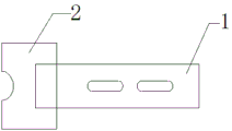
The utility model relates to a novel tool apron device for a grooving machine. The novel tool apron device comprises a tool rest and a tool installing base. The tool rest is connected with the tool installing base, the tool installing base is made of copper, two hole grooves are formed in the tool rest, and a groove opening is formed in the tool installing base. Compared with the prior art, the novel tool apron device improves the equipment use ratio, achieves the 99% grooving finished product rate of thick paper boards with the thickness of more than 3mm, saves cost and improves the production efficiency.
Description
Technical field
The utility model relates to the printing packaging field, is specially a kind of device of Novel cutter holder for groover.
Background technology
The tool apron device of the groover of printing enterprise's use at present is all to have adopted two kinds of fixing tool rests (90 degree and 120 degree), and it is bad that the Cardboard Paper included angle causes product not aborning, and fraction defective is high, and this method human cost is high, and production efficiency is low.
The utility model content
The technical problem that the utility model solves is to provide a kind of device of Novel cutter holder for groover, to solve the problem that proposes in the above-mentioned background technology.
The technical problem that the utility model solves realizes by the following technical solutions:
A kind of device of Novel cutter holder for groover, comprise knife rest, dress cutter base; Described knife rest is connected with dress cutter base; The material of described dress cutter base is copper; Two hole slots are arranged on described knife rest; On described dress cutter base, notch is arranged.
Further, the hole slot on described knife rest is shaped as oblateness.
Further, the notch on described dress cutter base is two kinds of bar shaped, semicircles.
Beneficial effect
Compared with prior art, the utility model has improved the utilization rate of equipment, has realized the effect of the above Cardboard Paper fluting of 3mm finished product 99%, saves cost, and production efficiency improves.
Description of drawings
Fig. 1 is structural representation of the present utility model;
Fig. 2 is front view of the present utility model.
The specific embodiment
Of the present utility modelly to realize technological means, creation characteristic in order making, to reach purpose and effect is easy to understand,, below in conjunction with concrete diagram, further set forth the utility model.
As shown in Figure 1, a kind of device of Novel cutter holder for groover, comprise knife rest 1, dress cutter base 2; Described knife rest 1 is connected with dress cutter base 2; The material of described dress cutter base 2 is copper; Two hole slots are arranged on described knife rest 1; On described dress cutter base, notch is arranged.
Further, the hole slot on described knife rest 1 is shaped as oblateness.
Further, the notch on described dress cutter base 2 is two kinds of bar shaped, semicircles.
Above demonstration and described basic principle of the present utility model and principal character and advantage of the present utility model.The technical staff of the industry should understand; the utility model is not restricted to the described embodiments; that describes in above-described embodiment and specification just illustrates principle of the present utility model; under the prerequisite that does not break away from the utility model spirit and scope; the utility model also has various changes and modifications, and these changes and improvements all fall in claimed the utility model scope.Claimed scope of the present utility model is defined by appending claims and equivalent thereof.
Claims (3)
1. a Novel cutter holder device that is used for groover, is characterized in that, comprises knife rest, dress cutter base; Described knife rest is connected with dress cutter base; The material of described dress cutter base is copper; Two hole slots are arranged on described knife rest; On described dress cutter base, notch is arranged.
2. a kind of device of Novel cutter holder for groover according to claim 1, is characterized in that, the hole slot on described knife rest is shaped as oblateness.
3. a kind of device of Novel cutter holder for groover according to claim 1, is characterized in that, the notch on described dress cutter base is two kinds of bar shaped, semicircles.
Priority Applications (1)
| Application Number | Priority Date | Filing Date | Title |
|---|---|---|---|
| CN2013203171953U CN203282537U (en) | 2013-06-04 | 2013-06-04 | Novel tool apron device for grooving machine |
Applications Claiming Priority (1)
| Application Number | Priority Date | Filing Date | Title |
|---|---|---|---|
| CN2013203171953U CN203282537U (en) | 2013-06-04 | 2013-06-04 | Novel tool apron device for grooving machine |
Publications (1)
| Publication Number | Publication Date |
|---|---|
| CN203282537U true CN203282537U (en) | 2013-11-13 |
Family
ID=49538916
Family Applications (1)
| Application Number | Title | Priority Date | Filing Date |
|---|---|---|---|
| CN2013203171953U Expired - Fee Related CN203282537U (en) | 2013-06-04 | 2013-06-04 | Novel tool apron device for grooving machine |
Country Status (1)
| Country | Link |
|---|---|
| CN (1) | CN203282537U (en) |
-
2013
- 2013-06-04 CN CN2013203171953U patent/CN203282537U/en not_active Expired - Fee Related
Similar Documents
| Publication | Publication Date | Title |
|---|---|---|
| CN204640358U (en) | Heavy-gauge sheeting perforating device | |
| CN204059062U (en) | Curtain puncher | |
| CN202593947U (en) | Automatic paper spreading device | |
| CN203956981U (en) | A kind of paper cutter | |
| CN203282537U (en) | Novel tool apron device for grooving machine | |
| CN203471830U (en) | Hard paperboard cutting machine with conveying function | |
| CN207007591U (en) | Test-strips cut tool | |
| CN203438340U (en) | Wood chip cutting automatic feeding device | |
| CN205735276U (en) | A kind of colour atla puncher | |
| CN204183651U (en) | A kind of roller cutter machine Pressure gauge adjusting device | |
| CN206855614U (en) | A kind of two-sided cross cutting integrated mould | |
| CN204720752U (en) | First backshank shut-off mechanism of six pin female pin machines side by side | |
| CN103586924A (en) | Cutting die device | |
| CN204169326U (en) | A kind of industrial design is with making frame | |
| CN203691752U (en) | Circuit board with improved connecting plate structure | |
| CN202742800U (en) | Online slitting forming device for gravure printing machine | |
| CN204112144U (en) | The thread cutter of anti-yarn resilience | |
| CN203542721U (en) | Combined cutter die | |
| CN203682730U (en) | Automatic adhesive tape sticking mechanism | |
| CN204295772U (en) | A kind of cutting die device for FPC cutting | |
| CN203282225U (en) | Rapid drilling clamp | |
| CN202819754U (en) | Auxiliary adhesive interlining cutting tool | |
| CN201872206U (en) | Perforation jig | |
| CN202862302U (en) | Board dividing fixture for printed circuit board | |
| CN207606187U (en) | A kind of two sides cutting edge of a knife or a sword of falling beryllium stamping die |
Legal Events
| Date | Code | Title | Description |
|---|---|---|---|
| C14 | Grant of patent or utility model | ||
| GR01 | Patent grant | ||
| CF01 | Termination of patent right due to non-payment of annual fee |
Granted publication date: 20131113 Termination date: 20150604 |
|
| EXPY | Termination of patent right or utility model |