CN203277786U - Module fixing frame structure - Google Patents
Module fixing frame structure Download PDFInfo
- Publication number
- CN203277786U CN203277786U CN 201320047557 CN201320047557U CN203277786U CN 203277786 U CN203277786 U CN 203277786U CN 201320047557 CN201320047557 CN 201320047557 CN 201320047557 U CN201320047557 U CN 201320047557U CN 203277786 U CN203277786 U CN 203277786U
- Authority
- CN
- China
- Prior art keywords
- chassis body
- module
- frame
- slip
- slip frame
- Prior art date
- Legal status (The legal status is an assumption and is not a legal conclusion. Google has not performed a legal analysis and makes no representation as to the accuracy of the status listed.)
- Expired - Lifetime
Links
Images


Landscapes
- Mirrors, Picture Frames, Photograph Stands, And Related Fastening Devices (AREA)
Abstract
The utility model discloses a module fixing frame structure, including a frame body and sliding frames on both sides. A space structure formed by the frame body and the sliding frames on both sides is used for accommodating one or more modules. The frame body and the sliding frames are provided with a plurality of grooves. Both sides of each module are provided with positioning bosses corresponding to the grooves. The sliding frames on both sides are closed and locked, so that the positioning bosses of the modules are blocked in sealed grooves formed by cooperation of the frame body and the sliding frames. When the sliding frames are released, the module is easily inserted, and then the sliding frames are closed. The actions can achieve fixing of the module. The module fixing frame structure has the advantages that the module is disassembled easily and is fixed stably.
Description
Technical field
The utility model discloses a kind of module stationary frame structure, divides the fixture technical field that belongs to connecting module by International Patent Classification (IPC) (IPC).
Background technology
Fixed frame is to be used for fixing the socket connection module, can be equipped with different link blocks.China document CN1191400A discloses a kind of fixed frame that patches link block that is used for fixing, and fixed frame wherein is made of two half frames that are hinged, but its module installation guiding is poor, and the location is difficult, installs to bother; Document FR2781312A3 discloses a kind of module connecting frame, and plastic frame wherein is annex, and frame is independent of outside framework before module is installed, and module is packed into after framework, and it is by both sides plastic frame stuck-module, poor reliability; CN 201656115 U disclose a kind of positioning device for connector module, the posting dual-side is provided with more than one T shape short slot, there is enchasing plate the connector modules two sides, this enchasing plate one end coordinates the location to form a T shape grab with described short slot, the other end extends the connector modules body and forms a press section, and this structure has increased structural complexity, the poor compatibility of module.
Summary of the invention
For the deficiencies in the prior art, the utility model provides a kind of module stationary frame structure rational in infrastructure, is to be used for fixing module to connect housing or be locked in framework on panel with being connected into to patch.
For achieving the above object, the utility model is achieved through the following technical solutions:
A kind of module stationary frame structure, the slip frame that comprises chassis body and both sides, chassis body and both sides slip frame cunning are established and are connected and surround space structure and be used for holding more than one module, each module both sides are equipped with positioner, chassis body is provided with the slip frame some grooves or the hole that coordinates, positioner on module is inserted in the groove or hole of chassis body, closed also lock both sides slip frame, make the positioner of module be stuck in the closed pockets of chassis body and the formation of sliding edge frame or hole to realize the purpose of stuck-module.
Further, the positioner of described module is the boss of module both sides, boss is divided into big or small side with the identification module installation direction, realizes the location in the closed pockets that above-mentioned boss insertion chassis body and sliding edge frame form or hole, the size in groove or hole and boss size side corresponding matching.
Further, described slip frame two ends are respectively equipped with leads platform, chassis body is provided with the guide groove that matches, the slip frame lead the guide groove that platform is inserted into chassis body, be provided with buckle on the mating surface at slip frame and chassis body two ends, the sidewall indentation, there that the slippage of slip frame puts in place and namely is stuck in chassis body, described slip frame can be realized the slippage fit structure and can directly not deviate from the guide surface of chassis body.
Further, described slip frame and chassis body two sides are connected as a single entity to strengthen the longitudinal stress intensity of slip lid by the T-shaped structure embedding that cooperatively interacts.
Further, at least two T-shaped hooks are extended in described slip frame lower edge, and the chassis body corresponding position is provided with T-shaped groove, and the slippage of slip frame puts in place namely fixed with chassis body embedding fixed.
Further, described two slip frames are provided with the screwed hole of cooperation, and two slip frames slide onto when forming the groove of sealing or hole with chassis body by screw locking and with chassis body along the guide surface of chassis body and form the space structure of stuck-module.
The utility model fixed frame is to be used for fixing module to connect housing or be locked in framework on panel with being connected into to patch.When fixed frame is used for fixing module, be to be stuck in groove on framework by the boss on module to realize.Fixed frame comprises chassis body and two slip frames, at first module is inserted in the groove of chassis body, the slip frame that then will be encased in advance on chassis body is closed, patches like this link block and just firmly is fixed in the groove of the formed sealing of triple interaction.The utility model has the advantage of: insert module like a cork when unclamping the slip frame, closed slip frame then, above action just can realize stuck-module, this structure dismounting module is convenient, can play again the stable effect of module of fixing.
Description of drawings
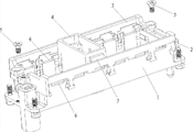
Fig. 1 is the utility model structural representation.
Fig. 2 is the view that the utility model is installed the slip frame.
Fig. 3 is the view that installs after the slip frame.
View when Fig. 4 is installation module.
Figure .5 is the view after closed slip frame.
Embodiment
The utility model is described in further detail below in conjunction with accompanying drawing:
embodiment: see also Fig. 1 to Fig. 5, a kind of module stationary frame structure, the slip frame 2 that comprises chassis body 1 and both sides, 3, chassis body 1 and both sides slip frame 2, 3 space structures that surround are used for holding one or more module 4, chassis body 1 and slip frame 2, 3 junctions are provided with some grooves 6 or the hole of cooperation, each module 4 both sides are provided with the positioner corresponding with above-mentioned groove or hole, positioner on module is inserted in the groove or hole of chassis body, closure is also locked both sides slip frame 2, 3, make the positioner of module be stuck in the purpose that namely realizes stuck-module in the groove 6 of the sealing that chassis body and slip frame complement each other to form or hole.The positioner of module 4 can be boss 7 or the projection of module both sides, boss or projection are divided into big or small side with the identification module installation direction, insert when it is installed in chassis body 1 and slip frame 2,3 closed pockets 6 that form or hole and realize the location, the size in groove or hole and boss size side corresponding matching.Be respectively equipped with at slip frame 2,3 two ends and lead platform 9, chassis body 1 is provided with the guide groove 8 that matches, the slip frame lead the guide groove 8 that platform 9 is inserted into chassis body, be provided with buckle 10 on the mating surface at slip frame and chassis body two ends, sidewall breach 11 places that the slippage of slip frame puts in place and namely is stuck in chassis body, described slip frame 2,3 can be realized the slippage fit structure and can directly not deviate from the guide surface 12 of chassis body is interior.Slip frame and chassis body two sides are connected as a single entity by T-shaped structure 13 embeddings that cooperatively interact and namely strengthen the longitudinal stress intensity of slip lid with the anti-skidding frame to top offset.At least two T-shaped hooks (in Fig. 1 being three) are extended in slip frame lower edge, and the chassis body corresponding position is provided with T-shaped groove, and the slippage of slip frame puts in place namely fixed with chassis body embedding fixed.Two slip frames of the present utility model are provided with the screwed hole of cooperation, and two slip frames slide onto when forming the groove of sealing or hole with chassis body by screw 5 lockings and with chassis body along the guide surface of chassis body and form the space structure of stuck-module.
The concrete installation process of the utility model is as follows:
1, made guide groove 8 on chassis body 1, do respectively the boss (leading platform 9) of guiding on slip frame 2,3, at first the boss on the slip frame is inserted into 8 li of the guide grooves of chassis body 1, then slip frame 2,3 is pushed away inward, boss slides into along guide groove 8 immediately; In addition, done buckle 10 on the slip frame, the slip frame slides on the sidewall breach 11 that rear buckle 10 just is stuck in chassis body 1, makes slip frame 2,3 not spin off from chassis body 1.So far, Fig. 2 is seen in slip frame 2,3 installations;
2, install slip frame 2,3 after, the slip frame can be free to slide on the guide surface 12 in chassis body 1, sees Fig. 3;
3, be next installation module.The boss 7 of module 4 is inserted into 6 li of the grooves of chassis body 1.This process is installation module, moves lightly easyly, sees Fig. 4;
4, final step is closed slip frame 2,3, makes the groove that forms sealing between the three, thus the module of fixing.First slip frame 2,3 is pushed away inward along guide surface 12, then lock screw 5, just module 4 is fixed firmly by cooperatively interacting between the three like this.Secondly, slip frame 2,3 coordinates by T-shaped groove with chassis body 1, has prevented that effectively the slip frame up is subjected to displacement.So far, all installation processes finish, and see Fig. 5.
The utility model fixed frame is to be used for fixing module to connect housing or be locked in framework on panel with being connected into to patch.When fixed frame is used for fixing module, be to be stuck in groove on framework by the boss on module to realize.Therefore, advise the structure of fixed frame as shown in Figure 1: fixed frame comprises chassis body 1 and slip frame 2,3, at first module 4 is inserted in the groove of chassis body 1, then will be encased in advance slip frame 2,3 closures on chassis body 1, and patch like this link block and just firmly be fixed in the groove of the formed sealing of triple interaction.
The above record, only for utilizing the embodiment of this origination techniques content, modification, variation that any those skilled in the art use this creation to do all belong to the scope of the claims that this creation is advocated, and are not limited to those disclosed embodiments.
Claims (6)
1. module stationary frame structure, it is characterized in that: the slip frame that comprises chassis body and both sides, chassis body and both sides slip frame cunning are established and are connected and surround space structure and be used for holding one or more module, each module both sides are equipped with positioner, chassis body is provided with the slip frame some grooves or the hole that coordinates, positioner on module is inserted in the groove or hole of chassis body, closed also lock both sides slip frame, make the positioner of module be stuck in closed pockets that chassis body and sliding edge frame form or hole realization and locate.
2.
According toModule stationary frame structure claimed in claim 1 is characterized in that: the positioner of described module is the boss of module both sides, and above-mentioned boss inserts in the big or small corresponding closed pockets or hole of chassis body and the formation of sliding edge frame.
3.
According toModule stationary frame structure claimed in claim 1, it is characterized in that: described slip frame two ends are respectively equipped with leads platform, chassis body is provided with the guide groove that matches, the slip frame lead the guide groove that platform is inserted into chassis body, be provided with buckle on the mating surface at slip frame and chassis body two ends, the sidewall indentation, there that the slippage of slip frame puts in place and namely is stuck in chassis body, described slip frame can be realized the slippage fit structure and can directly not deviate from the guide surface of chassis body.
4.
According toThe described module stationary frame structure of one of claims 1 to 3 is characterized in that: described slip frame and chassis body two sides are connected as a single entity to strengthen the longitudinal stress intensity of slip lid by the T-shaped structure embedding that cooperatively interacts.
5.
According toModule stationary frame structure claimed in claim 4 is characterized in that: at least two T-shaped hooks are extended in described slip frame lower edge, and the chassis body corresponding position is provided with T-shaped groove, and the slippage of slip frame puts in place namely fixed with chassis body embedding fixed.
6.
According toClaim 1 or 2 or 3 or 5 described module stationary frame structures, it is characterized in that: described two slip frames are provided with the screwed hole of cooperation, and two slip frames slide onto when forming the groove of sealing or hole with chassis body by screw locking and with chassis body along the guide surface of chassis body and form the space structure of stuck-module.
Priority Applications (1)
| Application Number | Priority Date | Filing Date | Title |
|---|---|---|---|
| CN 201320047557 CN203277786U (en) | 2013-01-29 | 2013-01-29 | Module fixing frame structure |
Applications Claiming Priority (1)
| Application Number | Priority Date | Filing Date | Title |
|---|---|---|---|
| CN 201320047557 CN203277786U (en) | 2013-01-29 | 2013-01-29 | Module fixing frame structure |
Publications (1)
| Publication Number | Publication Date |
|---|---|
| CN203277786U true CN203277786U (en) | 2013-11-06 |
Family
ID=49508118
Family Applications (1)
| Application Number | Title | Priority Date | Filing Date |
|---|---|---|---|
| CN 201320047557 Expired - Lifetime CN203277786U (en) | 2013-01-29 | 2013-01-29 | Module fixing frame structure |
Country Status (1)
| Country | Link |
|---|---|
| CN (1) | CN203277786U (en) |
Cited By (16)
| Publication number | Priority date | Publication date | Assignee | Title |
|---|---|---|---|---|
| EP3067993A1 (en) * | 2015-03-11 | 2016-09-14 | Phoenix Contact GmbH & Co. KG | Supporting frame for holding modular contact inserts |
| DE102015103563A1 (en) * | 2015-03-11 | 2016-09-15 | Phoenix Contact Gmbh & Co. Kg | Holding frame for receiving modular contact inserts |
| WO2016150565A1 (en) * | 2015-03-26 | 2016-09-29 | Amphenol-Tuchel Electronics Gmbh | Modular plug connector system |
| CN106654687A (en) * | 2016-12-06 | 2017-05-10 | 沈阳兴华华亿轨道交通电器有限公司 | Bracket for fixing modularized insulator and used in connector |
| CN106848753A (en) * | 2017-02-28 | 2017-06-13 | 深圳市长盈精密技术股份有限公司 | Fixator for connector |
| DE102016213251A1 (en) * | 2016-07-20 | 2018-01-25 | Harting Electric Gmbh & Co. Kg | Holding frame arrangement with base frame and fixing element and assembly process |
| CN108352648A (en) * | 2015-11-16 | 2018-07-31 | 哈廷电子有限公司及两合公司 | Holding frame for keeping umbilical connector module |
| US20180254591A1 (en) * | 2013-12-12 | 2018-09-06 | Harting Electric Gmbh & Co. Kg | Holding frame for a plug-type connector |
| WO2018192616A1 (en) * | 2017-04-20 | 2018-10-25 | Harting Electric Gmbh & Co. Kg | Retaining frame for a plug connector, and equipping method |
| CN109075490A (en) * | 2016-04-21 | 2018-12-21 | 菲尼克斯电气公司 | The plug-in connector component of modular contact inserts with insertion retainer |
| CN109643866A (en) * | 2016-06-23 | 2019-04-16 | 哈廷电子有限公司及两合公司 | Holding frame and its method for providing for connectors |
| CN109755798A (en) * | 2017-11-06 | 2019-05-14 | 哈廷电子有限公司及两合公司 | Modularization for connectors keeps frame |
| CN110537298A (en) * | 2017-04-20 | 2019-12-03 | 哈廷电子有限公司及两合公司 | Holding frame and its assembly method for pluging connector |
| DE102018131512A1 (en) * | 2018-12-10 | 2020-06-10 | Harting Electric Gmbh & Co. Kg | Pressure resistant connector |
| US10686278B2 (en) | 2016-07-20 | 2020-06-16 | Harting Electric Gmbh & Co. Kg | Multi-part retaining frame, method for assembling and equipping |
| CN113178729A (en) * | 2021-04-13 | 2021-07-27 | 厦门唯恩电气有限公司 | Module fixing frame |
-
2013
- 2013-01-29 CN CN 201320047557 patent/CN203277786U/en not_active Expired - Lifetime
Cited By (33)
| Publication number | Priority date | Publication date | Assignee | Title |
|---|---|---|---|---|
| US20180254591A1 (en) * | 2013-12-12 | 2018-09-06 | Harting Electric Gmbh & Co. Kg | Holding frame for a plug-type connector |
| US10424892B2 (en) | 2013-12-12 | 2019-09-24 | Harting Electric Gmbh & Co. Kg | Holding frame for a plug-type connector |
| US10554007B2 (en) | 2013-12-12 | 2020-02-04 | Harting Electric Gmbh & Co. Kg | Holding frame for a plug-type connector |
| US10418773B2 (en) | 2013-12-12 | 2019-09-17 | Harting Electric Gmbh & Co. Kg | Holding frame for a plug-type connector |
| EP3067993A1 (en) * | 2015-03-11 | 2016-09-14 | Phoenix Contact GmbH & Co. KG | Supporting frame for holding modular contact inserts |
| DE102015103563B4 (en) * | 2015-03-11 | 2020-08-20 | Phoenix Contact Gmbh & Co. Kg | Holding frame for holding modular contact inserts |
| DE102015103563A1 (en) * | 2015-03-11 | 2016-09-15 | Phoenix Contact Gmbh & Co. Kg | Holding frame for receiving modular contact inserts |
| CN107710518A (en) * | 2015-03-26 | 2018-02-16 | 安费诺-图赫尔电子有限公司 | Modular connectors system |
| WO2016150565A1 (en) * | 2015-03-26 | 2016-09-29 | Amphenol-Tuchel Electronics Gmbh | Modular plug connector system |
| CN108352648A (en) * | 2015-11-16 | 2018-07-31 | 哈廷电子有限公司及两合公司 | Holding frame for keeping umbilical connector module |
| CN108352648B (en) * | 2015-11-16 | 2020-02-04 | 哈廷电子有限公司及两合公司 | Holding frame for holding plug-in connector modules |
| CN109075490A (en) * | 2016-04-21 | 2018-12-21 | 菲尼克斯电气公司 | The plug-in connector component of modular contact inserts with insertion retainer |
| CN109643866B (en) * | 2016-06-23 | 2020-08-28 | 哈廷电子有限公司及两合公司 | Holding frame for a plug connector and method for assembling same |
| CN109643866A (en) * | 2016-06-23 | 2019-04-16 | 哈廷电子有限公司及两合公司 | Holding frame and its method for providing for connectors |
| CN109716593B (en) * | 2016-07-20 | 2020-09-22 | 哈廷电子有限公司及两合公司 | Holding frame assembly with a base frame and a fastening element and method for assembling the same |
| US10686278B2 (en) | 2016-07-20 | 2020-06-16 | Harting Electric Gmbh & Co. Kg | Multi-part retaining frame, method for assembling and equipping |
| CN109716593A (en) * | 2016-07-20 | 2019-05-03 | 哈廷电子有限公司及两合公司 | Holding frame assembly with pedestal and fixing element and the method for assembling it |
| DE102016213251A1 (en) * | 2016-07-20 | 2018-01-25 | Harting Electric Gmbh & Co. Kg | Holding frame arrangement with base frame and fixing element and assembly process |
| CN106654687A (en) * | 2016-12-06 | 2017-05-10 | 沈阳兴华华亿轨道交通电器有限公司 | Bracket for fixing modularized insulator and used in connector |
| CN106848753A (en) * | 2017-02-28 | 2017-06-13 | 深圳市长盈精密技术股份有限公司 | Fixator for connector |
| WO2018192616A1 (en) * | 2017-04-20 | 2018-10-25 | Harting Electric Gmbh & Co. Kg | Retaining frame for a plug connector, and equipping method |
| CN110537298A (en) * | 2017-04-20 | 2019-12-03 | 哈廷电子有限公司及两合公司 | Holding frame and its assembly method for pluging connector |
| CN110537297A (en) * | 2017-04-20 | 2019-12-03 | 哈廷电子有限公司及两合公司 | The method for keeping frame and assembling to keep frame for pluging connector |
| US11038304B2 (en) | 2017-04-20 | 2021-06-15 | Harting Electric Gmbh & Co. Kg | Holding frame for a plug connector and methods of populating same |
| CN110537298B (en) * | 2017-04-20 | 2022-01-11 | 哈廷电子有限公司及两合公司 | Holding frame for a plug connector and method for assembling the same |
| CN110537297B (en) * | 2017-04-20 | 2022-04-05 | 哈廷电子有限公司及两合公司 | Holding frame for a plug connector and method for assembling a holding frame |
| CN114597692A (en) * | 2017-04-20 | 2022-06-07 | 哈廷电子有限公司及两合公司 | Holding frame for a plug connector and method for assembling a holding frame |
| US11552425B2 (en) | 2017-04-20 | 2023-01-10 | Harting Electric Gmbh & Co. Kg | Holding frame for a plug connector and methods of populating same |
| CN109755798A (en) * | 2017-11-06 | 2019-05-14 | 哈廷电子有限公司及两合公司 | Modularization for connectors keeps frame |
| CN109755798B (en) * | 2017-11-06 | 2022-01-18 | 哈廷电子有限公司及两合公司 | Modular holding frame for a plug connector |
| DE102018131512A1 (en) * | 2018-12-10 | 2020-06-10 | Harting Electric Gmbh & Co. Kg | Pressure resistant connector |
| CN113178729A (en) * | 2021-04-13 | 2021-07-27 | 厦门唯恩电气有限公司 | Module fixing frame |
| CN113178729B (en) * | 2021-04-13 | 2024-05-03 | 厦门唯恩电气有限公司 | Module fixing frame |
Similar Documents
| Publication | Publication Date | Title |
|---|---|---|
| CN203277786U (en) | Module fixing frame structure | |
| CN202111314U (en) | Locking device | |
| CN205427250U (en) | Optical module release mechanism | |
| CN203414632U (en) | Electronic tag installation device and optical fiber connector employing electronic tag installation device | |
| CN206297366U (en) | Cover plate installation structure and vehicle | |
| CN202725988U (en) | Box locking clamp for sand box | |
| CN105425342A (en) | Fiber plug and delocking structure thereof | |
| CN201915697U (en) | Anti-theft lock with hidden lock cylinder | |
| CN204315819U (en) | A kind of Novel lock catch mechanism for high-tension connector | |
| CN205594555U (en) | Self-locking structure of server module case | |
| CN205052032U (en) | Fixing structure | |
| CN202850668U (en) | Plane lock with mountable label | |
| CN206743181U (en) | Snap lock structure | |
| CN203232996U (en) | Data module capable of being installed without tool | |
| CN201781243U (en) | Power line clamp | |
| CN204741359U (en) | Car lights motor of adjusting luminance | |
| CN203418630U (en) | Inorganic fireproof heat insulation plate forming mold | |
| CN203135107U (en) | CPU connector | |
| CN205030017U (en) | Module installation structure | |
| CN204161224U (en) | With the baggage rack of card slot type structure | |
| CN203386426U (en) | RFID (radio frequency identification) locking seal with plastic shell | |
| CN207457558U (en) | A kind of CFP2 optoelectronic transceivers device | |
| CN205543400U (en) | An organic whole 3. 1 type -C rubber bases of USB of moulding plastics | |
| CN207847279U (en) | A kind of bedroom door anti-theft device | |
| CN203101691U (en) | Safe and durable fiber-to-the-home distribution apparatus convenient to mount |
Legal Events
| Date | Code | Title | Description |
|---|---|---|---|
| C14 | Grant of patent or utility model | ||
| GR01 | Patent grant | ||
| CX01 | Expiry of patent term |
Granted publication date: 20131106 |
|
| CX01 | Expiry of patent term |