CN203275693U - Light guide plate with holes, and stereo assembly formed by same - Google Patents

Light guide plate with holes, and stereo assembly formed by same Download PDF

Info

Publication number
CN203275693U
CN203275693U CN 201320158888 CN201320158888U CN203275693U CN 203275693 U CN203275693 U CN 203275693U CN 201320158888 CN201320158888 CN 201320158888 CN 201320158888 U CN201320158888 U CN 201320158888U CN 203275693 U CN203275693 U CN 203275693U
Authority
CN
China
Prior art keywords
light
guide plate
light guide
holes
hole
Prior art date
Legal status (The legal status is an assumption and is not a legal conclusion. Google has not performed a legal analysis and makes no representation as to the accuracy of the status listed.)
Expired - Fee Related
Application number
CN 201320158888
Other languages
Chinese (zh)
Inventor
刘锡
Current Assignee (The listed assignees may be inaccurate. Google has not performed a legal analysis and makes no representation or warranty as to the accuracy of the list.)
Yuanbangjin Science and Technology Research Center (Guangzhou) Co., Ltd.
Original Assignee
Shenzhen Onwing Optoelectronics Products Co Ltd
Priority date (The priority date is an assumption and is not a legal conclusion. Google has not performed a legal analysis and makes no representation as to the accuracy of the date listed.)
Filing date
Publication date
Application filed by Shenzhen Onwing Optoelectronics Products Co Ltd filed Critical Shenzhen Onwing Optoelectronics Products Co Ltd
Priority to CN 201320158888 priority Critical patent/CN203275693U/en
Application granted granted Critical
Publication of CN203275693U publication Critical patent/CN203275693U/en
Anticipated expiration legal-status Critical
Expired - Fee Related legal-status Critical Current

Links

Images

Abstract

The utility model discloses a light guide plate with holes, and a stereo assembly formed by the same. The light guide plate with the holes comprises a plate body (1) and a light source (3) which is arranged at a side edge of the plate body. At least one side surface of the plate body is provided with light guide holes (2). The utility model also provides differently-shaped stereo assemblies formed by the light guide plate with the holes. A surface of the light guide plate of the utility model is provided with various fine holes; the perforating in the light guide plate and different perforated direction are used to regulate and control the light distribution curve (the light distribution curve of a conventional light guide plate is fixed); the defect that the conventional light guide plate must rely on the diffuser plate to serve as the LED panel lamp is prevented; and the practicality and the artistry of the light guide plate are improved.

Description

A kind of light guide plate with holes reaches by its solid component that consists of
Technical field
The utility model relates to the light conduction device, relates in particular to a kind of light guide plate that is applicable to the aspects such as all kinds of illuminations, artistic lighting and decorative lighting, ornament materials, show window, cabinet, show stand.
Background technology
The light guide plate design concept comes from the LCDs of notebook computer.Light guide plate adopts fluorescent light, CCFL, LED light source to see through by light guiding points or leaded light groove after optical principle calculating, under reflective membrane (reflecting plate) and diffusion barrier effect, changes line source or pointolite into area source.For making the light guide plate can uniformly light-emitting, must be by various densitys, light guiding points not of uniform size, basic identical toward the efficient of all directions reflection to guarantee light.The purposes of reflector plate (reflecting plate) is the light reflection of bottom surface of light guide plate reveals is returned in light guide plate, is used for improving the service efficiency of light, improves brightness.The effect of diffusion barrier is to make light more even softer.Being of wide application of light guide plate is as light-guide illumination, decorative lighting, artistic lighting, TV backlight, advertisement, sign board etc.The light guiding points of existing light guide plate is all the surface that is attached to light guide plate, and light guiding points is made the modes such as radium-shine laser, silk-screen, corrosion that comprise, and is dull unchanged, can not change the curve of luminous intensity distribution.
Summary of the invention
The utility model is unchanged for the light guiding points dullness that solves existing light guide plate, can not change the Curve Technique problem of luminous intensity distribution, proposes a kind of light guide plate with holes that can change distribution curve flux.
The light guide plate a kind of with holes that the utility model provides, the light source that it comprises plate body and is located at the plate body side, at least one side of described plate body is provided with light-conductive hole.
More excellent, described light-conductive hole is at least a kind of of blind hole or through hole.
More excellent, described light-conductive hole is at least a kind of of upright opening or angling hole.
More excellent, described light-conductive hole is at least a kind of of circular hole, elliptical aperture or polygonal hole.
More excellent, described light-conductive hole big or small identical or not identical.
More excellent, on the openning of described light-conductive hole or the other plate body of light-conductive hole be provided with light guiding points.
More excellent, described light-conductive hole is located at a side of described plate body, and the another side of plate body is provided with light guiding points.
More excellent, described light-conductive hole and/or light guiding points consist of the leaded light site, and difformity, different size or different densities distribute leaded light site constitutes various picture and text structures.
The utility model also proposes a kind of difform solid component that utilizes light guide plate with holes to consist of.
The utility model is produced all kinds of pores on the surface of light guide plate, utilization is bored a hole in light guide plate, and direction with perforation is different regulates and controls distribution curve flux (distribution curve flux of traditional light guide plate is fixed), the solution light guide plate must rely on diffuser plate could as the way of LED panel light, improve practicality and the artistry of light guide plate.Utilize the utility model to substitute the light fixture of traditional LED light guide plate panel light, can greatly improve the market competitiveness.
Compared with prior art, advantage of the present utility model:
(1) existing light guide plate range of application is narrow, also limits much at design aspect, and the materials'use aspect must be combined with the problem that diffusion material could solve all kinds of dazzles.The utility model can not use diffusion material fully and solves glare problem, and after the cancellation diffusion material, light is directly derived light by diffuse way by all kinds of pores in light guide plate, reduces energy consumption, improves light efficiency, reduces costs (reducing the material costs such as light source and diffusion);
(2) the utility model application is more extensive, has value of art appreciation, not only can be used for illumination, also can be used for ornament, handicraft etc.Its light evenly soft, profile vividly attractive in appearance, shape is ever-changing, stereoscopic sensation is stronger, extended LED coordinates that light guide plate plays a greater role at the key lighting product line, more energy-conserving and environment-protective.Product is widely used in various commercial illumination, artistic lighting, decorative lighting, handicraft, the artwork, furniture illumination, ornament materials, advertising lighting, show window, cabinet, show stand, goes out the fields such as guideboard, guide plate.
Description of drawings
Fig. 1, Fig. 2 are respectively the front schematic view of the utility model rectangular light guide plate and circular light guide plate;
Fig. 3 is provided with the cut-open view that through hole and a side are provided with the light guide plate of blind hole;
Fig. 4 is provided with the cut-open view that through hole and two sides are provided with the light guide plate of blind hole;
Fig. 5 is the cut-open view that a side is provided with the light guide plate of vertical blind hole;
Fig. 6 is the cut-open view of the light guide plate of the side inclination blind hole that is provided with different directions;
Fig. 7 is the cut-open view of the light guide plate of the side inclination blind hole that is provided with vertical blind hole and different directions;
Fig. 8 is the cut-open view that the blind hole mouth of a side is provided with the light guide plate of light guiding points;
Fig. 9 is the other cut-open view that is provided with the light guide plate of light guiding points of the blind hole mouth of a side;
Figure 10 is that a side is provided with the cut-open view that blind hole and another side are provided with the light guide plate of light guiding points;
Figure 11 a is that a side is provided with the cut-open view that light-conductive hole and another side are provided with the light guide plate of light guiding points;
Figure 11 b is the left surface view of Figure 11 a;
Figure 11 c is the right flank view of Figure 11 a.
Embodiment
As Fig. 1~shown in Figure 10, the light guide plate with holes that the utility model proposes, the light source 3 that it comprises plate body 1 and is located at the plate body side, at least one side of described plate body is provided with light-conductive hole 2.
See also Fig. 3, Fig. 4, the utility model light-conductive hole 2 can be also the mixing setting of blind hole and through hole for a side of being located at light guide plate 1 or the blind hole (different depth) of two sides, can also be all through hole.See also Fig. 5~Fig. 7, described blind hole or through hole 2 can be upright opening or angling hole, can be also the mixing settings of upright opening (90 degree) and angling hole (as 45 degree, 35 degree etc.).Light-conductive hole 2 shapes can be for circular hole, elliptical aperture or polygonal hole a kind of, can be also any mixing setting of upright opening, inclined hole or polygonal hole.The pore size of light-conductive hole 2 can be identical, also can be not identical.
As Fig. 8, shown in Figure 9, can be provided with light guiding points 4 on the openning of light-conductive hole 2.Also can be provided with light guiding points 4 on the plate body 1 on light-conductive hole 2 sides.As required, on the plate body 1 that light guiding points 4 can also be arranged on the openning of light-conductive hole 2 simultaneously and light-conductive hole 2 is other.As shown in figure 10, light-conductive hole 2 is located at the left surface of described plate body 1, and the right flank of plate body 1 is provided with light guiding points 4.
See also Figure 11 b, Figure 11 c, light-conductive hole 2 and/or light guiding points 4 consists of the leaded light site, and difformity, different size or different densities distribute leaded light site can constitute various picture and text structures.
Utilize light guide plate with holes of the present utility model can make the light fixture of difform solid component.
The method for making of the light guide plate with holes that the utility model proposes, its step is as follows:
Figure 11 a, Figure 11 b and Figure 11 c are depicted as the utility model one preferred embodiment.
Step 1: according to market demand, first layout (consulting Figure 11 b, Figure 11 c).Again this pattern is resolved into: be used in the partial pattern of light guide plate 1 left surface making light-conductive hole 2 with for the partial pattern of making light guiding points 4 at light guide plate 1 right flank.In the present embodiment, light guiding points 4 adopts serigraphy, makes so this partial pattern will be carried out half tone.
Step 2: will be placed in the left-hand face of light guide plate 1 for the pattern of making light-conductive hole, and utilize laser equipment to make the mixture of vertical blind hole 2 and inclination blind hole 2, as shown in Figure 11 a.The recycling half tone carries out serigraphy in the right lateral surface of light guide plate 1 and makes light guiding points 4.Light-conductive hole 2 and light guiding points 4 forms leaded light site, these whole structures (consulting Figure 11 b, Figure 11 c) that just can show layout in leaded light site.
After pros and cons completes, can see complete, a three-dimensional pattern, light guide plate can be sent space pattern after a bright light, improve brightness and sight, the leaded light site is provided with the leaded light site that difformity, different size or different densities distribute, and difformity, different size or different densities distribute leaded light site constitutes various picture and text.Picture and text are any or Chinese character, the pattern of Chinese character, letter or pattern, the combination in any of letter.
As required, can only in disposable light-conductive hole 2 sites that show whole patterns of producing, light guide plate one side, namely need to not make light guiding points 4 in the light guide plate another side yet.Light-conductive hole 2 can be made of laser equipment, also can be with other equipment makings (perforation can be used laser, burn into model etc.).Light guiding points 4 can be that printing, engraving, corrosion or model are made.Light guide plate 1 material can be the transparent materials such as acrylic, glass, plastics, crystal.
The utility model is produced all kinds of pores on the surface of light guide plate, the difference of the direction that utilization is bored a hole in light guide plate and bored a hole regulates and controls distribution curve flux (distribution curve flux of traditional light guide plate is fixed), the solution light guide plate must rely on diffuser plate could as the way of LED panel light, improve practicality and the artistry of light guide plate.
Above-described embodiment only is used for illustrating embodiment of the present utility model.Should be pointed out that for the person of ordinary skill of the art, without departing from the concept of the premise utility, can also make some distortion and variation, these distortion and variation all should belong to protection domain of the present utility model.

Claims (9)

1. light guide plate with holes comprises plate body (1) and is located at the light source (3) of plate body side that it is characterized in that, at least one side of described plate body is provided with light-conductive hole (2).
2. light guide plate with holes as claimed in claim 1, is characterized in that, described light-conductive hole (2) is at least a kind of of blind hole or through hole.
3. light guide plate with holes as claimed in claim 2, is characterized in that, described light-conductive hole (2) is at least a kind of of upright opening or angling hole.
4. light guide plate with holes as claimed in claim 1, is characterized in that, described light-conductive hole (2) is at least a kind of of circular hole, elliptical aperture or polygonal hole.
5. light guide plate with holes as claimed in claim 1, is characterized in that, described light-conductive hole (2) big or small identical or not identical.
6. light guide plate with holes as claimed in claim 1, is characterized in that, on the openning of described light-conductive hole (2) or the other plate body (1) of light-conductive hole (2) be provided with light guiding points (4).
7. light guide plate with holes as claimed in claim 1, is characterized in that, described light-conductive hole (2) is located at a side of described plate body (1), and the another side of plate body (1) is provided with light guiding points (4).
8. light guide plate with holes as claimed in claim 7, is characterized in that, described light-conductive hole (2) and/or light guiding points (4) consist of the leaded light site, and difformity, different size or different densities distribute leaded light site constitutes various picture and text structures.
9. difform solid component that utilizes the described light guide plate with holes of claim 1 to consist of.
CN 201320158888 2013-04-02 2013-04-02 Light guide plate with holes, and stereo assembly formed by same Expired - Fee Related CN203275693U (en)

Priority Applications (1)

Application Number Priority Date Filing Date Title
CN 201320158888 CN203275693U (en) 2013-04-02 2013-04-02 Light guide plate with holes, and stereo assembly formed by same

Applications Claiming Priority (1)

Application Number Priority Date Filing Date Title
CN 201320158888 CN203275693U (en) 2013-04-02 2013-04-02 Light guide plate with holes, and stereo assembly formed by same

Publications (1)

Publication Number Publication Date
CN203275693U true CN203275693U (en) 2013-11-06

Family

ID=49506068

Family Applications (1)

Application Number Title Priority Date Filing Date
CN 201320158888 Expired - Fee Related CN203275693U (en) 2013-04-02 2013-04-02 Light guide plate with holes, and stereo assembly formed by same

Country Status (1)

Country Link
CN (1) CN203275693U (en)

Cited By (2)

* Cited by examiner, † Cited by third party
Publication number Priority date Publication date Assignee Title
CN103149627A (en) * 2013-04-02 2013-06-12 深圳安嵘光电产品有限公司 Light-guiding plate with holes and manufacturing method thereof
CN111051771A (en) * 2017-08-08 2020-04-21 3M创新有限公司 Light guide with grooves of varying depth

Cited By (5)

* Cited by examiner, † Cited by third party
Publication number Priority date Publication date Assignee Title
CN103149627A (en) * 2013-04-02 2013-06-12 深圳安嵘光电产品有限公司 Light-guiding plate with holes and manufacturing method thereof
CN103149627B (en) * 2013-04-02 2016-05-25 深圳安嵘光电产品有限公司 A kind of LGP with holes and preparation method thereof
CN111051771A (en) * 2017-08-08 2020-04-21 3M创新有限公司 Light guide with grooves of varying depth
CN111051771B (en) * 2017-08-08 2021-10-15 3M创新有限公司 Light guide with grooves of varying depth
US11199654B2 (en) 2017-08-08 2021-12-14 3M Innovative Properties Company Lightguide having recess of varying depth

Similar Documents

Publication Publication Date Title
CN103149627B (en) A kind of LGP with holes and preparation method thereof
CN207584564U (en) A kind of blackboard lights
CN102062892A (en) Engraving and printing two-in-one light guide plate and manufacturing method thereof as well as light fixture
CN101963330A (en) Light guide plate with graphics
CN201892756U (en) Light guide plate manufactured by means of offset printing
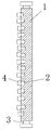
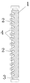
CN203275693U (en) Light guide plate with holes, and stereo assembly formed by same
CN202204949U (en) Two-in-one light guide plate and illuminating lamp of the same
CN104121516A (en) Lamp holder for table lamp and table lamp
CN203176827U (en) Transparent tablet lamp and light-emitting device provided with mirror
CN202253389U (en) Jigsaw-type three-dimensional light guide plate and lighting lamp
CN201892757U (en) Engraving and printing two-in-one light guide plate and illuminating lamp
CN203836856U (en) Light guide plate assembly and LED panel light
CN102537867A (en) Multi-step injection molding light guide plate and manufacture method thereof as well as illumination lamp
CN202217084U (en) Light guide plate and lighting fixture therewith
RU2398679C2 (en) Method of fabricating art and decorative panels (versions)
CN202501389U (en) Light guide plate with light guide points on both sides and lighting fixture
CN201837735U (en) Displayer and light guide plate with patterns carved on surface
CN101950042A (en) Light-guiding plate made by using offset printing method and making method thereof
JP2008218223A (en) Surface emitting apparatus
CN202305873U (en) Staggered light guide plate and lighting lamp
CN202361274U (en) Light guide plate having three-dimensional lighting effects and lighting lamp
CN102289029A (en) Two-in-one light guide plate and manufacturing method thereof as well as lighting lamp
KR20070101656A (en) Transparent plastic light guide panel and illumination apparatus with light guide panel
CN201836815U (en) Jigsaw light guide plate
CN102508330B (en) Dislocation light guide plate, manufacturing method thereof and illuminating lamp

Legal Events

Date Code Title Description
C14 Grant of patent or utility model
GR01 Patent grant
CP03 Change of name, title or address

Address after: No. 3 lanpuyuan industrial area Longgang street Longgang Road community Baolong Baolong four district of Shenzhen City, Guangdong province 518000 No. 1 building A601

Patentee after: Shenzhen onwing Au Optronics Co

Address before: 518000, four floor, five Asia Industrial Park, Bantian, Longgang District, Guangdong, Shenzhen

Patentee before: Shenzhen Onwing Optoelectronics Products Co., Ltd.

CP03 Change of name, title or address
TR01 Transfer of patent right

Effective date of registration: 20190624

Address after: 511400 No. 123, 3rd floor, 88 Qinghe Middle Road, Shiqiaojie, Panyu District, Guangzhou, Guangdong Province

Patentee after: Yuanbangjin Science and Technology Research Center (Guangzhou) Co., Ltd.

Address before: 518000 Workshop A601, No. 1, Lampuyuan Industrial Plant, No. 3 Baolong Road, Baolong Community, Longgang Street, Shenzhen City, Guangdong Province

Patentee before: Shenzhen onwing Au Optronics Co

TR01 Transfer of patent right
CF01 Termination of patent right due to non-payment of annual fee

Granted publication date: 20131106

Termination date: 20200402

CF01 Termination of patent right due to non-payment of annual fee