CN203274642U - Plug gauge assembly measuring diameter of inner annular groove of small hole - Google Patents
Plug gauge assembly measuring diameter of inner annular groove of small hole Download PDFInfo
- Publication number
- CN203274642U CN203274642U CN201320234167.5U CN201320234167U CN203274642U CN 203274642 U CN203274642 U CN 203274642U CN 201320234167 U CN201320234167 U CN 201320234167U CN 203274642 U CN203274642 U CN 203274642U
- Authority
- CN
- China
- Prior art keywords
- gauge
- plug gauge
- small hole
- measuring
- diameter
- Prior art date
- Legal status (The legal status is an assumption and is not a legal conclusion. Google has not performed a legal analysis and makes no representation as to the accuracy of the status listed.)
- Expired - Fee Related
Links
- 238000005259 measurement Methods 0.000 abstract description 13
- 238000001514 detection method Methods 0.000 abstract description 7
- 238000004519 manufacturing process Methods 0.000 abstract description 2
- 238000012545 processing Methods 0.000 description 4
- 238000010586 diagram Methods 0.000 description 3
- 238000000034 method Methods 0.000 description 3
- 238000012360 testing method Methods 0.000 description 3
- 238000003754 machining Methods 0.000 description 2
- 238000000691 measurement method Methods 0.000 description 1
Images

Classifications
-
- Y—GENERAL TAGGING OF NEW TECHNOLOGICAL DEVELOPMENTS; GENERAL TAGGING OF CROSS-SECTIONAL TECHNOLOGIES SPANNING OVER SEVERAL SECTIONS OF THE IPC; TECHNICAL SUBJECTS COVERED BY FORMER USPC CROSS-REFERENCE ART COLLECTIONS [XRACs] AND DIGESTS
- Y02—TECHNOLOGIES OR APPLICATIONS FOR MITIGATION OR ADAPTATION AGAINST CLIMATE CHANGE
- Y02E—REDUCTION OF GREENHOUSE GAS [GHG] EMISSIONS, RELATED TO ENERGY GENERATION, TRANSMISSION OR DISTRIBUTION
- Y02E30/00—Energy generation of nuclear origin
- Y02E30/30—Nuclear fission reactors
Landscapes
- Length-Measuring Instruments Using Mechanical Means (AREA)
- A Measuring Device Byusing Mechanical Method (AREA)
Abstract
一种测量小孔内环槽直径的塞规组件,用于解决提高小孔内环槽检测准确性、简化检测操作问题。其技术方案是:它由导向柱和塞规组成,所述导向柱外径与被测量小孔内径匹配,导向柱上设有偏心定位孔;所述塞规包括结构相同的通规和止规,所述塞规由下部定位销、中部测量体和上部操作手柄组成,通规、止规的测量体的公差尺寸不同,所述塞规的测量体外形为一侧被切割为轴向平面的圆柱体,所述定位销与偏心定位孔匹配插合。本实用新型结构简单,制造方便,操作容易,降低了测量难度,节省测量时间,提高工作效率,测量结果准确、可靠、不受人为因素影响。

A plug gauge assembly for measuring the diameter of an inner ring groove in a small hole, which is used to solve the problems of improving the detection accuracy of the inner ring groove in a small hole and simplifying the detection operation. The technical solution is: it is composed of a guide column and a plug gauge, the outer diameter of the guide column matches the inner diameter of the small hole to be measured, and an eccentric positioning hole is provided on the guide column; the plug gauge includes a through gauge and a stop gauge with the same structure , the plug gauge is composed of a lower positioning pin, a middle measuring body and an upper operating handle. The tolerances of the measuring bodies of the through gauge and the stop gauge are different. The shape of the measuring body of the plug gauge is that one side is cut into an axial plane A cylinder, the positioning pin is mated with the eccentric positioning hole. The utility model has the advantages of simple structure, convenient manufacture, easy operation, reduced measurement difficulty, saved measurement time, improved work efficiency, accurate and reliable measurement results, and is not affected by human factors.
Description
技术领域 technical field
本实用新型涉及一种机械加工零件检测量具,特别是用于测量小孔内环槽直径的塞规组件。 The utility model relates to a measuring instrument for machining parts, in particular to a plug gauge assembly for measuring the diameter of an inner ring groove in a small hole.
背景技术 Background technique
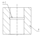
在机械加工领域,经常会遇到如图5 所示带有内环槽4-1的小直径内孔工件4,加工这种工件的内环槽部位需要对其精度进行测量。目前常用的测量方法如下:1.卡钳测量,测量操作的准确性受人为因素影响,检测准确度与测量人员的经验密切相关;2.采用卡规测量,虽测量准确性高但所用量具价格高;3.间接测量,测量刀具,通过在加工前测量加工内环槽用刀具的尺寸,来保证内环槽的直径尺寸,该方法加工设备、刀具磨损、加工参数等因素对内环槽直径的影响不能准确计算出,测量准确度低。 In the field of mechanical processing, it is often encountered a small-diameter inner hole workpiece 4 with an inner ring groove 4-1 as shown in Figure 5, and the accuracy of the inner ring groove of this workpiece needs to be measured. At present, the commonly used measurement methods are as follows: 1. Caliper measurement, the accuracy of measurement operation is affected by human factors, and the detection accuracy is closely related to the experience of the measurement personnel; 2. Using caliper measurement, although the measurement accuracy is high, the price of the measuring tools used is high ; 3. Indirect measurement, measuring tool, by measuring the size of the tool for machining the inner ring groove before processing, to ensure the diameter of the inner ring groove, the method processing equipment, tool wear, processing parameters and other factors affect the diameter of the inner ring groove The impact cannot be accurately calculated and the measurement accuracy is low.
实用新型内容 Utility model content
本实用新型的目的在于针对现有技术之弊端,提供一种检测手段简单易行、检测结果可靠性高、不受外界因素干扰的的测量小孔内环槽直径的塞规。 The purpose of the utility model is to aim at the disadvantages of the prior art, and provide a plug gauge for measuring the diameter of the ring groove in a small hole, which has simple and easy detection means, high reliability of the detection results, and is not disturbed by external factors.
本实用新型所述问题是以下述技术方案实现的: Problem described in the utility model is realized with following technical scheme:
一种测量小孔内环槽直径的塞规组件,特别之处是,它由导向柱和塞规组成,所述导向柱外径与被测量小孔内径匹配,导向柱上设有偏心定位孔;所述塞规包括结构相同的通规和止规,所述塞规由下部定位销、中部测量体和上部操作手柄组成,通规、止规的测量体的公差尺寸不同,所述塞规的测量体外形为一侧被切割为轴向平面的圆柱体,所述定位销与偏心定位孔匹配插合。 A plug gauge assembly for measuring the diameter of the inner ring groove of a small hole. In particular, it is composed of a guide post and a plug gauge. The outer diameter of the guide post matches the inner diameter of the small hole to be measured, and an eccentric positioning hole is arranged on the guide post. ; The plug gauge includes a pass gauge and a stop gauge with the same structure. The plug gauge is composed of a lower positioning pin, a middle measuring body and an upper operating handle. The tolerance sizes of the gauge and the stop gauge are different. The shape of the measuring body is a cylinder with one side cut into an axial plane, and the positioning pin is mated and inserted into the eccentric positioning hole.
上述测量小孔内环槽直径的塞规组件,所述塞规的操作手柄外形为一侧切割为轴向平面的圆柱体,操作手柄的轴向平面与测量体的轴向平面平行,操作手柄的轴向平面上设有识别标记。 For the above-mentioned plug gauge assembly for measuring the diameter of the inner ring groove of a small hole, the shape of the operating handle of the plug gauge is a cylinder with one side cut into an axial plane, the axial plane of the operating handle is parallel to the axial plane of the measuring body, and the operating handle There are identification marks on the axial plane.
上述测量小孔内环槽直径的塞规组件,所述导向柱下部沿径向设有限位螺纹孔,限位螺纹孔内设有与其匹配螺接的限位销。 For the above-mentioned plug gauge assembly for measuring the diameter of the inner ring groove in the small hole, the lower part of the guide column is provided with a limit threaded hole in the radial direction, and a limit pin matched with the threaded hole is provided in the limit threaded hole.
本实用新型针对提高小孔内环槽检测准确性、简化检测操作问题而设计了一种专用于测量小孔内环槽直径的塞规组件。所述塞规组件由导向柱和塞规组成,塞规包括通规和止规。采用本实用新型测量小孔内环槽尺寸,依次利用通规、止规测试,测量时将导向柱插入被测零件的内孔,再将塞规的定位销插入导向柱的偏心定位孔中,旋转操作手柄若通规通过内环槽的直径,止规不能通过,判定内环槽直径合格;若通规止规都通过,判定工件不合格;若通规无法通过,则判定工件不合格。本实用新型结构简单,制造方便,操作容易,降低了测量难度,节省测量时间,提高工作效率,测量结果准确、可靠、不受人为因素影响。 The utility model designs a plug gauge component specially used for measuring the diameter of the inner ring groove in the small hole aiming at improving the detection accuracy of the ring groove in the small hole and simplifying the detection operation. The plug gauge assembly is composed of a guide column and a plug gauge, and the plug gauge includes a through gauge and a stop gauge. The utility model is used to measure the size of the inner ring groove of the small hole, and the through gauge and the stop gauge are used to test in sequence. When measuring, the guide column is inserted into the inner hole of the part to be tested, and then the positioning pin of the plug gauge is inserted into the eccentric positioning hole of the guide column. Rotate the operating handle, if the through gauge passes the diameter of the inner ring groove, but the stop gauge cannot pass, then the diameter of the inner ring groove is determined to be qualified; if both the through gauge and the stop gauge pass, it is determined that the workpiece is unqualified; The utility model has the advantages of simple structure, convenient manufacture, easy operation, reduced measurement difficulty, saved measurement time, improved work efficiency, accurate and reliable measurement results, and is not affected by human factors.
附图说明 Description of drawings
下面结合附图对本实用新型作进一步说明。 Below in conjunction with accompanying drawing, the utility model is further described.
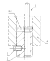
图1是本实用新型测量状态结构示意图; Fig. 1 is a schematic diagram of the utility model measuring state structure;
图2是导向柱的结构示意图; Fig. 2 is the structural representation of guide column;
图3是塞规结构示意图; Fig. 3 is a schematic diagram of plug gauge structure;
图4是图3的俯视图; Fig. 4 is the top view of Fig. 3;
图5是小孔内环槽工件的结构示意图。 Fig. 5 is a schematic diagram of the structure of the small hole inner ring groove workpiece.
图中各标号清单为:1、限位销,2、导向柱,2-1、偏心定位孔,2-2、限位螺纹孔, 3、塞规,3-1、操作手柄,3-2、操作手柄的轴向平面,3-3、测量体,3-4、测量体的轴向平面,3-5、定位销,4、小孔内环槽工件,4-1、内环槽。 The list of labels in the figure is: 1. Limit pin, 2. Guide post, 2-1, Eccentric positioning hole, 2-2, Limit screw hole, 3. Plug gauge, 3-1, Operating handle, 3-2 , the axial plane of the operating handle, 3-3, the measuring body, 3-4, the axial plane of the measuring body, 3-5, the positioning pin, 4, the small hole inner ring groove workpiece, 4-1, the inner ring groove.
具体实施方式 Detailed ways
参看图1、图2,本实用新型由导向柱2和塞规3组成。所述导向柱2的外径与被测小孔内环槽工件4的小孔内径匹配插合,导向柱上设有偏心定位孔2-1,导向柱下部沿径向设有限位螺纹孔2-2,限位螺纹孔内设有与其匹配螺接的限位销1,测量时限位销与小孔内环槽工件4的端面靠紧,对导向柱起到轴向限位作用。
Referring to Fig. 1, Fig. 2, the utility model is made up of
参看图3、图4,所述塞规3包括结构相同通规和止规,塞规由下部定位销3-5、中部测量体3-3和上部操作手柄3-1组成,通规、止规测量体的基本尺寸相同、上下偏差尺寸不同,其中,通规测量体的尺寸依据被测内环槽的最小极限尺寸设计,止规测量体的尺寸依据被测内环槽的最大极限尺寸设计。所述塞规的测量体外形为一侧被切割为轴向平面的圆柱体。所述定位销3-5与偏心定位孔2-1匹配插合。塞规的操作手柄3-1外形为一侧切割为轴向平面的圆柱体,操作手柄的轴向平面3-2与测量体的轴向平面3-4平行。操作手柄的轴向平面3-2一方面用于刻图号和识别标记(通规上的标记为T,止规上的标记为Z),另一方面便于在塞规插合时识别方向。 Referring to Fig. 3 and Fig. 4, the plug gauge 3 includes a through gauge and a stop gauge with the same structure. The plug gauge is composed of a lower positioning pin 3-5, a middle measuring body 3-3 and an upper operating handle 3-1. The basic size of the measuring body of the gauge is the same, and the upper and lower deviation sizes are different. The size of the measuring body of the through gauge is designed according to the minimum limit size of the inner ring groove under test, and the size of the measuring body of the stop gauge is designed according to the maximum limit size of the inner ring groove under test. . The shape of the measuring body of the plug gauge is a cylinder with one side cut into an axial plane. The positioning pin 3-5 is mated with the eccentric positioning hole 2-1. The shape of the operating handle 3-1 of the plug gauge is a cylinder with one side cut into an axial plane, and the axial plane 3-2 of the operating handle is parallel to the axial plane 3-4 of the measuring body. On the one hand, the axial plane 3-2 of the operating handle is used for engraving numbers and identification marks (the mark on the through gauge is T, and the mark on the stop gauge is Z), and on the other hand, it is convenient for identifying the direction when the plug gauge is inserted.
参看图1,本实用新型使用时,将导向柱2插入小孔内环槽工件4的内孔中,使限位销1靠紧工件端面;将塞规3的操作手柄的轴向平面3-2近距离对应被测内环槽4-1的孔壁,将定位销3-5插入导向柱的偏心定位孔内,旋转操作手柄;依次按照上述步骤取通规、止规操作,若通规在旋转过程中可通过内环槽直径,且止规不能通过,判定工件合格;若通规、止规在旋转过程中都可以通过内环槽直径,判定工件不合格;若通规在旋转过程中无法通过内环槽直径,则判定工件不合格。
Referring to Fig. 1, when the utility model is used, the
Claims (3)
Priority Applications (1)
| Application Number | Priority Date | Filing Date | Title |
|---|---|---|---|
| CN201320234167.5U CN203274642U (en) | 2013-05-03 | 2013-05-03 | Plug gauge assembly measuring diameter of inner annular groove of small hole |
Applications Claiming Priority (1)
| Application Number | Priority Date | Filing Date | Title |
|---|---|---|---|
| CN201320234167.5U CN203274642U (en) | 2013-05-03 | 2013-05-03 | Plug gauge assembly measuring diameter of inner annular groove of small hole |
Publications (1)
| Publication Number | Publication Date |
|---|---|
| CN203274642U true CN203274642U (en) | 2013-11-06 |
Family
ID=49505030
Family Applications (1)
| Application Number | Title | Priority Date | Filing Date |
|---|---|---|---|
| CN201320234167.5U Expired - Fee Related CN203274642U (en) | 2013-05-03 | 2013-05-03 | Plug gauge assembly measuring diameter of inner annular groove of small hole |
Country Status (1)
| Country | Link |
|---|---|
| CN (1) | CN203274642U (en) |
Cited By (5)
| Publication number | Priority date | Publication date | Assignee | Title |
|---|---|---|---|---|
| CN109341479A (en) * | 2018-11-20 | 2019-02-15 | 中国航发贵州黎阳航空动力有限公司 | A kind of annular groove step for nozzle body parts measurement refers to that mould is advised |
| CN109596026A (en) * | 2018-11-30 | 2019-04-09 | 瓦房店轴承集团国家轴承工程技术研究中心有限公司 | Bearing retainer pocket hole inspection method and hole inspection |
| CN110333247A (en) * | 2019-06-06 | 2019-10-15 | 惠尔信机械(泰兴)有限公司 | The rope sheave accuracy checking method of elevator traction machine |
| CN113237402A (en) * | 2021-01-09 | 2021-08-10 | 广西玉柴机器股份有限公司 | Checking and measuring tool for positioning pin hole of thrust plate of thrust baffle shaft cover and using method |
| CN113909999A (en) * | 2021-10-19 | 2022-01-11 | 西安长峰机电研究所 | Method for machining and detecting end surface deep annular groove |
-
2013
- 2013-05-03 CN CN201320234167.5U patent/CN203274642U/en not_active Expired - Fee Related
Cited By (7)
| Publication number | Priority date | Publication date | Assignee | Title |
|---|---|---|---|---|
| CN109341479A (en) * | 2018-11-20 | 2019-02-15 | 中国航发贵州黎阳航空动力有限公司 | A kind of annular groove step for nozzle body parts measurement refers to that mould is advised |
| CN109596026A (en) * | 2018-11-30 | 2019-04-09 | 瓦房店轴承集团国家轴承工程技术研究中心有限公司 | Bearing retainer pocket hole inspection method and hole inspection |
| CN109596026B (en) * | 2018-11-30 | 2020-09-22 | 瓦房店轴承集团国家轴承工程技术研究中心有限公司 | Bearing cage pocket detection method |
| CN110333247A (en) * | 2019-06-06 | 2019-10-15 | 惠尔信机械(泰兴)有限公司 | The rope sheave accuracy checking method of elevator traction machine |
| CN110333247B (en) * | 2019-06-06 | 2021-12-24 | 惠尔信机械(泰兴)有限公司 | Rope wheel precision detection method of elevator traction machine |
| CN113237402A (en) * | 2021-01-09 | 2021-08-10 | 广西玉柴机器股份有限公司 | Checking and measuring tool for positioning pin hole of thrust plate of thrust baffle shaft cover and using method |
| CN113909999A (en) * | 2021-10-19 | 2022-01-11 | 西安长峰机电研究所 | Method for machining and detecting end surface deep annular groove |
Similar Documents
| Publication | Publication Date | Title |
|---|---|---|
| CN203274642U (en) | Plug gauge assembly measuring diameter of inner annular groove of small hole | |
| CN201392162Y (en) | A tool for detecting the position degree of teeth or tooth grooves on a gear shaft | |
| CN204240934U (en) | A kind of right alignment detects servicing unit | |
| CN202092543U (en) | Pump casing position detecting fixture | |
| CN103486943A (en) | Taper hole depth detecting device | |
| CN107990803A (en) | Screw hole system position detection device | |
| CN203811070U (en) | Comprehensive inspection tool of bearing cap | |
| CN105371722A (en) | Checking tool capable of measuring 0.7-dimension end surface teeth | |
| CN103063113A (en) | Detecting jig for semiround workpiece | |
| CN202661020U (en) | Tool used for measuring depth of conical hole in deep hole | |
| CN204730792U (en) | A kind of hand-held internal diameter guide rail conical surface measurement mechanism | |
| CN103344167A (en) | Crankshaft semicircular key groove depth detection tool | |
| CN202734708U (en) | Tool for rapid detection of screwed holes | |
| CN201787874U (en) | Measuring tool for detecting small diameter of external thread | |
| CN203758432U (en) | Depth detection device of screw hole | |
| CN103307952A (en) | Measuring instrument for diameter of lever-type deep hole | |
| CN204255244U (en) | A kind of device measuring coating thickness | |
| CN202885737U (en) | Depth gauge with degree scale | |
| CN203758442U (en) | Step deep hole coaxiality gauge | |
| CN102962729B (en) | Method for realizing on-line measurement of multi-purpose measuring head for vertical numerically controlled lathe | |
| CN203672279U (en) | Testing tool for detecting gear inner bore diameter | |
| CN202885738U (en) | Simple deep touch gauge | |
| CN106197217B (en) | A kind of accurate detection device of bearing ring outer-diameter accuracy | |
| CN203037185U (en) | Detecting jig for semicircular workpiece | |
| CN102927888A (en) | Simple depth touch gauge |
Legal Events
| Date | Code | Title | Description |
|---|---|---|---|
| C14 | Grant of patent or utility model | ||
| GR01 | Patent grant | ||
| CF01 | Termination of patent right due to non-payment of annual fee |
Granted publication date: 20131106 Termination date: 20200503 |
|
| CF01 | Termination of patent right due to non-payment of annual fee |