CN203273720U - Laser lamp with protective cover - Google Patents
Laser lamp with protective cover Download PDFInfo
- Publication number
- CN203273720U CN203273720U CN201320337484XU CN201320337484U CN203273720U CN 203273720 U CN203273720 U CN 203273720U CN 201320337484X U CN201320337484X U CN 201320337484XU CN 201320337484 U CN201320337484 U CN 201320337484U CN 203273720 U CN203273720 U CN 203273720U
- Authority
- CN
- China
- Prior art keywords
- laser lamp
- main body
- cover
- protective cover
- laser
- Prior art date
- Legal status (The legal status is an assumption and is not a legal conclusion. Google has not performed a legal analysis and makes no representation as to the accuracy of the status listed.)
- Expired - Fee Related
Links
Images


Landscapes
- Non-Portable Lighting Devices Or Systems Thereof (AREA)
Abstract
本实用新型涉及激光灯技术领域,更具体地,涉及一种护盖激光灯,包括激光灯主体,所述激光灯主体外部设有至少遮挡激光灯主体顶部的护盖。本实用新型护盖激光灯在激光灯主体的外部加设护盖,护盖至少能遮挡激光灯主体的顶部,护盖具有防水、防尘、防腐等防护功能,保护了激光灯,当激光灯在户外使用时,能够避免日晒雨淋,使用寿命延长。
The utility model relates to the technical field of laser lamps, in particular to a laser lamp with a protective cover, which includes a main body of the laser lamp, and a protective cover that at least blocks the top of the main body of the laser lamp is provided outside the main body of the laser lamp. The protective cover laser lamp of the utility model is equipped with a protective cover outside the main body of the laser lamp. The protective cover can at least cover the top of the main body of the laser lamp. When used outdoors, it can avoid the sun and rain and prolong the service life.
Description
技术领域 technical field
本实用新型涉及激光灯技术领域,更具体地,涉及一种护盖激光灯。 The utility model relates to the technical field of laser lamps, in particular to a cover laser lamp.
背景技术 Background technique
激光灯的灯光具有颜色鲜艳、亮度高、指向性好、射程远、易控制等优点,看上去更具神奇梦幻的感觉,常应用在大楼、公园、广场、剧场等,利用激光光束的不发散性,能吸引远至几公里外人们的目光,因从激光发出点也成了人们关注的焦点。目前的激光灯通常用于室内,由于室外的条件变化不稳定,很难保证激光灯的使用寿命,现也有部分激光灯用于室外,但由于毫无保护措施,使用寿命短。 The light of laser lights has the advantages of bright colors, high brightness, good directivity, long range, and easy control. It looks more magical and dreamy. It is often used in buildings, parks, squares, theaters, etc. It can attract the attention of people as far as several kilometers away, because the point where the laser is emitted has also become the focus of people's attention. The current laser lights are usually used indoors. Due to the unstable outdoor conditions, it is difficult to guarantee the service life of the laser lights. Now some laser lights are used outdoors, but due to no protective measures, the service life is short.
实用新型内容 Utility model content
本实用新型为克服上述现有技术所述的至少一种缺陷,提供一种护盖激光灯,在激光灯主体外部加设具有防水、防尘、防腐等作用的护盖,保护激光灯,延长使用寿命。 In order to overcome at least one defect of the above-mentioned prior art, the utility model provides a laser lamp with a protective cover. A protective cover with waterproof, dustproof, anti-corrosion and other functions is added outside the main body of the laser lamp to protect the laser lamp and prolong the life of the laser lamp. service life.
为解决上述技术问题,本实用新型采用的技术方案是: In order to solve the problems of the technologies described above, the technical solution adopted in the utility model is:
提供一种护盖激光灯,包括激光灯主体,所述激光灯主体外部设有至少遮挡激光灯主体顶部的护盖。本实用新型护盖激光灯在激光灯主体的外部加设护盖,护盖至少能遮挡激光灯主体的顶部,护盖具有防水、防尘、防腐等防护功能,保护了激光灯,当激光灯在户外使用时,能够避免日晒雨淋,使用寿命延长。 Provided is a laser lamp with a cover, which includes a laser lamp main body, and a protective cover that at least blocks the top of the laser lamp main body is provided outside the laser lamp main body. The protective cover laser lamp of the utility model is equipped with a protective cover outside the main body of the laser lamp. The protective cover can at least cover the top of the main body of the laser lamp. When used outdoors, it can avoid the sun and rain and prolong the service life.
可选地,所述护盖包括上盖以及侧壁,所述侧壁在激光灯主体出光处的对应位置上设有通孔。除了在设置上盖遮挡激光灯主体,为了达到更好的保护效果,在激光灯主体的四周也加设防护,即增加了上盖往下延伸围绕激光灯主体设置的侧壁。 Optionally, the protective cover includes an upper cover and a side wall, and the side wall is provided with a through hole at a position corresponding to the light output of the main body of the laser lamp. In addition to setting the upper cover to cover the main body of the laser light, in order to achieve a better protection effect, protection is also added around the main body of the laser light, that is, the upper cover is extended downward to surround the side wall of the main body of the laser light.
优选地,所述通孔处设有玻璃盖。玻璃盖可供激光灯穿过照射,该设计既不影响激光灯的正常使用,又能防护激光灯主体,简单实用。 Preferably, a glass cover is provided at the through hole. The glass cover allows the laser light to pass through and irradiate. This design does not affect the normal use of the laser light and protects the main body of the laser light. It is simple and practical.
进一步地,本方案的护盖激光灯还包括支架,所述支架包括底盘、设于底盘上的第一支撑件以及第二支撑件,所述第一支撑件和第二支撑件分别与激光灯主体的两侧转动连接。该结构设计使激光灯主体在支架的支撑作用下,在同一个位置即可实现不同方向的照射,使用简单方便。 Further, the cover laser lamp of this solution also includes a bracket, and the bracket includes a chassis, a first support and a second support arranged on the chassis, and the first support and the second support are respectively connected to the laser lamp. Both sides of the main body are rotationally connected. This structural design enables the main body of the laser light to be irradiated in different directions at the same position under the support of the bracket, which is simple and convenient to use.
更进一步地,所述护盖两侧设有转动结构,所述转动结构设于激光灯主体两侧分别与第一支撑件和第二支撑件转动连接处。由于激光灯主体与支架转动连接,在护盖的两侧设置转动结构,使护盖可随激光灯主体旋转,起到防护的作用。 Furthermore, a rotating structure is provided on both sides of the protective cover, and the rotating structure is provided at the places where both sides of the main body of the laser lamp are respectively connected to the first support and the second support in rotation. Since the main body of the laser light is connected to the bracket in rotation, a rotating structure is provided on both sides of the protective cover, so that the protective cover can rotate with the main body of the laser light to play a protective role.
与现有技术相比,本实用新型的有益效果是: Compared with the prior art, the beneficial effects of the utility model are:
本实用新型护盖激光灯在激光灯主体的外部加设护盖,护盖至少能遮挡激光灯主体的顶部,护盖具有防水、防尘、防腐等防护功能,保护了激光灯,当激光灯在户外使用时,能够避免日晒雨淋,使用寿命延长。 The protective cover laser lamp of the utility model is equipped with a protective cover outside the main body of the laser lamp. The protective cover can at least cover the top of the main body of the laser lamp. When used outdoors, it can avoid the sun and rain and prolong the service life.
附图说明 Description of drawings
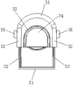
图1为本实用新型实施例护盖激光灯的结构示意图。 Fig. 1 is a schematic structural diagram of a cover laser lamp according to an embodiment of the present invention.
图2为图1的主视图。 Fig. 2 is a front view of Fig. 1 .
图3为本实用新型实施例护盖激光灯取下护盖后的结构示意图。 Fig. 3 is a schematic structural view of the protective cover laser lamp of the embodiment of the present invention after the protective cover is removed.
图4为护盖的结构示意图。 Fig. 4 is a schematic structural diagram of the protective cover.
具体实施方式 Detailed ways
下面结合具体实施方式对本实用新型作进一步的说明。其中,附图仅用于示例性说明,表示的仅是示意图,而非实物图,不能理解为对本专利的限制;为了更好地说明本实用新型的实施例,附图某些部件会有省略、放大或缩小,并不代表实际产品的尺寸;对本领域技术人员来说,附图中某些公知结构及其说明可能省略是可以理解的。 The utility model will be further described below in conjunction with specific embodiments. Wherein, the accompanying drawings are for illustrative purposes only, and represent only schematic diagrams, rather than actual drawings, and should not be construed as limitations on this patent; in order to better illustrate the embodiments of the present utility model, some parts of the accompanying drawings will be omitted , enlargement or reduction, and do not represent the size of the actual product; for those skilled in the art, it is understandable that some known structures and their descriptions in the drawings may be omitted.
如图1至图2所示为本实用新型护盖激光灯的实施例,如图1所示,包括激光灯主体10以及支架20,激光灯主体10外部设有遮挡激光灯主体10顶部及四周的护盖30。本实施例中,如图2所示,护盖30包括上盖31以及侧壁32,侧壁32在激光灯主体10出光处的对应位置上设有通孔33,通孔33处设有玻璃盖34,玻璃盖34可供激光灯穿过照射。
As shown in Figures 1 to 2, the embodiment of the laser lamp with a protective cover of the present invention, as shown in Figure 1, includes a laser lamp
如图2所示,支架20包括底盘21、设于底盘21上的第一支撑件22以及第二支撑件23,第一支撑件22和第二支撑件23分别与激光灯主体10的两侧转动连接;护盖30两侧设有转动结构35,转动结构35设于激光灯主体10两侧分别与第一支撑件22和第二支撑件23转动连接处。该结构设计使激光灯主体10在支架20的支撑作用下,在同一个位置即可实现不同方向的照射,使用简单方便;由于激光灯主体10与支架20转动连接,在护盖30的两侧设置转动结构35,使护盖30可随激光灯主体10旋转,起到防护的作用。
As shown in Figure 2, the
本实施例护盖激光灯在激光灯主体10的外部加设护盖30,护盖30能遮挡激光灯主体10的顶部及四周,护盖30具有防水、防尘、防腐等防护功能,保护了激光灯,当激光灯在户外使用时,能够避免日晒雨淋,使用寿命延长。
In this embodiment, the protective cover laser lamp is equipped with a
显然,本实用新型的上述实施例仅仅是为清楚地说明本实用新型所作的举例,而并非是对本实用新型的实施方式的限定。对于所属领域的普通技术人员来说,在上述说明的基础上还可以做出其它不同形式的变化或变动。这里无需也无法对所有的实施方式予以穷举。凡在本实用新型的精神和原则之内所作的任何修改、等同替换和改进等,均应包含在本实用新型权利要求的保护范围之内。 Apparently, the above-mentioned embodiments of the present utility model are only examples for clearly illustrating the present utility model, rather than limiting the implementation manner of the present utility model. For those of ordinary skill in the art, other changes or changes in different forms can be made on the basis of the above description. It is not necessary and impossible to exhaustively list all the implementation manners here. All modifications, equivalent replacements and improvements made within the spirit and principles of the utility model shall be included in the protection scope of the claims of the utility model.
Claims (5)
Priority Applications (1)
| Application Number | Priority Date | Filing Date | Title |
|---|---|---|---|
| CN201320337484XU CN203273720U (en) | 2013-06-13 | 2013-06-13 | Laser lamp with protective cover |
Applications Claiming Priority (1)
| Application Number | Priority Date | Filing Date | Title |
|---|---|---|---|
| CN201320337484XU CN203273720U (en) | 2013-06-13 | 2013-06-13 | Laser lamp with protective cover |
Publications (1)
| Publication Number | Publication Date |
|---|---|
| CN203273720U true CN203273720U (en) | 2013-11-06 |
Family
ID=49504121
Family Applications (1)
| Application Number | Title | Priority Date | Filing Date |
|---|---|---|---|
| CN201320337484XU Expired - Fee Related CN203273720U (en) | 2013-06-13 | 2013-06-13 | Laser lamp with protective cover |
Country Status (1)
| Country | Link |
|---|---|
| CN (1) | CN203273720U (en) |
Cited By (10)
| Publication number | Priority date | Publication date | Assignee | Title |
|---|---|---|---|---|
| CN104061499A (en) * | 2014-07-15 | 2014-09-24 | 徐志亮 | Laser lamp |
| US9752761B2 (en) | 2014-07-16 | 2017-09-05 | Telebrands Corp. | Landscape light |
| USD797975S1 (en) | 2016-09-29 | 2017-09-19 | Telebrands Corp. | Landscape light |
| USD798484S1 (en) | 2016-09-29 | 2017-09-26 | Telebrands Corp. | Landscape light |
| USD804083S1 (en) | 2014-10-30 | 2017-11-28 | Telebrands Corp. | Landscape light |
| US9879847B2 (en) | 2015-12-03 | 2018-01-30 | Telebrands Corp. | Decorative lighting apparatus having two laser light sources |
| USD816890S1 (en) | 2015-05-11 | 2018-05-01 | Telebrands Corp. | Light projector |
| USD820507S1 (en) | 2015-05-11 | 2018-06-12 | Telebrands Corp. | Light projector |
| USD824066S1 (en) | 2015-05-11 | 2018-07-24 | Telebrands Corp. | Light projector |
| USD828619S1 (en) | 2015-05-11 | 2018-09-11 | Telebrands Corp. | Light projector |
-
2013
- 2013-06-13 CN CN201320337484XU patent/CN203273720U/en not_active Expired - Fee Related
Cited By (17)
| Publication number | Priority date | Publication date | Assignee | Title |
|---|---|---|---|---|
| CN104061499A (en) * | 2014-07-15 | 2014-09-24 | 徐志亮 | Laser lamp |
| US9752761B2 (en) | 2014-07-16 | 2017-09-05 | Telebrands Corp. | Landscape light |
| US10228113B2 (en) | 2014-07-16 | 2019-03-12 | Telebrands Corp. | Landscape light |
| US10197234B2 (en) | 2014-07-16 | 2019-02-05 | Telebrands Corp. | Landscape light |
| US9869459B2 (en) | 2014-07-16 | 2018-01-16 | Telebrands Corp. | Landscape light |
| US9874327B2 (en) | 2014-07-16 | 2018-01-23 | Telebrands Corp. | Landscape light |
| USD804083S1 (en) | 2014-10-30 | 2017-11-28 | Telebrands Corp. | Landscape light |
| USD804715S1 (en) | 2014-10-30 | 2017-12-05 | Telebrands Corp. | Landscape light |
| USD824066S1 (en) | 2015-05-11 | 2018-07-24 | Telebrands Corp. | Light projector |
| USD816890S1 (en) | 2015-05-11 | 2018-05-01 | Telebrands Corp. | Light projector |
| USD820507S1 (en) | 2015-05-11 | 2018-06-12 | Telebrands Corp. | Light projector |
| USD821023S1 (en) | 2015-05-11 | 2018-06-19 | Telebrands Corp. | Light projector |
| USD828619S1 (en) | 2015-05-11 | 2018-09-11 | Telebrands Corp. | Light projector |
| USD828618S1 (en) | 2015-05-11 | 2018-09-11 | Telebrands Corp. | Light projector |
| US9879847B2 (en) | 2015-12-03 | 2018-01-30 | Telebrands Corp. | Decorative lighting apparatus having two laser light sources |
| USD798484S1 (en) | 2016-09-29 | 2017-09-26 | Telebrands Corp. | Landscape light |
| USD797975S1 (en) | 2016-09-29 | 2017-09-19 | Telebrands Corp. | Landscape light |
Similar Documents
| Publication | Publication Date | Title |
|---|---|---|
| CN206429994U (en) | It is a kind of can folding outdoor garden lamp | |
| CN202835153U (en) | Multifunctional outdoor projection street lamp | |
| CN207975583U (en) | A kind of LED stage lamp with ornamental value | |
| CN204614149U (en) | A smoke alarm based on garden energy-saving street lamps | |
| CN202629897U (en) | Solar lawn lamp with lawn care alerter | |
| CN201902974U (en) | Flexible solar street lamp | |
| CN204853304U (en) | A multifunctional street light | |
| CN205135101U (en) | Gardens rail guard | |
| CN202327936U (en) | Novel garden lamp | |
| CN205790328U (en) | Illumination type communication support | |
| CN201547623U (en) | Universal ceiling light | |
| CN204127761U (en) | A kind of LED flood light | |
| CN204387887U (en) | Landscape lamp | |
| CN203202826U (en) | Lawn lamp | |
| CN206419775U (en) | A collapsible spotlight | |
| CN206338665U (en) | A kind of road illumination device | |
| CN205177087U (en) | High pressure warning device | |
| CN203273300U (en) | Electrician head lamp with two lamp caps | |
| CN205208342U (en) | Street lamp for municipal works | |
| CN206540030U (en) | A smart windmill light | |
| CN201834687U (en) | Double-beam bridge type crane beam sound and light control automatic lighting system | |
| CN206419842U (en) | A High Mast Light with Reduced Wind Resistance | |
| CN206504225U (en) | A kind of street lamp of convex lens | |
| CN209341090U (en) | An angle-adjustable floodlight with a charging device | |
| CN204534433U (en) | Lampshade for LED lights with shading and uniform light functions |
Legal Events
| Date | Code | Title | Description |
|---|---|---|---|
| C14 | Grant of patent or utility model | ||
| GR01 | Patent grant | ||
| C41 | Transfer of patent application or patent right or utility model | ||
| TR01 | Transfer of patent right |
Effective date of registration: 20151230 Address after: 518000 Guangdong province Shenzhen city Longhua District Zhao Xiang Fulong road building room 1401-1408 Patentee after: Shenzhen million Technology Co. Ltd. Address before: 518105 Guangdong city of Shenzhen province Baoan District Songgang street Luotian forest Qiaohua Industrial Zone No. 301 factory Patentee before: Shenzhen Quwha Industrial Co., Ltd. |
|
| CF01 | Termination of patent right due to non-payment of annual fee |
Granted publication date: 20131106 Termination date: 20190613 |
|
| CF01 | Termination of patent right due to non-payment of annual fee |