CN203250888U - Multiposition socket - Google Patents
Multiposition socket Download PDFInfo
- Publication number
- CN203250888U CN203250888U CN 201320247821 CN201320247821U CN203250888U CN 203250888 U CN203250888 U CN 203250888U CN 201320247821 CN201320247821 CN 201320247821 CN 201320247821 U CN201320247821 U CN 201320247821U CN 203250888 U CN203250888 U CN 203250888U
- Authority
- CN
- China
- Prior art keywords
- socket
- utmost point
- disjunctor
- conducting strip
- inlet wire
- Prior art date
- Legal status (The legal status is an assumption and is not a legal conclusion. Google has not performed a legal analysis and makes no representation as to the accuracy of the status listed.)
- Expired - Lifetime
Links
Images

Landscapes
- Details Of Connecting Devices For Male And Female Coupling (AREA)
Abstract
The utility model relates to a socket. The multiposition socket comprises a socket casing, an N electrode line incoming conductive sheet, an L electrode line incoming conductive sheet and at least six socket positions. Each socket position comprises an N electrode plug bush which is connected with the N electrode line incoming conductive sheet and an L electrode plug bush which is connected with the L electrode line incoming conductive sheet. Only one N electrode line incoming conductive sheet is arranged. Only one L electrode line incoming conductive sheet is arranged. The multiposition socket provided by the utility model has the advantages of compact structure and convenient production, and solves the problems of loose structure and inconvenient production of the existing multiposition socket with more than six socket positions.
Description
Technical field
The utility model relates to socket, relates in particular to a kind of multiposition socket.
Background technology
Can plug simultaneously several plugs in the socket then is referred to as several sockets and has in other words what socket positions (for by three pole sockets and the Universal Socket that two pole sockets consist of, although can be complementary with the plug of two kinds of specifications, but can only insert a plug in the same time, therefore also can only calculate a socket position).Be 2008201119041 in China Patent No., name is called in the patent document that " a kind of multiposition socket ", Granted publication day are on February 18th, 2002 and discloses a kind of multiposition socket with 3 socket positions.
The existing multiposition socket that has more than six socket positions all is that two N utmost point inlet wire conducting strips and two L utmost point inlet wire conducting strips are set in the socket shell, N utmost point sleeve in the part socket position links together with a slice N utmost point inlet wire conducting strip, L utmost point sleeve links together with a slice L utmost point inlet wire conducting strip, N utmost point sleeve in another part socket position links together with another sheet N utmost point inlet wire conducting strip, L utmost point sleeve links together with another sheet L utmost point inlet wire conducting strip, then introduces power supply to a slice N utmost point inlet wire conducting strip and a slice L utmost point inlet wire conducting strip by a power line, another root power line is introduced power supply to another sheet N utmost point inlet wire conducting strip and another sheet L utmost point inlet wire conducting strip.The existing connected mode of multiposition socket has the following disadvantages: structural compactness is poor, production and assembly inconvenience.
The utility model content
The utility model provides the multiposition socket that a kind of structural compactness is good, be convenient to produce, and has solved the existing problem that the multi-position socket construction compactedness is poor, production is inconvenient with six above socket positions.
Above technical problem solves by following technical proposal: a kind of multiposition socket, comprise socket shell, N utmost point inlet wire conducting strip, L utmost point inlet wire conducting strip and at least six socket positions, each described socket position comprises the N utmost point sleeve and the L utmost point sleeve that links together with L utmost point inlet wire conducting strip that link together with N utmost point inlet wire conducting strip, described N utmost point inlet wire conducting strip only has a slice, and described L utmost point inlet wire conducting strip only has a slice.If the socket position is for the socket position of inserting for three-terminal polarized plus plug then also can comprise E utmost point sleeve, correspondence is provided with E utmost point inlet wire conducting strip in this moment socket shell; If the socket position for not only can insert two-wire plug but also can insert three-terminal polarized plus plug the Multifunctional inserting seat, then in a socket position two N utmost point sleeves and two L utmost point sleeves are arranged.In the use procedure, only need power line of access to get final product, the L polar curve of power line links together with L utmost point inlet wire conducting strip, and the N polar curve of power line links together with N utmost point inlet wire conducting strip, if E utmost point inlet wire conducting strip is arranged then the E polar curve of power line links together with E utmost point inlet wire conducting strip.Conducting strip and not only to refer to section be rectangular conductive component in this patent, but contain section for other such as circular, polygonal conductive component.
As preferably, described socket shell is provided with two disjunctor sockets, and two socket positions in the described two disjunctor sockets distribute along the Width of socket shell, and the L utmost point sleeve of same socket position and N utmost point sleeve distribute along the length direction of socket shell in the described two disjunctor sockets.Can further improve the compactedness of multiposition socket layout.
As preferably, two L utmost point sleeves in the described two disjunctor sockets and two N utmost point sleeves are all between described L utmost point inlet wire conducting strip and N utmost point inlet wire conducting strip.Can be not easy accident between L utmost point inlet wire conducting strip and the N utmost point inlet wire conducting strip and touch together in the distance that increases under the prerequisite that keeps the hub layout compactedness between L utmost point inlet wire conducting strip and the N utmost point inlet wire conducting strip, electrical security is good.
As preferably, two L utmost point sleeves in the described two disjunctor sockets are structure as a whole, and two N utmost point sleeves in the described two disjunctor sockets are structure as a whole.Convenient during making, compact conformation can not produce the electrical contact bad phenomenon between the sleeve.
As preferably, described two disjunctor sockets comprise disjunctor socket shell, and described disjunctor socket shell comprises the disjunctor socket panel of integrative-structure and the disjunctor socket isolating frame of integrative-structure, and the sleeve in the described two disjunctor sockets separates by described disjunctor socket isolating frame.Electrical security is good, and structural compactness is good, is convenient to modularization production.
As preferably, described socket shell comprises base, fixed mount and the loam cake that sets gradually along socket thickness of the shell direction, described N utmost point inlet wire conducting strip and L utmost point inlet wire conducting strip are between described fixed mount and base, described fixed mount is provided with disjunctor socket shell installing hole, described disjunctor socket shell wears and is fixed in the described disjunctor socket shell installing hole, is covered with the disjunctor socket via hole with described connection socket shell panel alignment on described.Fixing convenient during disjunctor socket shell and good fixing effect.
As preferably, described disjunctor socket shell installing hole is provided with draw-in groove, and the edge of described disjunctor socket panel is provided with buckle, and described buckle is contained in the described draw-in groove.Convenient when being fixed to disjunctor socket shell on the fixed mount, convenient during assembly and disassembly disjunctor socket shell.
As preferably, be provided with the opening that extends to described disjunctor socket panel upper surface between described disjunctor socket shell installing hole and the described disjunctor socket panel, described opening aligns with described buckle.During dismounting disjunctor socket shell, instrument inserted from opening and remove to prize buckle.Owing to being provided with opening, the insertion of instrument can not damage the outward appearance of disjunctor socket shell.
As preferably, described base is structure as a whole.Structural strength is good, and compactedness is good.
As preferably, described socket shell comprises base, fixed mount and the loam cake that sets gradually along socket thickness of the shell direction, and described N utmost point inlet wire conducting strip and L utmost point inlet wire conducting strip are between described fixed mount and base, and described base is structure as a whole.
The utlity model has following advantage: structural compactness is good, be convenient to produce.
Description of drawings
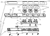
Fig. 1 is the split view that does not draw when opening the door module and lightning-protection module of the present utility model.
Fig. 2 is the enlarged diagram at the A place of Fig. 1.
Fig. 3 is schematic top plan view of the present utility model.
Among the figure: socket shell attachment screw 1, socket shell 2, base 21, fixed mount 22, switch installing hole 221, the first lightning-protection module installing hole 222, disjunctor socket shell installing hole 223, opening 2231, draw-in groove 2232, the second lightning-protection module installing hole 224, loam cake 23, the first lightning-protection module via hole 231, disjunctor socket shell via hole 232, the second lightning-protection module via hole 233, E utmost point inlet wire conducting strip 3, E utmost point sleeve 31, N utmost point inlet wire conducting strip 4, two or two utmost point N utmost point sleeves 41, two or three utmost point N utmost point sleeves 42, L utmost point inlet wire conducting strip 5, two or two utmost point L utmost point sleeves 51, two or three utmost point L utmost point sleeves 52, disjunctor socket shell 6, disjunctor socket panel 61, buckle 612, disjunctor socket isolating frame 62.
Embodiment
Below in conjunction with accompanying drawing and embodiment the utility model is further described.
Embodiment one, and referring to Fig. 1, a kind of multiposition socket comprises socket shell attachment screw 1, socket shell 2, a slice E utmost point inlet wire conducting strip 3, a slice N utmost point inlet wire conducting strip 4, a slice L utmost point inlet wire conducting strip 5 and 3 two disjunctor sockets.Because each two disjunctor socket has two socket positions, therefore have six socket positions in the present embodiment.
Seat shell attachment screw 1 has 9.
E utmost point inlet wire conducting strip 3 extends along the length direction of socket shell.E utmost point inlet wire conducting strip 3 is provided with two E utmost point sleeves 31.E utmost point sleeve 31 and E utmost point inlet wire conducting strip 3 are structure as a whole.
N utmost point inlet wire conducting strip 4 extends along the length direction of socket shell.N utmost point inlet wire conducting strip 4 is provided with two or two utmost point N utmost point sleeves 41 and two two or three utmost point N utmost point sleeves 42.Two or two utmost point N utmost point sleeve 41 comprise two along the socket shell Width N utmost point sleeve that namely fore-and-aft direction distributes among the figure, and two N utmost point sleeves in two or two utmost point N utmost point sleeves 41 are structure as a whole.Two N utmost point sleeves in two or two utmost point N utmost point sleeves 41 all are positioned at the place ahead of N utmost point inlet wire conducting strip 4 and are positioned at the rear of L utmost point inlet wire conducting strip 5.Two or three utmost point N utmost point sleeves 42 comprise two N utmost point sleeves that distribute along socket shell Width, and two N utmost point sleeves in two or three utmost point N utmost point sleeves 42 are structure as a whole.Two N utmost point sleeves in two or three utmost point N utmost point sleeves 42 all are positioned at the place ahead of N utmost point inlet wire conducting strip 4 and are positioned at the rear of L utmost point inlet wire conducting strip 5.
L utmost point inlet wire conducting strip 5 extends along the length direction of socket shell.L utmost point inlet wire conducting strip 5 is provided with two or two utmost point L utmost point sleeves 51 and two two or three utmost point L utmost point sleeves 52.Two or two utmost point L utmost point sleeves 51 comprise two L utmost point sleeves that distribute along socket shell Width, and two L utmost point sleeves in two or two utmost point L utmost point sleeves 51 are structure as a whole.Two L utmost point sleeves in two or two utmost point L utmost point sleeves 51 all are positioned at the place ahead of N utmost point inlet wire conducting strip 4 and are positioned at the rear of L utmost point inlet wire conducting strip 5.Two or two utmost point L utmost point sleeves 51 and two or two utmost point N utmost point sleeves 41 distribute along the length direction of socket shell.Two or three utmost point L utmost point sleeves 52 comprise two L utmost point sleeves that distribute along socket shell Width, and two L utmost point sleeves in two or three utmost point L utmost point sleeves 52 are structure as a whole.Two L utmost point sleeves in two or three utmost point L utmost point sleeves 52 are positioned at the place ahead of N utmost point inlet wire conducting strip 4 and are positioned at the rear of L utmost point inlet wire conducting strip 5.Two or three utmost point L utmost point sleeves 52 and two or three utmost point N utmost point sleeves 42 distribute along the length direction of socket shell.
Three two disjunctor sockets distribute along the length direction of socket shell.Leftmost that two disjunctors socket is that two or two utmost points, two disjunctor sockets, two other two disjunctors socket are two or three utmost points, two disjunctor sockets in three two disjunctor sockets.1 two or two utmost points, two disjunctor socket comprises 51,1 two or two utmost point N utmost point sleeve 41 of 1 two or two utmost point L utmost point sleeve and 1 disjunctor socket shell 6.1 two or three utmost points, two disjunctor socket comprises 52,1 42,1 E utmost point sleeve 31 of two or three utmost point N utmost point sleeves of 1 two or three utmost point L utmost point sleeve and 1 disjunctor socket shell 6.Disjunctor socket shell 6 comprises the disjunctor socket panel 61 of integrative-structure and the disjunctor socket isolating frame 62 of integrative-structure.When fitting together, the sleeve in the two disjunctor sockets separates by two disjunctor socket isolating frames 62.
Referring to Fig. 2, respectively be provided with two buckles 612 on the left and right side of disjunctor socket panel 61.Respectively be provided with two draw-in grooves 2232 and 2 openings 2231 on the left and right sides sidewall of disjunctor socket shell installing hole 223.Opening 2231 is with draw-in groove 2232 alignment.Opening 2231 begins to downward-extension from the upper surface of fixed mount 22.
The method that disjunctor socket shell is fitted together and is assembled on the fixed mount is: disjunctor socket isolating frame 62 is worn in the disjunctor socket shell installing hole 223, disjunctor socket panel 62 is covered on disjunctor socket isolating frame 62, and buckle 612 is stuck in the draw-in groove 2232 correspondingly.By removing to push buckle 612 with insertion openings 2231 such as straight screwdrivers disjunctor socket shell is taken off.
Referring to Fig. 3 and in conjunction with Fig. 1, the method that the utility model is fitted together is: E utmost point conducting strip 3, N utmost point conducting strip 4 and L utmost point conducting strip 5 are placed in the base 21, fixed mount 22 is placed on the base 21, disjunctor socket shell 6 is fixed on the fixed mount 22 according to aforesaid method correspondingly, switch 7, the first lightning-protection module 8 and the second module 9 are installed in the position of fixed mount 22 correspondences, loam cake 23 is covered on fixed mount 22, by socket shell connecting bolt 1 loam cake 23 and base 21 are locked together at last.Install rear utmost point conducting strip 3, N utmost point conducting strip 4 and L utmost point conducting strip 5 between fixed mount 22 and base 21.
Claims (10)
1. multiposition socket, comprise socket shell, N utmost point inlet wire conducting strip, L utmost point inlet wire conducting strip and at least six socket positions, each described socket position comprises the N utmost point sleeve and the L utmost point sleeve that links together with L utmost point inlet wire conducting strip that link together with N utmost point inlet wire conducting strip, it is characterized in that, described N utmost point inlet wire conducting strip only has a slice, and described L utmost point inlet wire conducting strip only has a slice.
2. multiposition socket according to claim 1, it is characterized in that, described socket shell is provided with two disjunctor sockets, two socket positions in the described two disjunctor sockets distribute along the Width of socket shell, and the L utmost point sleeve of same socket position and N utmost point sleeve distribute along the length direction of socket shell in the described two disjunctor sockets.
3. multiposition socket according to claim 2 is characterized in that, two L utmost point sleeves in the described two disjunctor sockets and two N utmost point sleeves are all between described L utmost point inlet wire conducting strip and N utmost point inlet wire conducting strip.
4. multiposition socket according to claim 3 is characterized in that, two L utmost point sleeves in the described two disjunctor sockets are structure as a whole, and two N utmost point sleeves in the described two disjunctor sockets are structure as a whole.
5. according to claim 2 or 3 or 4 described multiposition sockets, it is characterized in that, described two disjunctor sockets comprise disjunctor socket shell, described disjunctor socket shell comprises the disjunctor socket panel of integrative-structure and the disjunctor socket isolating frame of integrative-structure, and the sleeve in the described two disjunctor sockets separates by described disjunctor socket isolating frame.
6. multiposition socket according to claim 5, it is characterized in that, described socket shell comprises base, fixed mount and the loam cake that sets gradually along socket thickness of the shell direction, described N utmost point inlet wire conducting strip and L utmost point inlet wire conducting strip are between described fixed mount and base, described fixed mount is provided with disjunctor socket shell installing hole, described disjunctor socket shell wears and is fixed in the described disjunctor socket shell installing hole, is covered with the disjunctor socket via hole with described connection socket shell panel alignment on described.
7. multiposition socket according to claim 6 is characterized in that, described disjunctor socket shell installing hole is provided with draw-in groove, and the edge of described disjunctor socket panel is provided with buckle, and described buckle is contained in the described draw-in groove.
8. multiposition socket according to claim 7 is characterized in that, is provided with the opening that extends to described disjunctor socket panel upper surface between described disjunctor socket shell installing hole and the described disjunctor socket panel, and described opening aligns with described buckle.
9. multiposition socket according to claim 6 is characterized in that, described base is structure as a whole.
10. according to claim 1 and 2 or 3 or 4 described multiposition sockets, it is characterized in that, described socket shell comprises base, fixed mount and the loam cake that sets gradually along socket thickness of the shell direction, described N utmost point inlet wire conducting strip and L utmost point inlet wire conducting strip are between described fixed mount and base, and described base is structure as a whole.
Priority Applications (1)
| Application Number | Priority Date | Filing Date | Title |
|---|---|---|---|
| CN 201320247821 CN203250888U (en) | 2013-05-09 | 2013-05-09 | Multiposition socket |
Applications Claiming Priority (1)
| Application Number | Priority Date | Filing Date | Title |
|---|---|---|---|
| CN 201320247821 CN203250888U (en) | 2013-05-09 | 2013-05-09 | Multiposition socket |
Publications (1)
| Publication Number | Publication Date |
|---|---|
| CN203250888U true CN203250888U (en) | 2013-10-23 |
Family
ID=49377308
Family Applications (1)
| Application Number | Title | Priority Date | Filing Date |
|---|---|---|---|
| CN 201320247821 Expired - Lifetime CN203250888U (en) | 2013-05-09 | 2013-05-09 | Multiposition socket |
Country Status (1)
| Country | Link |
|---|---|
| CN (1) | CN203250888U (en) |
Cited By (2)
| Publication number | Priority date | Publication date | Assignee | Title |
|---|---|---|---|---|
| GB2521686A (en) * | 2013-12-31 | 2015-07-01 | Powertech Ind Co Ltd | One-piece conductor and method of manufacturing the same |
| CN106684622A (en) * | 2017-02-24 | 2017-05-17 | 宁波公牛电器有限公司 | Multi-position fixed socket-outlet with integrated conjoined inserting sleeves |
-
2013
- 2013-05-09 CN CN 201320247821 patent/CN203250888U/en not_active Expired - Lifetime
Cited By (4)
| Publication number | Priority date | Publication date | Assignee | Title |
|---|---|---|---|---|
| GB2521686A (en) * | 2013-12-31 | 2015-07-01 | Powertech Ind Co Ltd | One-piece conductor and method of manufacturing the same |
| GB2521686B (en) * | 2013-12-31 | 2015-12-09 | Powertech Ind Co Ltd | One-piece conductor and method of manufacturing the same |
| CN106684622A (en) * | 2017-02-24 | 2017-05-17 | 宁波公牛电器有限公司 | Multi-position fixed socket-outlet with integrated conjoined inserting sleeves |
| CN106684622B (en) * | 2017-02-24 | 2023-05-12 | 宁波公牛电器有限公司 | Multi-position fixed socket with integrated conjoined plug bush |
Similar Documents
| Publication | Publication Date | Title |
|---|---|---|
| CN201178147Y (en) | Electric connector | |
| CN204514978U (en) | Do not have a power failure and change table Intelligent meter box and the connector for electric energy meter plug seat | |
| CN203204041U (en) | Novel electric energy meter inserter | |
| CN203250888U (en) | Multiposition socket | |
| CN206041086U (en) | Multi -functional independent plug -in PDU | |
| US20150076907A1 (en) | Energy-saving power strip | |
| CN204517067U (en) | Do not have a power failure and change table plug seat | |
| CN203071262U (en) | LED power panel paired-plate connector | |
| CN104701692A (en) | Meter changing plug seat without power cut | |
| CN202737203U (en) | Rotary mounting type extension socket structure | |
| CN204118302U (en) | A kind of vehicle mounted guidance main frame and display screen are electrically connected structure-improved | |
| CN203707448U (en) | Double-connecting crystal plug | |
| CN210668795U (en) | Frame combined electric connector | |
| CN104576106A (en) | Connector for combination-type switch cassettes | |
| CN203690527U (en) | PCB board and wiring terminal strip connecting structure | |
| CN203119163U (en) | Socket protection door system and socket protection door | |
| CN205543404U (en) | Intelligent inserted row | |
| CN201918547U (en) | Power socket | |
| CN205543424U (en) | Live wire hardware of row of inserting | |
| CN101478102A (en) | Porous dual purpose low-voltage power supply socket | |
| CN200947493Y (en) | Improved structure of wafer socket | |
| CN205543502U (en) | A ground wire hardware for inserting arrange | |
| CN205724238U (en) | A kind of three plugs being easy to manufacture | |
| CN205194934U (en) | Female end of connector | |
| CN210744202U (en) | Locking PCB connector |
Legal Events
| Date | Code | Title | Description |
|---|---|---|---|
| C14 | Grant of patent or utility model | ||
| GR01 | Patent grant | ||
| CX01 | Expiry of patent term |
Granted publication date: 20131023 |
|
| CX01 | Expiry of patent term |