CN203242930U - Power distribution cabinet - Google Patents
Power distribution cabinet Download PDFInfo
- Publication number
- CN203242930U CN203242930U CN 201320268872 CN201320268872U CN203242930U CN 203242930 U CN203242930 U CN 203242930U CN 201320268872 CN201320268872 CN 201320268872 CN 201320268872 U CN201320268872 U CN 201320268872U CN 203242930 U CN203242930 U CN 203242930U
- Authority
- CN
- China
- Prior art keywords
- power distribution
- keyhole
- distribution cabinet
- slide rail
- shutter
- Prior art date
- Legal status (The legal status is an assumption and is not a legal conclusion. Google has not performed a legal analysis and makes no representation as to the accuracy of the status listed.)
- Expired - Fee Related
Links
Images

Landscapes
- Casings For Electric Apparatus (AREA)
Abstract
The utility model discloses a power distribution cabinet. The power distribution cabinet comprises a cabinet body; the cabinet body is provided with a keyhole; a shielding device is arranged at the periphery of the keyhole; the shielding device comprises a bottom plate as well as a shielding plate, double gears and a vertical sliding rail which are arranged on the bottom plate; an opening which is matched with the keyhole is formed on the bottom plate; the shielding plate is arranged above the opening; one side of the shielding plate is in slide connection through the vertical sliding rail, and the other side of the shielding plate is provided with cutter teeth; the cutter teeth are matched with the double gears; a transverse sliding rail is arranged below the double gears; the transverse sliding rail is provided with a rigid toothed bar used for driving the double gears to move; and a return spring is arranged between the rigid toothed bar and the vertical sliding rail. According to the power distribution cabinet of the utility model, the keyhole structure is provided with the shielding device, and therefore, the keyhole structure can be effectively protected, and man-made damage can be prevented.
Description
Technical field
The utility model relates to mechanical field, relates in particular to a kind of power distribution cabinet.
Background technology
Power distribution cabinet is mainly used in the classification configurations power supply, when circuit breaks down, be conducive to control fault coverage simultaneously fast and easy find out the fault point and in time discharged, the use convenient operation personnel burst of power distribution cabinet arranges line maintenance, and need not large-arealy have a power failure.Also be convenient in addition concentrate the various power distribution protection equipment of placing in the power distribution cabinet.
Door latch structure on the existing power distribution cabinet is simple, destroys easily, and especially the destruction of keyhole design so that the maintainer can't open, is brought great puzzlement to the maintainer when emergency.
The utility model content
The purpose of this utility model is the problem of mentioning in the above-mentioned background technology in order to solve, and a kind of power distribution cabinet is provided, and this power distribution cabinet is provided with a radical occlusion device in keyhole design, has effectively protected keyhole design, has prevented artificial destruction.
To achieve these goals, the technical solution of the utility model is as follows:
A kind of power distribution cabinet, comprise cabinet, be provided with keyhole on the described cabinet, described keyhole periphery is provided with a radical occlusion device, described radical occlusion device comprises base plate and is arranged on shutter on the base plate, Double-gear, vertical slide rail, also offer an opening that cooperates with keyhole on the described base plate, described shutter is arranged at described opening top, and a side is slidingly connected by vertical slide rail, described shutter opposite side is provided with cutter tooth, described cutter tooth cooperates with described Double-gear, described Double-gear below also is provided with horizontal slide rail, be provided with the rigid toothed of rotating for driving Double-gear on the described horizontal slide rail, be provided with a return spring between described rigid toothed and the described vertical slide rail.
Further, be provided with one on the described rigid toothed and be hook-shaped fixture.
Further, be provided with upper lever stopper above the described opening.
Further, except shutter, other structures all are coated in the bar section of stainless steel in the described radical occlusion device.
Shutter in the utility model; Double-gear; rigid toothed; return spring; vertical slide rail and laterally slide rail is integrated has formed one and can control the locking link gear that shutter moves up and down; remove shutter in this locking link gear; all the other structures all are coated in the bar section of stainless steel; when the maintainer need to open distribution box and carries out internal overhaul; utilize permanent strong magnets near radical occlusion device; and move towards the shutter left direction; the magnetic force of its permanent strong magnets sees through bar section of stainless steel; the pulling rigid toothed drives Double-gear and rotates, and makes shutter descending along vertical slide rail; expose keyhole; after the distribution box door lock is opened, remove permanent strong magnets, its rigid toothed will be under the effect of return spring; set back and put; thereby make shutter block keyhole, effectively protected keyhole design, prevented artificial destruction.
Further, be provided with one on the rigid toothed of the present utility model and be hook-shaped fixture and be used for inserting the Double-gear cutter tooth, thereby guarantee that other External Force Actings can not move up and down shutter.
Beneficial effect: unique, easy to operate, the flexibility and reliability of the utility model design.
Description of drawings
In order to be illustrated more clearly in the technical scheme of the utility model embodiment, the accompanying drawing of required use was done to introduce simply during the below will describe embodiment, apparently, accompanying drawing in the following describes only is embodiment more of the present utility model, for those of ordinary skills, under the prerequisite of not paying creative work, can also obtain according to these accompanying drawings other accompanying drawing.
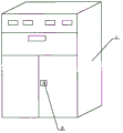
Fig. 1 is the structural representation in the present embodiment;
Fig. 2 is the radical occlusion device structural representation in the present embodiment;
Fig. 3 is the radical occlusion device structural representation in the present embodiment.
Embodiment
Below in conjunction with the accompanying drawing among the utility model embodiment, the technical scheme among the utility model embodiment is clearly and completely described, obviously, described embodiment only is the utility model part embodiment, rather than whole embodiment.Based on the embodiment in the utility model, those of ordinary skills are not making the every other embodiment that obtains under the creative work prerequisite, all belong to the scope of the utility model protection.
In conjunction with Fig. 1,2, a kind of power distribution cabinet in 3, comprise cabinet 1, be provided with keyhole 2 on the described cabinet 1, its keyhole 2 peripheries are provided with a radical occlusion device, radical occlusion device comprises base plate 3 and is arranged on shutter 4 on the base plate 3, Double-gear 5, vertical slide rail 6, also offer an opening 7 that cooperates with keyhole 2 on this base plate 3, its shutter 4 is arranged at described opening 7 tops, and a side is slidingly connected by vertical slide rail 6, its shutter 4 opposite sides are provided with cutter tooth, its cutter tooth cooperates with Double-gear 5, its Double-gear 5 belows also are provided with horizontal slide rail 7, be provided with the rigid toothed 10 of rotating for driving Double-gear 5 on its horizontal slide rail 7, be provided with a return spring 11 between its rigid toothed 10 and the vertical slide rail 6.
Shutter 4 in the present embodiment; Double-gear 5; rigid toothed 10; return spring 11; vertical slide rail 6 and laterally slide rail 9 is integrated has formed one and can control the locking link gear that shutter 4 moves up and down; remove shutter 4 in this locking link gear; all the other structures all are coated in the bar section of stainless steel; when the maintainer need to open distribution box and carries out internal overhaul; utilize permanent strong magnets near radical occlusion device; and move towards shutter 4 left directions; the magnetic force of its permanent strong magnets sees through bar section of stainless steel; pulling rigid toothed 10; driving Double-gear 5 rotates; and make shutter 4 descending along vertical slide rail 6; expose keyhole 2; after the distribution box door lock is opened, remove permanent strong magnets, its rigid toothed 10 will be under the effect of return spring 11; set back and put; thereby make shutter 4 block keyhole 2, effectively protected keyhole design, prevented artificial destruction.
In order to guarantee that other External Force Actings can not move up and down shutter 4, be provided with one on its rigid toothed 10 and be hook-shaped fixture 12, this hook-shaped fixture 12 is used for inserting Double-gear 5 cutters tooth, and shutter 4 drives Double-gear 5 because of External Force Acting and rotates.
In the present embodiment, opening 7 tops on its base plate 3 are provided with upper lever stopper 13.
The above only is preferred embodiment of the present utility model, not in order to limiting the utility model, all any modifications of doing, is equal to replacement etc. in protection range of the present utility model, all should be included within the protection range of the present utility model.
Claims (4)
1. power distribution cabinet, comprise cabinet, be provided with keyhole on the described cabinet, it is characterized in that, described keyhole periphery is provided with a radical occlusion device, described radical occlusion device comprises base plate and is arranged on shutter on the base plate, Double-gear, vertical slide rail, also offer an opening that cooperates with keyhole on the described base plate, described shutter is arranged at described opening top, and a side is slidingly connected by vertical slide rail, described shutter opposite side is provided with cutter tooth, described cutter tooth cooperates with described Double-gear, described Double-gear below also is provided with horizontal slide rail, is provided with the rigid toothed of rotating for driving Double-gear on the described horizontal slide rail, is provided with a return spring between described rigid toothed and the described vertical slide rail.
2. a kind of power distribution cabinet according to claim 1 is characterized in that, is provided with one on the described rigid toothed and is hook-shaped fixture.
3. a kind of power distribution cabinet according to claim 1 is characterized in that, described opening top is provided with upper lever stopper.
4. the described a kind of power distribution cabinet of any one is characterized in that according to claim 1-3, and except shutter, other structures all are coated in the bar section of stainless steel in the described radical occlusion device.
Priority Applications (1)
| Application Number | Priority Date | Filing Date | Title |
|---|---|---|---|
| CN 201320268872 CN203242930U (en) | 2013-05-17 | 2013-05-17 | Power distribution cabinet |
Applications Claiming Priority (1)
| Application Number | Priority Date | Filing Date | Title |
|---|---|---|---|
| CN 201320268872 CN203242930U (en) | 2013-05-17 | 2013-05-17 | Power distribution cabinet |
Publications (1)
| Publication Number | Publication Date |
|---|---|
| CN203242930U true CN203242930U (en) | 2013-10-16 |
Family
ID=49320189
Family Applications (1)
| Application Number | Title | Priority Date | Filing Date |
|---|---|---|---|
| CN 201320268872 Expired - Fee Related CN203242930U (en) | 2013-05-17 | 2013-05-17 | Power distribution cabinet |
Country Status (1)
| Country | Link |
|---|---|
| CN (1) | CN203242930U (en) |
Cited By (1)
| Publication number | Priority date | Publication date | Assignee | Title |
|---|---|---|---|---|
| CN108418132A (en) * | 2018-03-29 | 2018-08-17 | 福建省三星电气股份有限公司 | The anti-misoperation apparatus of high-tension switch cabinet |
-
2013
- 2013-05-17 CN CN 201320268872 patent/CN203242930U/en not_active Expired - Fee Related
Cited By (2)
| Publication number | Priority date | Publication date | Assignee | Title |
|---|---|---|---|---|
| CN108418132A (en) * | 2018-03-29 | 2018-08-17 | 福建省三星电气股份有限公司 | The anti-misoperation apparatus of high-tension switch cabinet |
| CN108418132B (en) * | 2018-03-29 | 2019-10-01 | 福建省三星电气股份有限公司 | The anti-misoperation apparatus of high-tension switch cabinet |
Similar Documents
| Publication | Publication Date | Title |
|---|---|---|
| CN205063705U (en) | Cabinet door of cold -stored storing show cupboard | |
| CN203660378U (en) | Closing locking operation device of switch cabinet | |
| CN202917882U (en) | Drawer cabinet interlock mechanism | |
| CN203242930U (en) | Power distribution cabinet | |
| CN203640482U (en) | Safety electric door | |
| CN203374101U (en) | High-voltage equipment box access cover fixing device | |
| CN202840334U (en) | Low-voltage switch cabinet drawer with interlocking mechanism | |
| CN205122421U (en) | Elevator block terminal | |
| CN201984976U (en) | Mine explosion-proof combined switch with locking function | |
| CN203135225U (en) | Isolation operation case | |
| CN105680337B (en) | The emergency unlocking mechanism at high-voltage complete switch equipment back door | |
| CN204905139U (en) | Solid insulated cabinets no. 5 prevents interlocking device | |
| CN203247952U (en) | ATM intelligent protection cabin lock hole shielding device | |
| CN205680360U (en) | Regulator cubicle label warning protective assembly | |
| CN203406548U (en) | Valve blocking mechanism | |
| CN202117454U (en) | Locking structure for front door and cable chamber door of switchgear | |
| CN202729542U (en) | Elevator door knife | |
| CN214899554U (en) | Balancer power distribution cabinet | |
| CN219418827U (en) | Equipment interlocking structure for safe operation of high-voltage cabinet | |
| CN205595264U (en) | Be suitable for isolator of narrow and small space divide -shut brake | |
| CN204225601U (en) | Coded lock blocking device | |
| CN205016419U (en) | Interlocking device | |
| CN203312645U (en) | Cabinet door interlocking device for ring main unit | |
| CN203644588U (en) | In-cabinet electric operating mechanism interlocking device with self-locking function | |
| CN203882831U (en) | Delicate interlocking plate of two fuse switches |
Legal Events
| Date | Code | Title | Description |
|---|---|---|---|
| C14 | Grant of patent or utility model | ||
| GR01 | Patent grant | ||
| CF01 | Termination of patent right due to non-payment of annual fee |
Granted publication date: 20131016 Termination date: 20150517 |
|
| EXPY | Termination of patent right or utility model |