CN203185408U - Limiting mechanism for light absorption piece cutting machine - Google Patents
Limiting mechanism for light absorption piece cutting machine Download PDFInfo
- Publication number
- CN203185408U CN203185408U CN 201320055117 CN201320055117U CN203185408U CN 203185408 U CN203185408 U CN 203185408U CN 201320055117 CN201320055117 CN 201320055117 CN 201320055117 U CN201320055117 U CN 201320055117U CN 203185408 U CN203185408 U CN 203185408U
- Authority
- CN
- China
- Prior art keywords
- guide rail
- stator
- lead screw
- hole
- limiting mechanism
- Prior art date
- Legal status (The legal status is an assumption and is not a legal conclusion. Google has not performed a legal analysis and makes no representation as to the accuracy of the status listed.)
- Expired - Fee Related
Links
Images
Abstract
The utility model discloses a limiting mechanism for a light absorption piece cutting machine. The limiting mechanism comprises a bottom plate and two lateral plates and is characterized in that a guide rail is arranged above the bottom plate between the two lateral plates, a fixing piece is arranged above the guide rail, a through hole is formed in the fixing piece, a sliding block capable of moving along the guide rail is arranged on the guide rail, one end of a screw rod penetrates through the through hole of the fixing piece to be clamped on the outer side of the through hole through a head of the screw rod, the other end of the screw rod is connected with the rear end of the sliding block, a limiting face is arranged at the front end of the sliding block, and a spring is sleeved on the screw rod. The limiting mechanism solves the problems that when light absorption piece raw materials are conveyed front and back on the cutting machine, the light absorption pieces raw materials can move left and right to affect follow-up piece cutting work, greatly reduce piece cutting accuracy, greatly improve product reject ratio and bring large loss to enterprises. The limiting mechanism is simple in structure convenient to use, capable of locating well, capable of guaranteeing follow-up cutting accuracy and capable of improving cutting quality.
Description
Technical field
The utility model relates to a kind of guillotine, particularly relates to a kind of extinction sheet guillotine position-limit mechanism.
Background technology
Automatically guillotine is that it is without any need for mould for the cutting apart and cut of the sheet material of all trades and professions; Control by systems soft ware, directly product is cut then, as long as set corresponding parameter at operating platform, guillotine is given in the corresponding instruction of computer transmission; Guillotine just cuts the automated procedures height fast according to the design picture proof of accepting; Simple to operate.It is the cutting apparatus that at present a lot of industries adopt.The extinction sheet is used in the field of emitting light and heat, utilize the extinction sheet to absorb the luminous energy generating of generating heat, and the extinction sheet generally all is baling, uses and the extinction sheet often needs to be cut into suitable sheet material, and this just need use guillotine and cut into slices, when but the extinction tablet raw material is carried before and after on guillotine, movement on the left and right displacement may take place, influence follow-up section work, the precision that causes cutting into slices descends greatly, product rejection rate improves greatly, has brought greater loss to enterprise.
The utility model content
When carrying before and after on guillotine in order to solve in the prior art extinction tablet raw material, movement on the left and right displacement may take place, influence follow-up section work, the precision that causes cutting into slices descends greatly, and product rejection rate improves greatly, bring the problem of greater loss to enterprise, it is a kind of simple in structure, easy to use that the utility model provides, and can better locate when carrying rolling extinction sheet, guarantee the follow-up precision that cuts, improve the extinction sheet guillotine position-limit mechanism that cuts quality.
In order to address the above problem, technical solution adopted in the utility model is:
A kind of extinction sheet guillotine position-limit mechanism, comprise base plate and two side plates, it is characterized in that: also comprise guide rail, stator, lead screw, slide block and spring, above base plate, be provided with guide rail between two side plates, above guide rail, be provided with stator, described stator is provided with a through hole, guide rail is provided with the slide block that can move along guide rail, one end of described lead screw passes the through hole of stator and the head by lead screw can be stuck in the through hole outside, the described lead screw other end is connected with the slide block rear end, and described slip front is provided with confined planes, is arranged with spring in lead screw.
Aforesaid a kind of extinction sheet guillotine position-limit mechanism is characterized in that: be provided with two limited posts in slip front.
Aforesaid a kind of extinction sheet guillotine position-limit mechanism, it is characterized in that: described stator equals 1/5 biside plate distance apart from the distance of one of them side plate.
Aforesaid a kind of extinction sheet guillotine position-limit mechanism is characterized in that: the height of described stator is lower than the height near stator one side side plate, and the height of described stator is higher than the height away from stator one side side plate.
The beneficial effects of the utility model are: an end of the lead screw of the utility model extinction sheet guillotine position-limit mechanism passes the through hole of stator and can be stuck in the through hole outside by nut, the described lead screw other end is connected with the slide block rear end, and described slip front is provided with limited post.When the extinction sheet of rolling passes position-limit mechanism like this, utilize the datum level of the limited post of slip front and extinction sheet runner one side on the guillotine to cooperate the extinction sheet is spacing, make it in moving process, move left and right can not take place, guarantee follow-uply to cut more accurately, the extinction sheet quality that cuts obtains powerful guarantee.Simultaneously be arranged with spring in lead screw, like this when extinction sheet width is big, slide block can be along guide rail side shifting backward, and it is mobile backward that lead screw is also passed through hole, and the spring extruding that is subjected to stator at this moment produces deformation power, and to make that the slide block limited post carries out the extinction sheet spacing preferably.
Description of drawings
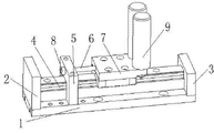
Fig. 1 is the structural representation of the utility model extinction sheet guillotine position-limit mechanism.
The specific embodiment
The utility model will be further described below in conjunction with accompanying drawing.
As shown in Figure 1, a kind of extinction sheet guillotine position-limit mechanism, comprise base plate 1, side plate 2, side plate 3, guide rail 4, stator 5, lead screw 6, slide block 7 and spring, above base plate 1, be provided with guide rail 4 between side plate 2 and the side plate 3, above guide rail 4, be provided with stator 5, described stator 5 is provided with a through hole, guide rail 4 is provided with the slide block 7 that can move along guide rail 4, one end of described lead screw 6 passes the through hole of stator and can be stuck in the through hole outside by 8 of lead screw, described lead screw 6 other ends are connected with slide block 7 rear ends, described slide block 7 front ends are provided with limited post, limited post can axially freely rotate along self, is provided with two limited posts 9 at slide block 7 front ends.Be arranged with spring in lead screw 6.
During design, in order to reach best result of use, stator 5 equals 1/5 biside plate distance apart from the distance of side plate 2.The height of stator 5 is lower than the height near stator 5 one side side plates 2, and the height of described stator 5 is higher than the height away from stator 5 one side side plates 3.
One end of the lead screw 6 of the utility model extinction sheet guillotine position-limit mechanism passes the through hole of stator and can be stuck in the through hole outside by 88 of nut lead screw, described lead screw 6 other ends are connected with slide block 7 rear ends, and described slide block 7 front ends are provided with limited post.When the extinction sheet of rolling passes position-limit mechanism like this, utilize the datum level side plate 3 of extinction sheet runner one side on the limited post of slide block 7 front ends and the guillotine to cooperate the extinction sheet is spacing, make it in moving process, move left and right can not take place, guarantee follow-uply to cut more accurately, the extinction sheet quality that cuts obtains powerful guarantee.Simultaneously be arranged with spring in lead screw 6, like this when extinction sheet width is big, slide block 7 can be along guide rail 4 side shifting backward, and it is mobile backward that lead screw 6 is also passed through hole, and the spring extruding that is subjected to stator 5 at this moment produces deformation power, and to make that slide block 7 limited posts carry out the extinction sheet spacing preferably.
More than show and described basic principle of the present utility model, principal character and advantage.The technical staff of the industry should understand; the utility model is not restricted to the described embodiments; that describes in above-described embodiment and the specification just illustrates principle of the present utility model; under the prerequisite that does not break away from the utility model spirit and scope; the utility model also has various changes and modifications, and these changes and improvements all fall in claimed the utility model scope.The claimed scope of the utility model is defined by appending claims and equivalent thereof.
Claims (4)
1. extinction sheet guillotine position-limit mechanism, comprise base plate and two side plates, it is characterized in that: also comprise guide rail, stator, lead screw, slide block and spring, above base plate, be provided with guide rail between two side plates, above guide rail, be provided with stator, described stator is provided with a through hole, guide rail is provided with the slide block that can move along guide rail, one end of described lead screw passes the through hole of stator and the head by lead screw can be stuck in the through hole outside, the described lead screw other end is connected with the slide block rear end, and described slip front is provided with confined planes, is arranged with spring in lead screw.
2. a kind of extinction sheet guillotine position-limit mechanism according to claim 1 is characterized in that: be provided with two limited posts in slip front.
3. a kind of extinction sheet guillotine position-limit mechanism according to claim 2, it is characterized in that: described stator equals 1/5 biside plate distance apart from the distance of one of them side plate.
4. a kind of extinction sheet guillotine position-limit mechanism according to claim 3 is characterized in that: the height of described stator is lower than the height near stator one side side plate, and the height of described stator is higher than the height away from stator one side side plate.
Priority Applications (1)
| Application Number | Priority Date | Filing Date | Title |
|---|---|---|---|
| CN 201320055117 CN203185408U (en) | 2013-01-31 | 2013-01-31 | Limiting mechanism for light absorption piece cutting machine |
Applications Claiming Priority (1)
| Application Number | Priority Date | Filing Date | Title |
|---|---|---|---|
| CN 201320055117 CN203185408U (en) | 2013-01-31 | 2013-01-31 | Limiting mechanism for light absorption piece cutting machine |
Publications (1)
| Publication Number | Publication Date |
|---|---|
| CN203185408U true CN203185408U (en) | 2013-09-11 |
Family
ID=49102296
Family Applications (1)
| Application Number | Title | Priority Date | Filing Date |
|---|---|---|---|
| CN 201320055117 Expired - Fee Related CN203185408U (en) | 2013-01-31 | 2013-01-31 | Limiting mechanism for light absorption piece cutting machine |
Country Status (1)
| Country | Link |
|---|---|
| CN (1) | CN203185408U (en) |
Cited By (1)
| Publication number | Priority date | Publication date | Assignee | Title |
|---|---|---|---|---|
| CN105798960A (en) * | 2016-05-10 | 2016-07-27 | 无为县宏喜体育用品有限公司 | Auxiliary cutting device for feather shank of single feather |
-
2013
- 2013-01-31 CN CN 201320055117 patent/CN203185408U/en not_active Expired - Fee Related
Cited By (2)
| Publication number | Priority date | Publication date | Assignee | Title |
|---|---|---|---|---|
| CN105798960A (en) * | 2016-05-10 | 2016-07-27 | 无为县宏喜体育用品有限公司 | Auxiliary cutting device for feather shank of single feather |
| CN105798960B (en) * | 2016-05-10 | 2017-11-28 | 无为县宏喜体育用品有限公司 | A kind of monolithic feather plumage handle aids in Scissoring device |
Similar Documents
| Publication | Publication Date | Title |
|---|---|---|
| CN104441065B (en) | It is applicable to the cutting cutter of rule sheet material | |
| CN202702411U (en) | Gantry line stone cutting machine | |
| CN204012143U (en) | A kind of S7 terminal guillotine | |
| CN204685783U (en) | A kind of type of cutting seat being applicable to different product | |
| CN203185389U (en) | Light absorption piece cutting machine | |
| CN203140654U (en) | Electronic element pin cutting machine | |
| CN204135470U (en) | A kind of metallic plate cutter device | |
| CN203185408U (en) | Limiting mechanism for light absorption piece cutting machine | |
| CN203077355U (en) | Small-type high-accuracy cutting machine | |
| CN204309214U (en) | Automatic cutter mechanism and water gap cutter | |
| CN103112032A (en) | Limiting mechanism of light-absorbing-piece cutting machine | |
| CN204800773U (en) | But wooden cutting machine of multi -angle cutting | |
| CN103586940A (en) | Equal dividing and cutting mechanism for wooden-door excess materials | |
| CN203726520U (en) | Paper slicing machine | |
| CN203565960U (en) | Plate opening machining device | |
| CN203343537U (en) | Cutting machine tool | |
| CN104552448A (en) | Punching device for sealing strips for automobile foreside windscreen | |
| CN204220734U (en) | Narrow case macropore punching mechanism | |
| CN204505486U (en) | A kind of doorframe one-shaper | |
| CN204430418U (en) | Window frame machine for rolling parts continuous cutting-off frock | |
| CN203304670U (en) | Fixed and steady automatic stainless steel plate dadoing device | |
| CN203449393U (en) | Bench saw with aiming device | |
| CN203563759U (en) | Laser-cutting device of knitted vamp | |
| CN203380920U (en) | Plastic film slitting machine | |
| CN203140983U (en) | Multi-head laser cutting machine |
Legal Events
| Date | Code | Title | Description |
|---|---|---|---|
| C14 | Grant of patent or utility model | ||
| GR01 | Patent grant | ||
| C17 | Cessation of patent right | ||
| CF01 | Termination of patent right due to non-payment of annual fee |
Granted publication date: 20130911 Termination date: 20140131 |