CN203184087U - Cutter - Google Patents
Cutter Download PDFInfo
- Publication number
- CN203184087U CN203184087U CN 201320073327 CN201320073327U CN203184087U CN 203184087 U CN203184087 U CN 203184087U CN 201320073327 CN201320073327 CN 201320073327 CN 201320073327 U CN201320073327 U CN 201320073327U CN 203184087 U CN203184087 U CN 203184087U
- Authority
- CN
- China
- Prior art keywords
- cutting
- cutter
- cutting machine
- blade
- cutter sweep
- Prior art date
- Legal status (The legal status is an assumption and is not a legal conclusion. Google has not performed a legal analysis and makes no representation as to the accuracy of the status listed.)
- Expired - Lifetime
Links
Images

Landscapes
- Crushing And Pulverization Processes (AREA)
Abstract
The utility model relates to a mechanical device, and in particular relates to a cutter suitable for crushing organic or inorganic solids in a heterogeneous liquid. The cutter comprises a base, a motor, a hydraulic regulating device, a cutting device, a feed port and a discharge port, wherein an original liquid material enters from the feed port and is discharged from the discharge port after being cut by the cutting device; a heavy matter separating chamber and a foreign matter discharging outlet are formed on the cutter; heavy matters such as metal, stone and the like in the original liquid material are discharged from the foreign matter discharging outlet in the heavy matter separating chamber; a sluice chamber and a filtering screen are also arranged on the cutter. The cutter is used for performing the liquid cutting, and the technical problem that the conventional cutter blade is abraded inconsistently and rapidly is solved. The cutter is uniform in cutting, realizes noise reduction and shock absorption and can be used for effectively preventing a pump and a downstream pipeline from being blocked and enhancing the liquid fluidity as well as cutting the solid materials into small granules to facilitate subsequent treatment.
Description
Technical field
The utility model relates to a kind of mechanical device, and especially a kind of rotary knife cutter field that relates to is applicable to the cutter sweep of pulverizing the organic or inorganic solid in the homogenous liquid not.
Background technology
At present cutting machine in use, blade abrasion is inhomogeneous, blade can not be adjusted in the process of operation with the gap between the cutting screen, material and shape that cutting is shielded can not guarantee good cutting effect and the uniformity of blade abrasion.Cause the wearing and tearing of blade later stage very fast like this, and need early to change blade, cause operating efficiency to reduce, increase maintenance cost.
Therefore, need to solve the reasonable use that realizes blade by the adjustment of cutting screen and blade, postpone blade service life, the assurance cutting efficiency is stablized the cut quality of cutting machine, reduction personnel and maintenance cost.
The utility model content
In order to improve the inconsistent and technical problem faster of wearing and tearing of conventional cutting machine blade wearing and tearing; the utility model discloses a kind of new liquid cutting equipment; protection pump and downstream line do not stop up, increase liquid flow properties, solid material is cut into granule, is convenient to the industry of subsequent treatment and processing.
Cutting machine of the present utility model, comprise base, motor, hydraulic adjustment device, cutter sweep, charging aperture, discharging opening, the described cutter sweep of described driven by motor, stoste liquid material enters from charging aperture, discharge from described discharging opening by cutter sweep cutting back, it is characterized in that described cutting machine is provided with weight separation chamber and foreign matter outlet, the inorganic matter that the metal in the raw material, stone etc. are heavier is discharged by the foreign matter outlet in the separation chamber.The weight separation chamber that is positioned at base cabinet has the effect that weight separates, and accelerates separation process, reduces unnecessary cutting process, prolongs the life-span of cutter sweep and blade, guarantees that weight does not damage blade and cutting screen.
Further, this cutting machine is provided with upper chamber, and described upper chamber is positioned at the top of cutter sweep, and described upper chamber is provided with filter screen.
Further, this cutter sweep is provided with flying knife, and described flying knife is arranged on the circular cutter holder, and described circular cutter holder is arranged on and transmits on the bearing, and described drive bearing passes through driven by motor, and is controlled by the peripheral hardware motor control box, can realize rotating.
Further, the blade of this device flying knife and circular cutter holder adopt the latch fixed form.
Further, this revolution blade adopts the hydraulic pump hydraulic control mode.
Further, this revolution blade is provided with the cutting screen device that adapts with blade shapes, and closely contacts in working order with cutting screen, guarantees good cutting effect.
Further, this cutting screen adopts involute shape; Cutting screen special geometric form guarantees the uniformity of cutting and the uniformity of blade abrasion.
Simultaneously cutting machine externally under the control of control cabinet, has power-on protection, blade rotating, functions such as blade abrasion demonstration.
Adopt above structure, compared with prior art, the utlity model has following advantage: the cutter alternative, cutter sweep and blade obviously prolong service life, the wear condition of cutting blade has higher uniformity, it is evenly good to cut, and plays the effect of noise reduction, damping simultaneously, adopts the latch fixed form also to be beneficial to follow-up cutting machine maintenance and blade exchange.
Description of drawings
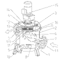
Fig. 1 is structural representation of the present utility model.
Fig. 2 has the overall structure schematic diagram of Flywheel disc for the utility model.
Reference numeral:
1. 18. Flywheel discs are shielded in 17. cuttings of base 1-1. charging aperture 2. weight separation chambers 3. cutter sweeps, 4. upper chambers, 5. discharging openings 6. coarse fodders 7. fibrous materials 8. stones 9. bonding jumpers 10. foreign matter outlets 11. flying knife 11-1 circular cutter holders 12. filter screens 13. cutting back materials 14. drive bearings 15. motors 16. hydraulic adjustment devices
The specific embodiment
Cutting machine as figure, comprise base 1, motor 15, cutter sweep 3, charging aperture 1-1, discharging opening 5, stoste liquid material enters from charging aperture 1-1, discharge from described discharging opening 5 by cutter sweep 3 cutting backs, this cutting machine also is provided with weight separation chamber 2 and foreign matter outlet 10, and the inorganic matter that the metal in the raw material, stone etc. are heavier etc. 2 are discharged by foreign matter outlet 10 in the weight separation chamber.The weight separation chamber 2 that is positioned at base cabinet has the effect that weight separates, and accelerates separation process, reduces unnecessary cutting process, prolongs the life-span of cutter sweep and blade, guarantees that weight does not damage blade.
This cutting machine also is provided with upper chamber 4, and described upper chamber is positioned at the top of cutter sweep 3, and described upper chamber is provided with filter screen 12.
Further, this cutter sweep is provided with flying knife 11, and described flying knife is arranged on the circular cutter holder 11-1, described circular cutter holder 11-1 is arranged on and transmits on the bearing 14, described drive bearing 14 drives by motor 15, and is controlled by the peripheral hardware motor control box, can realize rotating; This revolution blade adopts the hydraulic pump hydraulic control mode.
Embodiment 2: on the basis of enforcement 1, also increased Flywheel disc 18, in order to increase the stability of bearing transferring power, and increased cutting force.
The utility model relates to the liquid cutting; improved the inconsistent and technical problem faster of wearing and tearing of conventional cutting machine blade wearing and tearing; cutting evenly, noise reduction, damping; can effectively protect pump and downstream line not to stop up, increase liquid flow properties, solid material is cut into granule, is convenient to subsequent treatment.
Claims (7)
1. cutting machine, comprise base, motor, hydraulic adjustment device, cutter sweep, charging aperture, discharging opening, the described cutter sweep of described driven by motor, stoste liquid material enters from charging aperture, discharge from described discharging opening by cutter sweep cutting back, it is characterized in that described cutting machine is provided with weight separation chamber and foreign matter outlet.
2. cutting machine according to claim 1 is characterized in that described cutter sweep is provided with upper chamber, and described upper chamber is positioned at the top of cutter sweep, and described upper chamber is provided with filter screen.
3. cutting machine according to claim 1, it is characterized in that described cutter sweep is provided with flying knife, described flying knife is arranged on the circular cutter holder, and described circular cutter holder is arranged on and transmits on the bearing, described drive bearing passes through driven by motor, and is controlled by the peripheral hardware motor control box.
4. cutting machine according to claim 3 is characterized in that the blade of described flying knife and described circular cutter holder adopt the latch fixed form.
5. cutting machine according to claim 3 is characterized in that described revolution blade adopts the hydraulic pump hydraulic control mode.
6. cutting machine according to claim 3 is characterized in that described revolution blade is provided with the cutting screen device that adapts with blade shapes, and closely contacts in working order with cutting screen.
7. cutting machine according to claim 7 is characterized in that described cutting screen adopts involute shape.
Priority Applications (1)
| Application Number | Priority Date | Filing Date | Title |
|---|---|---|---|
| CN 201320073327 CN203184087U (en) | 2013-02-16 | 2013-02-16 | Cutter |
Applications Claiming Priority (1)
| Application Number | Priority Date | Filing Date | Title |
|---|---|---|---|
| CN 201320073327 CN203184087U (en) | 2013-02-16 | 2013-02-16 | Cutter |
Publications (1)
| Publication Number | Publication Date |
|---|---|
| CN203184087U true CN203184087U (en) | 2013-09-11 |
Family
ID=49100987
Family Applications (1)
| Application Number | Title | Priority Date | Filing Date |
|---|---|---|---|
| CN 201320073327 Expired - Lifetime CN203184087U (en) | 2013-02-16 | 2013-02-16 | Cutter |
Country Status (1)
| Country | Link |
|---|---|
| CN (1) | CN203184087U (en) |
Cited By (2)
| Publication number | Priority date | Publication date | Assignee | Title |
|---|---|---|---|---|
| CN106064110A (en) * | 2015-04-22 | 2016-11-02 | 史红钻 | Slurrying conveyer is pulverized in fluid slagging-off |
| CN107249749A (en) * | 2014-12-22 | 2017-10-13 | 福格申机械有限公司 | Solid material discharges module |
-
2013
- 2013-02-16 CN CN 201320073327 patent/CN203184087U/en not_active Expired - Lifetime
Cited By (4)
| Publication number | Priority date | Publication date | Assignee | Title |
|---|---|---|---|---|
| CN107249749A (en) * | 2014-12-22 | 2017-10-13 | 福格申机械有限公司 | Solid material discharges module |
| US10639641B2 (en) | 2014-12-22 | 2020-05-05 | Hugo Vogelsang Maschinenbau Gmbh | Solids discharge module |
| CN107249749B (en) * | 2014-12-22 | 2020-09-04 | 福格申机械有限公司 | Solid material discharge module |
| CN106064110A (en) * | 2015-04-22 | 2016-11-02 | 史红钻 | Slurrying conveyer is pulverized in fluid slagging-off |
Similar Documents
| Publication | Publication Date | Title |
|---|---|---|
| CN203990745U (en) | A kind of veterinary drug reducing mechanism | |
| CN205361537U (en) | Flour mill | |
| CN210753034U (en) | Bean food grinding device | |
| CN104014397B (en) | Millstone crusher | |
| CN204544295U (en) | A kind of micronizer | |
| CN204656613U (en) | Collection crushing and screening is recovered as the system of processing of one | |
| CN105750044A (en) | Spiral pulverizer | |
| CN203184087U (en) | Cutter | |
| CN202028446U (en) | Crusher for hard materials | |
| CN204320421U (en) | A kind of domestic waste disintegrating machine | |
| CN213792063U (en) | Flour mill | |
| CN204974022U (en) | Lime stone milling equipment | |
| CN207913917U (en) | A kind of pulverizer with inclined hole sieve | |
| CN203108627U (en) | Veterinary drug grinder | |
| CN202860606U (en) | Efficient colloid mill | |
| CN102240585A (en) | Special-purposed pulverizer for coal mine fire extinguishing high hygrophanous resin, and application method thereof | |
| CN210207151U (en) | Fine crushing device for three-section tailing discarding process | |
| CN209663397U (en) | A kind of antiwear crushing and pelletizing machine | |
| CN208944212U (en) | A kind of dust-proof mining sand shaker | |
| CN203764349U (en) | Vertical type crushing machine | |
| CN205095846U (en) | Automatic change high -efficient rubbing crusher | |
| CN203459116U (en) | Scraper knife on raymond mill for producing silicon carbide fine powder and raymond mill constructed by scraper knife | |
| CN203678463U (en) | Pulverizer | |
| CN105214799A (en) | A kind of equipment pulverized for coating | |
| CN206484692U (en) | A kind of Wood filings machine of raw material for fir essential oil separation and Extraction |
Legal Events
| Date | Code | Title | Description |
|---|---|---|---|
| C14 | Grant of patent or utility model | ||
| GR01 | Patent grant | ||
| CX01 | Expiry of patent term | ||
| CX01 | Expiry of patent term |
Granted publication date: 20130911 |