CN203173701U - Novel universal bridge crane - Google Patents
Novel universal bridge crane Download PDFInfo
- Publication number
- CN203173701U CN203173701U CN 201320115243 CN201320115243U CN203173701U CN 203173701 U CN203173701 U CN 203173701U CN 201320115243 CN201320115243 CN 201320115243 CN 201320115243 U CN201320115243 U CN 201320115243U CN 203173701 U CN203173701 U CN 203173701U
- Authority
- CN
- China
- Prior art keywords
- road wheel
- track
- auxiliary
- crane
- rails
- Prior art date
- Legal status (The legal status is an assumption and is not a legal conclusion. Google has not performed a legal analysis and makes no representation as to the accuracy of the status listed.)
- Expired - Fee Related
Links
Images

Abstract
The utility model relates to a novel universal bridge crane and aims to provide an energy-saving and safe universal bridge crane. The universal bridge crane comprises girders, support legs, travelling trolley and an electronic hoist and is characterized in that rails are arranged on upper surfaces of the two girders which are on the left and the right; main travelling wheels matched with the rails are arranged at the bottoms of two ends of the travelling trolley and are connected with a power mechanism; auxiliary rails are arranged on the travelling trolley, and the extending direction of the auxiliary rails is vertical to the rails; the auxiliary rails are matched with auxiliary travelling wheels on an auxiliary trolley; auxiliary travelling wheel wheels are connected with a power mechanism; the electronic hoist is distributed on the auxiliary trolley; a trolley and a hook of the crane can accurately reach an appointed working place, so that energy consumption for moving the whole crane can be saved, and safety accidents caused when people move the hook can be avoided. The bridge crane is energy-saving and economical, is safe in use, and has a wide application prospect.
Description
Technical field
The utility model relates to hoisting crane, is specifically related to a kind of general-purpose overhead crane.
Background technology
Hoisting crane belongs to a kind of of elevator machinery, and its principle of work is: load-engaging device is mentioned article from getting thing ground, is moved horizontally to the appointed place then and falls article, then carries out counter motion, makes the load-engaging device reposition, in order to circulate next time.
General-purpose overhead crane mainly by: girder traveling gear, carriage walking mechanism, lifting mechanism and electrical equipment are formed.The crane span structure two ends are bearing on the aerial conveyor in factory building or the sky, open depot by the girder traveling gear, vertically move along track; Walking dolly laterally moves at crane span structure girder upper edge trolley track, and lifting mechanism is generally the structure that electric block drives hook-type, grab bucket type or magnetic chuck type.
But in existing general-purpose overhead crane, walking dolly can only will can only rely on the girder traveling gear perpendicular to the motion of girder direction along the length cross motion of girder.But girder and walking dolly overall dimensions, weight are big, walking is difficult to accurate control, be difficult to accurately put in place when causing hoisting weight, adopt for lifting mechanism in the hoisting crane of hook-type, grab bucket type, dolly even need personnel to assist the suspension hook on the electric block or grab bucket are moved into place repeatedly need be movably walking.So not only increase equipment energy consumption, also caused safety misadventure easily.
Summary of the invention
Main purpose of the present utility model provides a kind of energy-conservation, safe general-purpose overhead crane.
Concrete technical scheme of the present utility model is: general-purpose overhead crane, comprise girder, walking dolly and electric block, it is characterized in that: described girder comprises left and right two, both arrange track by upper surface, the bottom at described walking dolly two ends arranges the main road wheel that cooperates with track, and main road wheel connects actuating unit; Secondary track is set on the walking dolly, and bearing of trend and the track of secondary track are perpendicular, and secondary track cooperates with secondary road wheel on the secondary dolly, and secondary road wheel connects actuating unit, and described electric block is arranged on the secondary dolly; Each evenly arranges 4 groups to described main road wheel at the walking dolly two ends.
Further, described every group of master's road wheel has two wheels; Described secondary road wheel arranges 8 at every secondary track.
Further, the actuating unit that described and secondary road wheel is connected comprises drive motor, and described drive motor is stepping motor.Perhaps, described secondary road wheel periphery is set to arc toothed, and the waveform tooth that matches with secondary road wheel is set on the described secondary track.So all being beneficial to electric block stably walks and parks the location.
Technique effect intentionally of the present utility model: be equivalent to be provided with major-minor two cover traveling geaies on the general-purpose overhead crane of the present utility model, can especially can suitably move along the direction perpendicular to girder with electric block along moving perpendicular to girder and the direction that is parallel to girder.During work, the mobile supporting leg of elder generation, make girder integral body move into place, then by the main road wheel of control, the integral body dolly that is movably walking by the position of secondary road wheel fine setting electric block, can accurately arrive the appointed working place point then, can save the energy consumption of mobile whole hoisting crane, can avoid personnel to move suspension hook again and cause safety misadventure.The utility model energy saving economy uses safety, has broad application prospects.
Description of drawings
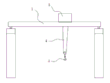
Fig. 1 is the structural representation of general-purpose overhead crane;
Fig. 2 is the structural representation of walking dolly;
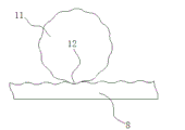
Fig. 3 is secondary track and the scheme drawing that cooperates of secondary road wheel.
The specific embodiment
Novel universal crane in bridge type preferred embodiment as shown in Figure 1, 2 comprises that girder 1, girder 1 two ends are formed on the aerial conveyor by walking dolly 3.The moving walking dolly 3 of road wheel rotating band is along the track longitudinal movement under actuating unit drives.Described girder 1 comprises left and right two, both upper surfaces arrange track 6, the bottom at described walking dolly 3 two ends arranges the main road wheel that cooperates with track 6, main road wheel connects actuating unit 7, actuating unit comprises motor, retarder, control system etc., is used for driving main road wheel and moves along track 6.Secondary track 8 is set on the walking dolly 3, bearing of trend and the track 6 of secondary track 8 are perpendicular, secondary track 8 cooperates with secondary road wheel 11 on the secondary dolly 9, secondary road wheel 11 connects actuating unit 10, the version of this actuating unit can be identical or different with actuating unit 7, even the two cover outputs that both share same set of motivation mechanism also are fine.Electric block 4 is arranged on the secondary dolly 9, and electric block 4 drives the suspension hooks 5 up-and-down movements weight of slinging.Each evenly arranges 4 groups to main road wheel at walking dolly 3 two ends.
The utility model has realized that not only the electric block position can move along girder 1 with perpendicular to girder 1, and saves the energy consumption that whole hoisting crane moves by the position of finely tuning secondary dolly 9, uses also safer.The preferred number of main road wheel arranges and ensures that the application force of main walking dolly on girder 1 evenly disperses.Make equipment performance reliable, ensure that also the movement of secondary dolly is with steady.Preferably, described every group of master's road wheel has two wheels; Described secondary road wheel 11 arranges 8 at every secondary track 8.
Further preferred, the actuating unit that described and secondary road wheel 11 is connected comprises drive motor, and described drive motor is stepping motor.So secondary dolly 9 ground displacements can be controlled more accurately.Perhaps as shown in Figure 3, secondary road wheel 11 peripheries of stating are set to arc toothed, and the waveform tooth 12 that matches with secondary road wheel 11 is set on the described secondary track 8.Adopt common electric machine also can make movement and the accurate positioning, stable of secondary dolly 9 like this.
Crane hook 5 of the present utility model can accurately arrive the appointed working place point, can save the energy consumption of mobile whole hoisting crane, can avoid personnel to move suspension hook again and cause safety misadventure.The utility model energy saving economy uses safety, has broad application prospects.
Claims (4)
1. novel universal crane in bridge type, comprise girder (1), walking dolly (3) and electric block (4), it is characterized in that: described girder (1) comprises left and right two, both upper surfaces arrange track (6), the bottom at described walking dolly (3) two ends arranges the main road wheel that cooperates with track (6), and main road wheel connects actuating unit; Secondary track (8) is set on the walking dolly (3), bearing of trend and the track (6) of secondary track (8) are perpendicular, secondary track (8) cooperates with secondary road wheel (11) on the secondary dolly (9), secondary road wheel (11) connects actuating unit, and described electric block (4) is arranged on the secondary dolly (9); Each evenly arranges 4 groups to described main road wheel at walking dolly (3) two ends.
2. novel universal crane in bridge type according to claim 1, it is characterized in that: described every group of master's road wheel has two wheels; Described secondary road wheel (11) arranges 8 at every secondary track (8).
3. novel universal crane in bridge type according to claim 1 and 2, it is characterized in that: the actuating unit that described and secondary road wheel (11) is connected comprises drive motor, described drive motor is stepping motor.
4. novel universal crane in bridge type according to claim 1 and 2, it is characterized in that: described secondary road wheel (11) periphery is set to arc toothed, and described secondary track (8) is gone up the waveform tooth (12) that matches with secondary road wheel (11) is set.
Priority Applications (1)
| Application Number | Priority Date | Filing Date | Title |
|---|---|---|---|
| CN 201320115243 CN203173701U (en) | 2013-03-14 | 2013-03-14 | Novel universal bridge crane |
Applications Claiming Priority (1)
| Application Number | Priority Date | Filing Date | Title |
|---|---|---|---|
| CN 201320115243 CN203173701U (en) | 2013-03-14 | 2013-03-14 | Novel universal bridge crane |
Publications (1)
| Publication Number | Publication Date |
|---|---|
| CN203173701U true CN203173701U (en) | 2013-09-04 |
Family
ID=49070435
Family Applications (1)
| Application Number | Title | Priority Date | Filing Date |
|---|---|---|---|
| CN 201320115243 Expired - Fee Related CN203173701U (en) | 2013-03-14 | 2013-03-14 | Novel universal bridge crane |
Country Status (1)
| Country | Link |
|---|---|
| CN (1) | CN203173701U (en) |
Cited By (3)
| Publication number | Priority date | Publication date | Assignee | Title |
|---|---|---|---|---|
| CN103466447A (en) * | 2013-09-12 | 2013-12-25 | 天津起重设备有限公司 | Crane travelling trolley for micro-control assembly |
| CN104555850A (en) * | 2015-01-07 | 2015-04-29 | 中冶华天工程技术有限公司 | Ladle and steel ladle tipping device |
| CN106327945A (en) * | 2016-09-28 | 2017-01-11 | 上海海事大学 | Crane simulator somatic simulation method and device |
-
2013
- 2013-03-14 CN CN 201320115243 patent/CN203173701U/en not_active Expired - Fee Related
Cited By (4)
| Publication number | Priority date | Publication date | Assignee | Title |
|---|---|---|---|---|
| CN103466447A (en) * | 2013-09-12 | 2013-12-25 | 天津起重设备有限公司 | Crane travelling trolley for micro-control assembly |
| CN104555850A (en) * | 2015-01-07 | 2015-04-29 | 中冶华天工程技术有限公司 | Ladle and steel ladle tipping device |
| CN106327945A (en) * | 2016-09-28 | 2017-01-11 | 上海海事大学 | Crane simulator somatic simulation method and device |
| CN106327945B (en) * | 2016-09-28 | 2019-04-30 | 上海海事大学 | A kind of counterweight simulator proprioceptive simulation method and apparatus |
Similar Documents
| Publication | Publication Date | Title |
|---|---|---|
| CN203173701U (en) | Novel universal bridge crane | |
| CN204510844U (en) | A kind of large-span steel girder high-altitude mounting slip device | |
| CN203048424U (en) | Mobile type chain block | |
| CN203845710U (en) | Automobile production line welding station switching device | |
| CN203173706U (en) | Novel gantry crane | |
| CN203247031U (en) | Hoisting device for curtain board transporting | |
| CN202465067U (en) | Crane cart traveling mechanism with travel switch | |
| CN207891733U (en) | The mobile operation platform of steel truss arched bridge coating project | |
| CN202429920U (en) | Multi-trolley and double-girder gantry crane | |
| CN204778464U (en) | Shield constructs gantry crane for subway | |
| CN103572976B (en) | A kind of multi-functional slippage flat car and annular building mounting slip system | |
| CN205171288U (en) | Magnetism floats section of track and moves gantry crane | |
| CN204137896U (en) | The new type carting machine of baking-free building block adobe for building | |
| CN205114887U (en) | Hand propelled removes portal frame | |
| CN204185773U (en) | A kind of Bridge Erector rail moves rail device | |
| CN202245805U (en) | Traveling gantry crane | |
| CN204625001U (en) | A kind of simple and easy multidirectional hanging apparatus | |
| CN202913360U (en) | Bridge floor rotary hoisting device | |
| CN203578756U (en) | Slide water gap sand filling device | |
| CN202465101U (en) | Bridge-type crane with temporary trolley | |
| CN203903800U (en) | Gantry crane with electric hoist and capable of reducing total weight | |
| CN202465111U (en) | Large shipbuilding gantry crane with anemobiagraph | |
| CN202465114U (en) | Easily maintainable large-sized ship building gantry crane | |
| CN202465097U (en) | Bridge crane with slidable electronic control cabinet | |
| CN202429884U (en) | Large-tonnage ultralong gantry crane |
Legal Events
| Date | Code | Title | Description |
|---|---|---|---|
| C14 | Grant of patent or utility model | ||
| GR01 | Patent grant | ||
| CF01 | Termination of patent right due to non-payment of annual fee | ||
| CF01 | Termination of patent right due to non-payment of annual fee |
Granted publication date: 20130904 Termination date: 20170314 |