CN203171181U - Welding clamp for car seat framework assembly - Google Patents
Welding clamp for car seat framework assembly Download PDFInfo
- Publication number
- CN203171181U CN203171181U CN 201320164190 CN201320164190U CN203171181U CN 203171181 U CN203171181 U CN 203171181U CN 201320164190 CN201320164190 CN 201320164190 CN 201320164190 U CN201320164190 U CN 201320164190U CN 203171181 U CN203171181 U CN 203171181U
- Authority
- CN
- China
- Prior art keywords
- supporting
- support
- support compression
- supporting mechanism
- hold
- Prior art date
- Legal status (The legal status is an assumption and is not a legal conclusion. Google has not performed a legal analysis and makes no representation as to the accuracy of the status listed.)
- Expired - Fee Related
Links
Images
Abstract
A welding clamp for a car seat framework assembly relates to the field of car producing equipment and comprises a bottom plate, a first support pressing mechanism, a first pin penetrating mechanism, a first pressing mechanism, a first support mechanism, a second pressing mechanism, a second support mechanism, a third pressing mechanism, a second support pressing mechanism, a third support mechanism, a fourth pressing mechanism, a third support pressing mechanism, a second pin penetrating mechanism, a third pin penetrating mechanism, a fourth pin penetrating mechanism, a fourth support mechanism, a fifth support mechanism, a fifth pin penetrating mechanism, a sixth pin penetrating mechanism, a fourth support pressing mechanism, a fifth support pressing mechanism, a sixth support mechanism, a seventh support mechanism and a fifth pressing mechanism. The welding clamp for the car seat framework assembly can overcome the shortages of the prior art, is convenient to operate, easy to assemble, reliable in clamping and positioning, capable of greatly improving the production efficiency and welding quality, simple in structure and easy for promotion and usage.
Description
Technical field:
The utility model relates to a kind of automobile production equipment, is specifically related to a kind of automobile chair frame assembly welding clamp.
Background technology:
High-end autobody sheet frame-type chair framework, complex structure, number of welds is many, status requirement is accurate, and artificial welding is difficult to reach, and quality and efficient are difficult to reach production requirement, welding robot is welding field, particularly a kind of automatic welding equipment of weld car field extensive use needs special clamp clamps workpiece during the welding robot welding, and existing anchor clamps can't be realized standardization, design cycle is long, production efficiency and welding quality are low, and complex structure, the cost of manufacture height.
The utility model content:
The purpose of this utility model provides a kind of automobile chair frame assembly welding clamp, and it can overcome the deficiencies in the prior art, and is easy to operate, be easy to assembling, clamp and locate reliably, can enhance productivity greatly and welding quality, simple in structure, be easy to promote and use.
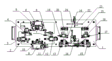
In order to solve the existing problem of background technology, the utility model is by the following technical solutions: it comprises base plate 1, the first support compression mechanism 2, first wears pin mechanism 3, first hold-down mechanism 4, first supporting mechanism 5, second hold-down mechanism 6, second supporting mechanism 7, the 3rd hold-down mechanism 8, the second support compression mechanism 9, the 3rd supporting mechanism 10, the 4th hold-down mechanism 11, the 3rd support compression mechanism 12, second wears pin mechanism 13, the 3rd wears pin mechanism 14, the 4th wears pin mechanism 15, the 4th supporting mechanism 16, the 5th supporting mechanism 17, the 5th wears pin mechanism 18, the 6th wears pin mechanism 19, the 4th support compression mechanism 20, the 5th support compression mechanism 21, the 6th supporting mechanism 22, the 7th supporting mechanism 23 and the 5th hold-down mechanism 24, an end is provided with the first support compression mechanism 2 on the base plate 1, the first support compression mechanism, 2 upper ends are provided with first and wear pin mechanism 3, first wears pin mechanism 3 is provided with first hold-down mechanism 4, first upper end, right side of wearing pin mechanism 3 is provided with first supporting mechanism 5, first supporting mechanism 5 is provided with second hold-down mechanism 6, the lower end, right side of first supporting mechanism 5 is provided with second supporting mechanism 7, second supporting mechanism 7 is provided with second hold-down mechanism 8, the lower end, left side of second supporting mechanism 7 is provided with the second support compression mechanism 9, the upper end of the second support compression mechanism 9 is provided with the 3rd supporting mechanism 10, the right-hand member of the second support compression mechanism 9 is provided with the 4th hold-down mechanism 11, the lower end of second supporting mechanism 7 is provided with the 3rd support compression mechanism 12, the lower end, right side of the 3rd support compression mechanism 12 is provided with second and wears pin mechanism 13, second right side of wearing pin mechanism 13 is provided with the 3rd and wears pin mechanism 14, the 3rd right side of wearing pin mechanism 14 is provided with the 4th and wears pin mechanism 15, second upper end of wearing pin mechanism 13 is provided with the 4th supporting mechanism 16, the 4th supporting mechanism 16 is provided with the 5th and wears pin mechanism 18, the 4th upper end of wearing pin mechanism 15 is provided with the 5th supporting mechanism 17, the 5th supporting mechanism 17 is provided with the 6th and wears pin mechanism 19, the upper end of the 4th supporting mechanism 16 is provided with the 4th support compression mechanism 20, the upper end of the 5th supporting mechanism 17 is provided with the 5th support compression mechanism 21, the upper end, middle part of the 4th support compression mechanism 20 and the 5th support compression mechanism 21 is provided with the 6th supporting mechanism 22, the upper end that the top of the 6th supporting mechanism 22 is provided with the 7th supporting mechanism 23, the six supporting mechanisms 22 is provided with the 5th hold-down mechanism 24.
Described base plate 1 each side be provided with a plate 25.
The utility model can overcome the deficiencies in the prior art, and is easy to operate, is easy to assembling, clamps and locatees reliably, can enhance productivity greatly and welding quality, simple in structure, is easy to promote and use.
Description of drawings:
Fig. 1 is structural representation of the present utility model;
Fig. 2 is the left view of Fig. 1.
The specific embodiment:
Referring to Fig. 1, Fig. 2, this specific embodiment is by the following technical solutions: it comprises base plate 1, the first support compression mechanism 2, first wears pin mechanism 3, first hold-down mechanism 4, first supporting mechanism 5, second hold-down mechanism 6, second supporting mechanism 7, the 3rd hold-down mechanism 8, the second support compression mechanism 9, the 3rd supporting mechanism 10, the 4th hold-down mechanism 11, the 3rd support compression mechanism 12, second wears pin mechanism 13, the 3rd wears pin mechanism 14, the 4th wears pin mechanism 15, the 4th supporting mechanism 16, the 5th supporting mechanism 17, the 5th wears pin mechanism 18, the 6th wears pin mechanism 19, the 4th support compression mechanism 20, the 5th support compression mechanism 21, the 6th supporting mechanism 22, the 7th supporting mechanism 23 and the 5th hold-down mechanism 24, an end is provided with the first support compression mechanism 2 on the base plate 1, the first support compression mechanism, 2 upper ends are provided with first and wear pin mechanism 3, first wears pin mechanism 3 is provided with first hold-down mechanism 4, first upper end, right side of wearing pin mechanism 3 is provided with first supporting mechanism 5, first supporting mechanism 5 is provided with second hold-down mechanism 6, the lower end, right side of first supporting mechanism 5 is provided with second supporting mechanism 7, second supporting mechanism 7 is provided with second hold-down mechanism 8, the lower end, left side of second supporting mechanism 7 is provided with the second support compression mechanism 9, the upper end of the second support compression mechanism 9 is provided with the 3rd supporting mechanism 10, the right-hand member of the second support compression mechanism 9 is provided with the 4th hold-down mechanism 11, the lower end of second supporting mechanism 7 is provided with the 3rd support compression mechanism 12, the lower end, right side of the 3rd support compression mechanism 12 is provided with second and wears pin mechanism 13, second right side of wearing pin mechanism 13 is provided with the 3rd and wears pin mechanism 14, the 3rd right side of wearing pin mechanism 14 is provided with the 4th and wears pin mechanism 15, second upper end of wearing pin mechanism 13 is provided with the 4th supporting mechanism 16, the 4th supporting mechanism 16 is provided with the 5th and wears pin mechanism 18, the 4th upper end of wearing pin mechanism 15 is provided with the 5th supporting mechanism 17, the 5th supporting mechanism 17 is provided with the 6th and wears pin mechanism 19, the upper end of the 4th supporting mechanism 16 is provided with the 4th support compression mechanism 20, the upper end of the 5th supporting mechanism 17 is provided with the 5th support compression mechanism 21, the upper end, middle part of the 4th support compression mechanism 20 and the 5th support compression mechanism 21 is provided with the 6th supporting mechanism 22, the upper end that the top of the 6th supporting mechanism 22 is provided with the 7th supporting mechanism 23, the six supporting mechanisms 22 is provided with the 5th hold-down mechanism 24.
Described base plate 1 each side be provided with a plate 25.
This specific embodiment can overcome the deficiencies in the prior art, and is easy to operate, is easy to assembling, clamps and locatees reliably, can enhance productivity greatly and welding quality, simple in structure, is easy to promote and use.
Claims (2)
1. automobile chair frame assembly welding clamp, it is characterized in that it comprises base plate (1), the first support compression mechanism (2), first wears pin mechanism (3), first hold-down mechanism (4), first supporting mechanism (5), second hold-down mechanism (6), second supporting mechanism (7), the 3rd hold-down mechanism (8), the second support compression mechanism (9), the 3rd supporting mechanism (10), the 4th hold-down mechanism (11), the 3rd support compression mechanism (12), second wears pin mechanism (13), the 3rd wears pin mechanism (14), the 4th wears pin mechanism (15), the 4th supporting mechanism (16), the 5th supporting mechanism (17), the 5th wears pin mechanism (18), the 6th wears pin mechanism (19), the 4th support compression mechanism (20), the 5th support compression mechanism (21), the 6th supporting mechanism (22), the 7th supporting mechanism (23) and the 5th hold-down mechanism (24), the last end of base plate (1) is provided with the first support compression mechanism (2), the first support compression mechanism (2) upper end is provided with first and wears pin mechanism (3), first wears pin mechanism (3) is provided with first hold-down mechanism (4), first upper end, right side of wearing pin mechanism (3) is provided with first supporting mechanism (5), first supporting mechanism (5) is provided with second hold-down mechanism (6), the lower end, right side of first supporting mechanism (5) is provided with second supporting mechanism (7), second supporting mechanism (7) is provided with second hold-down mechanism (8), the lower end, left side of second supporting mechanism (7) is provided with the second support compression mechanism (9), the upper end of the second support compression mechanism (9) is provided with the 3rd supporting mechanism (10), the right-hand member of the second support compression mechanism (9) is provided with the 4th hold-down mechanism (11), the lower end of second supporting mechanism (7) is provided with the 3rd support compression mechanism (12), the lower end, right side of the 3rd support compression mechanism (12) is provided with second and wears pin mechanism (13), second right side of wearing pin mechanism (13) is provided with the 3rd and wears pin mechanism (14), the 3rd right side of wearing pin mechanism (14) is provided with the 4th and wears pin mechanism (15), second upper end of wearing pin mechanism (13) is provided with the 4th supporting mechanism (16), the 4th supporting mechanism (16) is provided with the 5th and wears pin mechanism (18), the 4th upper end of wearing pin mechanism (15) is provided with the 5th supporting mechanism (17), the 5th supporting mechanism (17) is provided with the 6th and wears pin mechanism (19), the upper end of the 4th supporting mechanism (16) is provided with the 4th support compression mechanism (20), the upper end of the 5th supporting mechanism (17) is provided with the 5th support compression mechanism (21), the upper end, middle part of the 4th support compression mechanism (20) and the 5th support compression mechanism (21) is provided with the 6th supporting mechanism (22), the top of the 6th supporting mechanism (22) is provided with the 7th supporting mechanism (23), and the upper end of the 6th supporting mechanism (22) is provided with the 5th hold-down mechanism (24).
2. a kind of automobile chair frame assembly welding clamp according to claim 1, what it is characterized in that described base plate (1) each side is provided with a plate (25).
Priority Applications (1)
| Application Number | Priority Date | Filing Date | Title |
|---|---|---|---|
| CN 201320164190 CN203171181U (en) | 2013-04-04 | 2013-04-04 | Welding clamp for car seat framework assembly |
Applications Claiming Priority (1)
| Application Number | Priority Date | Filing Date | Title |
|---|---|---|---|
| CN 201320164190 CN203171181U (en) | 2013-04-04 | 2013-04-04 | Welding clamp for car seat framework assembly |
Publications (1)
| Publication Number | Publication Date |
|---|---|
| CN203171181U true CN203171181U (en) | 2013-09-04 |
Family
ID=49067934
Family Applications (1)
| Application Number | Title | Priority Date | Filing Date |
|---|---|---|---|
| CN 201320164190 Expired - Fee Related CN203171181U (en) | 2013-04-04 | 2013-04-04 | Welding clamp for car seat framework assembly |
Country Status (1)
| Country | Link |
|---|---|
| CN (1) | CN203171181U (en) |
Cited By (14)
| Publication number | Priority date | Publication date | Assignee | Title |
|---|---|---|---|---|
| CN104785934A (en) * | 2015-04-03 | 2015-07-22 | 蓝姆汽车焊接设备(上海)有限公司 | Automobile seat cushion automatic welding production line and production method thereof |
| CN105328390A (en) * | 2015-12-11 | 2016-02-17 | 重庆创力工贸有限公司 | Method for welding and fixing seat frame assembly of front-row seat |
| CN105328391A (en) * | 2015-12-11 | 2016-02-17 | 重庆创力工贸有限公司 | Automobile seat headrest framework welding clamp |
| CN105345301A (en) * | 2015-12-18 | 2016-02-24 | 重庆创力工贸有限公司 | Method for welding backrest framework of automotive seat |
| CN105345360A (en) * | 2015-12-11 | 2016-02-24 | 重庆创力工贸有限公司 | Welding clamp for sitting frame assembly of front seat |
| CN105345302A (en) * | 2015-12-18 | 2016-02-24 | 重庆创力工贸有限公司 | Welding technology of backrest framework of automotive seat |
| CN105345367A (en) * | 2015-12-11 | 2016-02-24 | 重庆创力工贸有限公司 | Welding device for seat frame assembly of front-row seat |
| CN105397372A (en) * | 2015-12-18 | 2016-03-16 | 重庆创力工贸有限公司 | Method for welding backrest framework of automobile seat |
| CN105414860A (en) * | 2016-01-12 | 2016-03-23 | 武汉理工大学 | Welding fixture for automobile seat part |
| CN105458589A (en) * | 2016-01-06 | 2016-04-06 | 柳州市超群汽车配件有限责任公司 | Dumping gear welding clamp for automobile additional seats and method for assembling dumping gear by using same |
| CN105643170A (en) * | 2014-11-11 | 2016-06-08 | 上海申龙客车有限公司 | Welding device for front-section frame of double-windshield vehicle frame |
| CN105817814A (en) * | 2016-05-09 | 2016-08-03 | 重庆格机械制造有限公司 | Automobile steel wire seat welding device |
| CN106112371A (en) * | 2016-08-27 | 2016-11-16 | 宁波明望汽车饰件有限公司 | For producing the welding tooling of automobile chair frame |
| CN107825054A (en) * | 2017-12-13 | 2018-03-23 | 重庆朝旺机械制造有限公司 | Four points of seat support rack weld jigs |
-
2013
- 2013-04-04 CN CN 201320164190 patent/CN203171181U/en not_active Expired - Fee Related
Cited By (20)
| Publication number | Priority date | Publication date | Assignee | Title |
|---|---|---|---|---|
| CN105643170A (en) * | 2014-11-11 | 2016-06-08 | 上海申龙客车有限公司 | Welding device for front-section frame of double-windshield vehicle frame |
| CN105643170B (en) * | 2014-11-11 | 2018-01-26 | 上海申龙客车有限公司 | A kind of welder of double windscreen front section of vehicle frame skeletons |
| CN104785934A (en) * | 2015-04-03 | 2015-07-22 | 蓝姆汽车焊接设备(上海)有限公司 | Automobile seat cushion automatic welding production line and production method thereof |
| CN105328390A (en) * | 2015-12-11 | 2016-02-17 | 重庆创力工贸有限公司 | Method for welding and fixing seat frame assembly of front-row seat |
| CN105328391A (en) * | 2015-12-11 | 2016-02-17 | 重庆创力工贸有限公司 | Automobile seat headrest framework welding clamp |
| CN105345360A (en) * | 2015-12-11 | 2016-02-24 | 重庆创力工贸有限公司 | Welding clamp for sitting frame assembly of front seat |
| CN105345367A (en) * | 2015-12-11 | 2016-02-24 | 重庆创力工贸有限公司 | Welding device for seat frame assembly of front-row seat |
| CN105345302A (en) * | 2015-12-18 | 2016-02-24 | 重庆创力工贸有限公司 | Welding technology of backrest framework of automotive seat |
| CN105397372A (en) * | 2015-12-18 | 2016-03-16 | 重庆创力工贸有限公司 | Method for welding backrest framework of automobile seat |
| CN105345301A (en) * | 2015-12-18 | 2016-02-24 | 重庆创力工贸有限公司 | Method for welding backrest framework of automotive seat |
| CN105458589A (en) * | 2016-01-06 | 2016-04-06 | 柳州市超群汽车配件有限责任公司 | Dumping gear welding clamp for automobile additional seats and method for assembling dumping gear by using same |
| CN105458589B (en) * | 2016-01-06 | 2017-05-17 | 柳州市超群汽车配件有限责任公司 | Dumping gear welding clamp for automobile additional seats and method for assembling dumping gear by using same |
| CN105414860A (en) * | 2016-01-12 | 2016-03-23 | 武汉理工大学 | Welding fixture for automobile seat part |
| CN105414860B (en) * | 2016-01-12 | 2017-03-22 | 武汉理工大学 | Welding fixture for automobile seat part |
| CN105817814A (en) * | 2016-05-09 | 2016-08-03 | 重庆格机械制造有限公司 | Automobile steel wire seat welding device |
| CN105817814B (en) * | 2016-05-09 | 2017-11-21 | 重庆格一机械制造有限公司 | Wire seat for automobile welder |
| CN106112371A (en) * | 2016-08-27 | 2016-11-16 | 宁波明望汽车饰件有限公司 | For producing the welding tooling of automobile chair frame |
| CN106112371B (en) * | 2016-08-27 | 2017-10-24 | 宁波明望汽车饰件有限公司 | Welding tooling for producing automobile chair frame |
| CN107825054A (en) * | 2017-12-13 | 2018-03-23 | 重庆朝旺机械制造有限公司 | Four points of seat support rack weld jigs |
| CN107825054B (en) * | 2017-12-13 | 2019-04-19 | 重庆朝旺机械制造有限公司 | Four points of seat support rack welding fixtures |
Similar Documents
| Publication | Publication Date | Title |
|---|---|---|
| CN203171181U (en) | Welding clamp for car seat framework assembly | |
| CN204108570U (en) | Chair framework weld jig | |
| CN203062146U (en) | Automobile welding fixture | |
| CN202185701U (en) | Automatic welding fixture for front axle welded parts of automobiles | |
| CN202763355U (en) | Steering column support block and middle frame welding fixture of framework of automobile instrument panel | |
| CN201900404U (en) | Fixture for welding cold-rolled sheets | |
| CN202291940U (en) | Automatic welding fixture for automobile front axle weldment | |
| CN203109514U (en) | Welding clamp used for automobile roof drip | |
| CN203062133U (en) | Upper base welding jig of elevator traction machine frame | |
| CN202317451U (en) | Compaction device for laser welding of nickel sheet to copper sheet | |
| CN202367317U (en) | Fixture for welding wires and pins (PIN) | |
| CN101985196B (en) | Device for welding walking frame main body of excavator | |
| CN202356550U (en) | Lamp head wire pressing mold | |
| CN201900380U (en) | Positioning device for welding of projection welding nut | |
| CN201783790U (en) | Hardware welding clamp for mobile phone battery | |
| CN202224861U (en) | Device for welding safety tongs of elevator | |
| CN202344156U (en) | Bracket mistake proofing device on rear right shock absorber of multi-purpose vehicle (MPV) | |
| CN202991766U (en) | Clip structure | |
| CN201913418U (en) | Clamp for fixing RS232 interface | |
| CN203459868U (en) | Welding fixture | |
| CN203649716U (en) | Welding fixture for sheet metal | |
| CN202199970U (en) | Flat bulb steel welding support | |
| CN203146491U (en) | Plastic part for fastener | |
| CN205733580U (en) | Charging pile robot arm welding tooling | |
| CN204470876U (en) | Motorcycle battery pole group welding special tooling |
Legal Events
| Date | Code | Title | Description |
|---|---|---|---|
| C14 | Grant of patent or utility model | ||
| GR01 | Patent grant | ||
| C17 | Cessation of patent right | ||
| CF01 | Termination of patent right due to non-payment of annual fee |
Granted publication date: 20130904 Termination date: 20140404 |