CN203169539U - Paraplegic walking device - Google Patents
Paraplegic walking device Download PDFInfo
- Publication number
- CN203169539U CN203169539U CN 201320129672 CN201320129672U CN203169539U CN 203169539 U CN203169539 U CN 203169539U CN 201320129672 CN201320129672 CN 201320129672 CN 201320129672 U CN201320129672 U CN 201320129672U CN 203169539 U CN203169539 U CN 203169539U
- Authority
- CN
- China
- Prior art keywords
- knee joint
- hip joint
- walking device
- lockset
- cable
- Prior art date
- Legal status (The legal status is an assumption and is not a legal conclusion. Google has not performed a legal analysis and makes no representation as to the accuracy of the status listed.)
- Expired - Fee Related
Links
Images
Abstract
The utility model relates to a paraplegic walking device comprising two ankle protecting sleeves, two sets of knee joint assemblies, two sets of hip joint assemblies, a waist soft cushion, a buttock soft cushion, a supporting steel tube and two steel bars, wherein the two ankle protecting sleeves are sequentially connected with the corresponding knee joint assemblies and the corresponding hip joint assemblies from bottom to top, the hip joint assemblies are connected through the supporting steel tube, and the waist soft cushion and the buttock soft cushion are elastically connected between the hip joint assemblies. The paraplegic walking device is convenient to use, safe and reliable, a portable external mechanical system is used as a skeletal system, a patient can wear clothes normally, the device is convenient to wear, the patient with basic training can use the device which is a novel standing walking brace, and therefore the paraplegic walking device is more suitable for practical use and has industrial utilization value.
Description
Technical field
This utility model relates to the medical health apparatus field, particularly a kind of paraplegia walking device.
Background technology
This utility model relates to the stand external machinery of human body of walking of a kind of reciprocating type power-assisted, is applicable to the patient who causes paraplegia because of the forfeiture of spinal cord injury and all lower-limb muscular strengths, is used for the brace of standing and walking.It can be considered a kind of external skeletal system, in order to body support, the remaining kinetic energy of health is converted to forward power, is particularly suitable for the patient of all lower-limb muscular strength severes forfeitures.
At present, some panplegias or high paraplegia patient in the society, long-term roller chair life brings a lot of inconvenience and misery to them, and they imagine the same the standing and walking of normal person very much; This utility model designs a kind of easy to use, safe and reliable, light external mechanical system is as skeletal system, they are partly lived can take care of oneself, can go touches society finishes some social activity, work in power and housework also can make patient's physiological system normal operation simultaneously; Owing to can stand and walk and just can make each system's operate as normal of patient self, for example reduce urinary system infection, increase digestive system activity etc.The patient also needs normally dressing, dresses conveniently, knows a little and just train and can use the walking brace of standing.
Released the brace of some types in the society, most generally speaking brace structure is simple or complicated, but is purpose standing all, does not realize walking; What perhaps have can walk reluctantly, but the huge heaviness of its structure makes the patient more handicapped.
This shows that the above-mentioned existing walking brace of standing obviously still has inconvenience and defective, and demands urgently further being improved in structure and use.In order to solve the problem that the walking brace of standing exists, relevant manufacturer there's no one who doesn't or isn't seeks solution painstakingly, but do not see always that for a long time suitable design finished by development, and common product does not have appropriate structure to address the above problem, and this obviously is the problem that the anxious desire of relevant dealer solves.
Because the defective that the above-mentioned existing walking brace of standing exists, the design people is based on being engaged in practical experience and the Professional knowledge that this type of product design manufacturing is enriched for many years, and the utilization of cooperation scientific principle, actively studied innovation, in the hope of founding a kind of paraplegia walking device of new structure, can improve the general existing walking brace of standing, make it have more practicality.Through constantly research, design, and after studying sample and improvement repeatedly, create this utility model that has practical value finally.
In view of this, this utility model provides a kind of power-assist type paraplegia device that walks upright.
Summary of the invention
At defective of the prior art, the purpose of this utility model provides a kind of paraplegia walking device, overcome the difficulty of prior art, easy to use, safe and reliable, light external mechanical system makes normally dressing of patient, dresses conveniently, trains a little the novel walking brace of standing that just can use as skeletal system, thereby be suitable for practicality more, and have the value on the industry.
According to an aspect of the present utility model, a kind of paraplegia walking device is provided, comprise two ankle foot protection covers, two groups of knee joint assemblies, two groups of hip joint assemblies, a waist cushion, a buttocks cushion, a supporting steel pipe and two steel bars; Two described ankle foot protection covers connect corresponding described knee joint assembly and hip joint assembly from top to bottom successively; laterally connect by described supporting steel pipe between the described hip joint assembly, described waist cushion and buttocks cushion elasticity are connected between the described hip joint assembly.
Preferably, two described steel bars are separately fixed at the outside that two described ankle foot protections overlap;
The described knee joint assembly of each described ankle foot protection cover top comprises knee joint revolving part, knee joint lockset, steelframe, gas column spring and knee joint cable; The lower end of the described steelframe described knee joint revolving part that is rotationally connected, the be rotationally connected upper end of described steel bar, the lower end of described knee joint revolving part, described gas column spring is connected between described steelframe and the described knee joint revolving part, and described knee joint revolving part arranges one and is subjected to described knee joint cable interlock and the described knee joint lockset that opens and closes;
Described hip joint assembly comprises hip joint connector, hip joint drive cable, side stand and hip joint lockset; Fixedly connected by screw with described steelframe in the inboard of described hip joint connector, the outside of described hip joint connector is connected with side stand, described hip joint lockset is set on the described side stand, and fixedly connected two side stands of described hip joint drive cable difference.
Preferably, when described knee joint cable was relaxed, described knee joint cable drove the locked described knee joint revolving part of described knee joint lockset, stops the rotation between described steelframe, knee joint revolving part and the steel bar.
Preferably, described knee joint cable one end connects described knee joint lockset, and the other end connects described hip joint connector.
Preferably, described knee joint assembly also comprises a spring protection cover, and described spring protection cover coats described steelframe and gas column spring.
Preferably, described ankle foot protection cover upper edge horizontal plane direction arranges at least one bandage.
Preferably, described waist cushion upper edge horizontal plane direction arranges at least one bandage.
Preferably, described buttocks cushion upper edge horizontal plane direction arranges at least one bandage.
Preferably, described knee joint lockset and/or hip joint lockset are the locksets of hand switch.
Compared with prior art, owing to used above technology, a kind of paraplegia walking device of the present utility model is easy to use, safe and reliable, light external mechanical system is as skeletal system, make normally dressing of patient, dress conveniently, train the novel walking brace of standing that just can use a little, thereby be suitable for practicality more, and have the value on the industry.
Description of drawings
By reading the detailed description of non-limiting example being done with reference to the following drawings, it is more obvious that other features, objects and advantages of the present utility model will become:
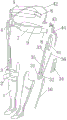
Fig. 1 illustrates according to a specific embodiment of the present utility model, the explosive view of a kind of paraplegia walking device of the present utility model.
Reference numeral
1 ankle foot protection cover
2 bandages
3 knee joint assemblies
31 knee joint revolving parts
32 knee joint locksets
33 steelframes
34 spring protection covers
35 gas column springs
36 knee joint cables
4 hip joint assemblies
41 hip joint connectors
42 hip joint drive cable
43 side stands
44 hip joint locksets
5 waist cushions
6 bandages
7 buttocks cushions
8 bandages
9 supporting steel pipes
10 steel bars
The specific embodiment
It will be appreciated by those skilled in the art that those skilled in the art can realize described variation example in conjunction with prior art and above-described embodiment, do not repeat them here.Such variation example does not influence flesh and blood of the present utility model, does not repeat them here.
Fig. 1 illustrates according to a specific embodiment of the present utility model, the schematic appearance of a kind of paraplegia walking device of the present utility model.As shown in Figure 1, a kind of paraplegia walking device of the present utility model comprises 1, two group of knee joint assembly 3 of two ankle foot protection covers, two groups of hip joint assemblies 4, a waist cushion 5, a buttocks cushion 7, a supporting steel pipe 9 and two steel bars 10.Two described ankle foot protection covers 1 connect corresponding described knee joint assembly 3 and hip joint assembly 4 from top to bottom successively; laterally connect by described supporting steel pipe 9 between two groups of described hip joint assemblies 4, described waist cushion 5 and buttocks cushion 7 elasticity are connected between two groups of described hip joint assemblies 4.Described waist cushion 5 and buttocks cushion 7 can be protected waist and the buttocks that supports the patient respectively, absorb the vibration of walking to patient's influence, are convenient to the patient and are kept upright or walk posture.
Two described steel bars 10 are separately fixed at the outside of two described ankle foot protection covers 1.
Knee joint assembly 3 is positioned at corresponding ankle foot protection and overlaps 1 top, and each described knee joint assembly 3 comprises knee joint revolving part 31, knee joint lockset 32, steelframe 33, gas column spring 35 and knee joint cable 36.The lower end of the described steelframe 33 described knee joint revolving part 31 that is rotationally connected, the be rotationally connected upper end of described steel bar 10, the lower end of described knee joint revolving part 31, described gas column spring 35 is connected between described steelframe 33 and the described knee joint revolving part 31, and described knee joint revolving part 31 arranges one and is subjected to described knee joint cable 36 interlocks and the described knee joint lockset 32 that opens and closes.
When described knee joint cable 36 was relaxed, described knee joint cable 36 drove described knee joint lockset 32 locked described knee joint revolving parts 31, stops the rotation between described steelframe 33, knee joint revolving part 31 and the steel bar 10.
Described knee joint cable 36 1 ends connect described knee joint lockset 32, and the other end connects described hip joint connector 41.Described knee joint assembly 3 also comprises spring protection cover 34, and described spring protection cover 34 coats described steelframe 33 and gas column spring 35.
Described hip joint assembly 4 comprises hip joint connector 41, hip joint drive cable 42, side stand 43 and hip joint lockset 44.The inboard of described hip joint connector 41 and described steelframe 33 are fixedlyed connected by screw, the outside of described hip joint connector 41 is connected with side stand 43, described hip joint lockset 44 is set on the described side stand 43, and fixedly connected two side stands 43 of described hip joint drive cable 42 difference.Described hip joint drive cable 42 is walked around from the patient back.
Described ankle foot protection overlaps 1 upper edge horizontal plane direction one bandage 2 is set, and is convenient to shank and this utility model of patient are fixed.Described waist cushion 5 upper edge horizontal plane directions arrange at least one bandage 6, are convenient to waist and this utility model of patient are fixed.Described buttocks cushion 7 upper edge horizontal plane directions arrange at least one bandage 8, are convenient to buttocks and this utility model of patient are fixed.
Described knee joint lockset 32 and/or hip joint lockset 44 are locksets of hand switch, can implement manual-lock and open according to patient's needs, are convenient to the patient and control paraplegia walking device of the present utility model.
The patient dresses the back and keeps standing state; when centre of body weight during to a side shifting; walking device two hip joint assemblies 4 produce certain deviation, and promote the hip joint assembly 4 of opposite sides by the hip joint drive cable 42 at back, drive knee joint assembly 3 and ankle foot protection and overlap 1 etc. and travel forward.The conversion centre of body weight is during to opposite side, and the back drive cable then promotes hip joint assembly 4 grades round about and travels forward.Realize walking function so repeatedly, and need not to require the patient to lift the lower limb motion.
When the patient sits down, open the hip joint lockset 44 in the hip joint assembly 4, along with centre of body weight leans forward naturally, knee joint cable 36 is tightened up, and knee joint lockset 32 is opened automatically, at this moment buttocks is crooked backward naturally, transfer the center of body weight onto buttocks, under the effect of gravity, gas column spring 35 is compressed, the patient slowly sits down, and knee joint lockset 32 pins automatically simultaneously.When the patient stands again, along with the action naturally of centre of body weight, namely lean forward, remove knee joint lockset 32, under the promotion of gas column spring 35, the patient is stood.
By technique scheme, this utility model paraplegia walking device has following advantage at least: this utility model paraplegia walking device is easy to use, and is safe and reliable.The light external mechanical system of this utility model paraplegia walking device is as skeletal system, the patient is partly lived can take care of oneself, can go touches society finishes some social activity, and work in power and housework also can make patient's physiological system normal operation simultaneously; This utility model paraplegia walking device is easy for installation, is convenient to dress, and through short-term cultivation, the patient can realize standing and walking.This utility model paraplegia walking device is simple in structure, and is cheap, and vast paralytic patient is benefited in suitable penetration and promotion.
In summary, a kind of paraplegia walking device of the present utility model is easy to use, safe and reliable, light external mechanical system is as skeletal system, make normally dressing of patient, dress conveniently, train a little the novel walking brace of standing that just can use, thereby be suitable for practicality more, and have the value on the industry.
More than specific embodiment of the utility model is described.It will be appreciated that this utility model is not limited to above-mentioned specific implementations, those skilled in the art can make various distortion or modification within the scope of the claims, and this does not influence flesh and blood of the present utility model.
Claims (9)
1. a paraplegia walking device is characterized in that: comprise two ankle foot protection covers (1), two groups of knee joint assemblies (3), two groups of hip joint assemblies (4), a waist cushion (5), a buttocks cushion (7), a supporting steel pipe (9) and two steel bars (10);
Two described ankle foot protection covers (1) connect corresponding described knee joint assembly (3) and hip joint assembly (4) from top to bottom successively; laterally connect by described supporting steel pipe (9) between two groups of described hip joint assemblies (4), described waist cushion (5) and buttocks cushion (7) elasticity are connected between two groups of described hip joint assemblies (4).
2. paraplegia walking device as claimed in claim 1, it is characterized in that: two described steel bars (10) are separately fixed at the outside of two described ankle foot protection covers (1);
Described knee joint assembly (3) is positioned at corresponding ankle foot protection cover (1) top, and each described knee joint assembly (3) comprises knee joint revolving part (31), knee joint lockset (32), steelframe (33), gas column spring (35) and knee joint cable (36); The lower end of described steelframe (33) the described knee joint revolving part (31) that is rotationally connected, the be rotationally connected upper end of described steel bar (10), the lower end of described knee joint revolving part (31), described gas column spring (35) is connected between described steelframe (33) and the described knee joint revolving part (31), and described knee joint revolving part (31) arranges one and is subjected to described knee joint cable (36) interlock and the described knee joint lockset (32) that opens and closes;
Described hip joint assembly (4) comprises hip joint connector (41), hip joint drive cable (42), side stand (43) and hip joint lockset (44); Fixedly connected by screw with described steelframe (33) in the inboard of described hip joint connector (41), the outside of described hip joint connector (41) is connected with side stand (43), described hip joint lockset (44) is set on the described side stand (43), and a described hip joint drive cable (42) difference fixedly connected two side stands (43).
3. paraplegia walking device as claimed in claim 2, it is characterized in that: when described knee joint cable (36) when being relaxed, described knee joint cable (36) drives described knee joint lockset (32) locked described knee joint revolving parts (31), stops the rotation between described steelframe (33), knee joint revolving part (31) and the steel bar (10).
4. paraplegia walking device as claimed in claim 2, it is characterized in that: described knee joint cable (36) one ends connect described knee joint lockset (32), and the other end connects described hip joint connector (41).
5. paraplegia walking device as claimed in claim 2, it is characterized in that: described knee joint assembly (3) also comprises a spring protection cover (34), described spring protection cover (34) coats described steelframe (33) and gas column spring (35).
6. paraplegia walking device as claimed in claim 2, it is characterized in that: described ankle foot protection cover (1) upper edge horizontal plane direction arranges at least one bandage (2).
7. paraplegia walking device as claimed in claim 2, it is characterized in that: described waist cushion (5) upper edge horizontal plane direction arranges at least one bandage (6).
8. paraplegia walking device as claimed in claim 2, it is characterized in that: described buttocks cushion (7) upper edge horizontal plane direction arranges at least one bandage (8).
9. paraplegia walking device as claimed in claim 2, it is characterized in that: described knee joint lockset (32) and/or hip joint lockset (44) are the locksets of hand switch.
Priority Applications (1)
| Application Number | Priority Date | Filing Date | Title |
|---|---|---|---|
| CN 201320129672 CN203169539U (en) | 2013-03-20 | 2013-03-20 | Paraplegic walking device |
Applications Claiming Priority (1)
| Application Number | Priority Date | Filing Date | Title |
|---|---|---|---|
| CN 201320129672 CN203169539U (en) | 2013-03-20 | 2013-03-20 | Paraplegic walking device |
Publications (1)
| Publication Number | Publication Date |
|---|---|
| CN203169539U true CN203169539U (en) | 2013-09-04 |
Family
ID=49066297
Family Applications (1)
| Application Number | Title | Priority Date | Filing Date |
|---|---|---|---|
| CN 201320129672 Expired - Fee Related CN203169539U (en) | 2013-03-20 | 2013-03-20 | Paraplegic walking device |
Country Status (1)
| Country | Link |
|---|---|
| CN (1) | CN203169539U (en) |
Cited By (6)
| Publication number | Priority date | Publication date | Assignee | Title |
|---|---|---|---|---|
| CN103948484A (en) * | 2014-04-30 | 2014-07-30 | 中国康复研究中心 | Self-force source driven interactive paraplegia walker exoskeleton |
| CN103989570A (en) * | 2014-04-30 | 2014-08-20 | 中国康复研究中心 | Interactive paraplegia walking-assisting outer bone driven by external power |
| CN104055650A (en) * | 2014-04-30 | 2014-09-24 | 中国康复研究中心 | Interactive paraplegia walking aid external skeleton with horizontal swinging function |
| CN106181968A (en) * | 2016-08-17 | 2016-12-07 | 苏冀 | A kind of self adaptation stress class articulation mechanism and there is the ESD of this mechanism |
| CN109730905A (en) * | 2019-02-28 | 2019-05-10 | 温州医科大学附属第二医院、温州医科大学附属育英儿童医院 | A kind of lower limb robot |
| CN111643320A (en) * | 2020-04-17 | 2020-09-11 | 上海理工大学 | Hip and knee linkage mechanism of lower limb exoskeleton robot and robot |
-
2013
- 2013-03-20 CN CN 201320129672 patent/CN203169539U/en not_active Expired - Fee Related
Cited By (8)
| Publication number | Priority date | Publication date | Assignee | Title |
|---|---|---|---|---|
| CN103948484A (en) * | 2014-04-30 | 2014-07-30 | 中国康复研究中心 | Self-force source driven interactive paraplegia walker exoskeleton |
| CN103989570A (en) * | 2014-04-30 | 2014-08-20 | 中国康复研究中心 | Interactive paraplegia walking-assisting outer bone driven by external power |
| CN104055650A (en) * | 2014-04-30 | 2014-09-24 | 中国康复研究中心 | Interactive paraplegia walking aid external skeleton with horizontal swinging function |
| CN103989570B (en) * | 2014-04-30 | 2017-12-08 | 中国康复研究中心 | A kind of outer power-actuated interactive walking aided ectoskeleton |
| CN106181968A (en) * | 2016-08-17 | 2016-12-07 | 苏冀 | A kind of self adaptation stress class articulation mechanism and there is the ESD of this mechanism |
| CN106181968B (en) * | 2016-08-17 | 2018-03-23 | 苏冀 | A kind of adaptive stress class articulation mechanism and the exoskeleton device with the mechanism |
| CN109730905A (en) * | 2019-02-28 | 2019-05-10 | 温州医科大学附属第二医院、温州医科大学附属育英儿童医院 | A kind of lower limb robot |
| CN111643320A (en) * | 2020-04-17 | 2020-09-11 | 上海理工大学 | Hip and knee linkage mechanism of lower limb exoskeleton robot and robot |
Similar Documents
| Publication | Publication Date | Title |
|---|---|---|
| CN203169539U (en) | Paraplegic walking device | |
| CN203458553U (en) | Electric wheelchair for assisting in rehabilitation nursing | |
| CN102327173B (en) | Wearable exoskeleton lower limb rehabilitation robot | |
| CN204121372U (en) | A kind of wearable lower limb exoskeleton walk help decompression robot device | |
| CN106361537A (en) | Seven-freedom-degree upper limb rehabilitation robot based on combination drive | |
| CN207024524U (en) | A kind of convalescence training bed | |
| CN105411829A (en) | Leg massage device for neurology department nursing | |
| CN103445934A (en) | Multifunctional rehabilitation robot | |
| CN205698408U (en) | A kind of foot health-care massaging chair | |
| CN111249676A (en) | Four-limb joint exercise rehabilitation training device | |
| CN111012627A (en) | Active upper limb movement rehabilitation assistance exoskeleton | |
| CN106074088A (en) | The numerical control auxiliary moving devices of human body attitude change and method | |
| CN203089632U (en) | Rehabilitation hospital bed capable of standing | |
| CN209695662U (en) | The multi-functional suitable limb position arranging apparatus of hemiplegic patient | |
| CN205126733U (en) | Recovered auxiliary device of medical care patient | |
| CN103735377B (en) | A kind of medical turn-over mattress | |
| CN201782906U (en) | Ascending and descending hospital bed | |
| CN206660051U (en) | A kind of Medical orthopedic knee joint recovery care appliances | |
| CN206044935U (en) | A kind of hip joint healing trains equipment | |
| CN205144963U (en) | Shank health care equipment | |
| CN204158962U (en) | A kind of lower waist Split training device | |
| CN202619918U (en) | Paraplegic walking device | |
| CN201279200Y (en) | Paraplegia patient walking device | |
| CN209075373U (en) | Upper limb loss of weight point refers to training health device | |
| CN203458572U (en) | Multifunctional rehabilitation robot |
Legal Events
| Date | Code | Title | Description |
|---|---|---|---|
| C14 | Grant of patent or utility model | ||
| GR01 | Patent grant | ||
| CF01 | Termination of patent right due to non-payment of annual fee |
Granted publication date: 20130904 Termination date: 20170320 |
|
| CF01 | Termination of patent right due to non-payment of annual fee |