CN203160498U - Invisible suspension beam section - Google Patents

Invisible suspension beam section Download PDF

Info

Publication number
CN203160498U
CN203160498U CN 201320074060 CN201320074060U CN203160498U CN 203160498 U CN203160498 U CN 203160498U CN 201320074060 CN201320074060 CN 201320074060 CN 201320074060 U CN201320074060 U CN 201320074060U CN 203160498 U CN203160498 U CN 203160498U
Authority
CN
China
Prior art keywords
beam section
plate
section bar
base plate
stealthy
Prior art date
Legal status (The legal status is an assumption and is not a legal conclusion. Google has not performed a legal analysis and makes no representation as to the accuracy of the status listed.)
Expired - Lifetime
Application number
CN 201320074060
Other languages
Chinese (zh)
Inventor
张凤和
Current Assignee (The listed assignees may be inaccurate. Google has not performed a legal analysis and makes no representation or warranty as to the accuracy of the list.)
Shenghui System Integration Group Co ltd
Original Assignee
Shenghui Engineering Technology (suzhou) Co Ltd
Priority date (The priority date is an assumption and is not a legal conclusion. Google has not performed a legal analysis and makes no representation as to the accuracy of the date listed.)
Filing date
Publication date
Application filed by Shenghui Engineering Technology (suzhou) Co Ltd filed Critical Shenghui Engineering Technology (suzhou) Co Ltd
Priority to CN 201320074060 priority Critical patent/CN203160498U/en
Application granted granted Critical
Publication of CN203160498U publication Critical patent/CN203160498U/en
Anticipated expiration legal-status Critical
Expired - Lifetime legal-status Critical Current

Links

Images

Abstract

The utility model relates to an invisible suspension beam section which has same cross sections in different positions along the length direction of the section. The invisible suspension beam section comprises two top plates which are mutually separated, two side plates extending downwards along the outer sides of the top plates, and a base plate connected with the side plates. The lower ends of the side plates extend outwards to form horizontal plates. A first vertical plate is connected at the lower end of the base plate, a supporting plate is connected at the lower end of the first vertical plate, and a second vertical plate is connected at the lower end of the supporting plate. Through arrangement of the top plates and the supporting plate as well as fit connection between a ceiling plate and a guide rail mounted on a roof, the ceiling plate is positioned in balance and does not fall off, and service life is long; and the invisible suspension beam section can be shielded after the ceiling plate is mounted, elegant appearance is realized, decorative effect is good, and sanitary requirements are met.

Description

Stealthy suspention beam section bar
Technical field
The utility model relates to a kind of section bar, relates in particular to a kind of stealthy suspention beam section bar.
Background technology
General toilet is in order to have the pipe arrangement space, the smallpox that under the structure ceiling, suspends storehouse plate, but the suspention girder construction that is used for suspention smallpox storehouse plate is exposed to the below, interval of each plate body of smallpox storehouse plate, piles up dust easily, can't satisfy hygienic requirements.
The utility model content
The utility model has overcome the deficiencies in the prior art, provides a kind of stealth rational in infrastructure, quick and easy for installation, that satisfy hygienic requirements to suspend the beam section bar in midair.
For achieving the above object, the technical solution adopted in the utility model is: a kind of stealthy suspention beam section bar, along the profile length direction, diverse location has identical cross section, comprise two top boards separated from one another, along the biside plate that extends under the two top board laterals, connect the base plate of biside plate, the lower end of described side plate is outward extended with transverse plate, the lower end of described base plate is connected with first vertical panel, the lower end of described first vertical panel is connected with base plate, and the lower end of described base plate is connected with second vertical panel.
In preferred embodiment of the utility model, stealthy suspention beam section bar further comprises the end perk obliquely of described transverse plate.
In preferred embodiment of the utility model, stealthy suspention beam section bar comprises that further described base plate is provided with the groove that the cross section is rectangle along its length.
In preferred embodiment of the utility model, stealthy suspention beam section bar comprises that further the bottom of described second vertical panel is provided with lattice framing, and the both sides of described lattice framing are circular arc.
In preferred embodiment of the utility model, stealthy suspention beam section bar comprises that further described stealthy suspention beam section bar is along the central axis bilateral symmetry that is parallel to described two top boards.
In preferred embodiment of the utility model, stealthy suspention beam section bar comprises that further described stealthy suspention beam section bar is aluminium alloy extrusions.
The utility model has solved the defective that exists in the background technology, the utility model is by arranging top board, base plate, be connected with smallpox storehouse plate and the guide rail that is installed on the roof, smallpox storehouse plate is placed balance and can not be dropped, long service life can be covered this stealth suspention beam section bar after smallpox storehouse plate is installed simultaneously, elegant in appearance, good decorating effect satisfies hygienic requirements.
Description of drawings
Below in conjunction with drawings and Examples the utility model is further specified.
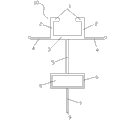
Fig. 1 is the structural representation of preferred embodiment of the present utility model;
Among the figure: 1, top board, 2, side plate, 3, base plate, 4, transverse plate, 5, first vertical panel, 6, base plate, 7, second vertical panel, 8, groove, 9, lattice framing, 10, stealthy suspention beam section bar.
The specific embodiment
In conjunction with the accompanying drawings and embodiments the utility model is described in further detail now, these accompanying drawings are the schematic diagram of simplification, basic structure of the present utility model only is described in a schematic way, so it only show the formation relevant with the utility model.
As shown in Figure 1, a kind of stealthy suspention beam section bar, along the profile length direction, diverse location has identical cross section, comprises two top boards 1 separated from one another, can move along the guide rail that is fixed on the roof along the biside plate 2 that extends under two top boards, 1 lateral, base plate 3, two top boards 1 that connect biside plate 2, the lower end of side plate 2 is outward extended with transverse plate 4, the lower end that the lower end of base plate 3 is connected with first vertical panel, 5, the first vertical panels 5 is connected with base plate 6, and the lower end of base plate 6 is connected with second vertical panel 7.
For fear of the landing of parts, the end perk obliquely of transverse plate 4.
For weight reduction, be convenient to operation, base plate 6 is provided with the groove 8 that the cross section is rectangle along its length.
The bottom of preferred second vertical panel 7 of the utility model is provided with lattice framing 9, and the both sides of lattice framing 9 are circular arc.
The preferred stealthy suspention beam section bar 10 of the utility model is processed easy, elegant in appearance along the central axis bilateral symmetry that is parallel to two top boards 1.
The preferred stealthy suspention beam section bar 10 of the utility model is aluminium alloy extrusions, and plasticity is good, and the intensity height has good corrosion stability.
Stealth of the present utility model is suspended beam section bar 10 in midair in use, and two top boards 1 are hooked on the guide rail of roof, and the two ends of base plate 6 snap in the groove of adjacent smallpox storehouse plate.
Above foundation desirable embodiment of the present utility model is enlightenment, and by above-mentioned description, the related personnel can carry out various change and modification fully in the scope that does not depart from this utility model technological thought.The technical scope of this utility model is not limited to the content on the manual, must determine technical scope according to the claim scope.

Claims (6)

1. the beam section bar is suspended in a stealth in midair, along the profile length direction, diverse location has identical cross section, it is characterized in that: comprise two top boards separated from one another, along the biside plate that extends under the two top board laterals, connect the base plate of biside plate, the lower end of described side plate is outward extended with transverse plate, the lower end of described base plate is connected with first vertical panel, and the lower end of described first vertical panel is connected with base plate, and the lower end of described base plate is connected with second vertical panel.
2. stealthy suspention beam section bar according to claim 1 is characterized in that: the end perk obliquely of described transverse plate.
3. the beam section bar is suspended in stealth according to claim 1 in midair, and it is characterized in that: described base plate is provided with the groove that the cross section is rectangle along its length.
4. the beam section bar is suspended in stealth according to claim 1 in midair, and it is characterized in that: the bottom of described second vertical panel is provided with lattice framing, and the both sides of described lattice framing are circular arc.
5. stealthy suspention beam section bar according to claim 1 is characterized in that: the described stealthy central axis bilateral symmetry that beam section bar edge is parallel to described two top boards of suspending in midair.
6. the beam section bar is suspended in stealth according to claim 1 in midair, it is characterized in that: described stealthy suspention beam section bar is aluminium alloy extrusions.
CN 201320074060 2013-02-17 2013-02-17 Invisible suspension beam section Expired - Lifetime CN203160498U (en)

Priority Applications (1)

Application Number Priority Date Filing Date Title
CN 201320074060 CN203160498U (en) 2013-02-17 2013-02-17 Invisible suspension beam section

Applications Claiming Priority (1)

Application Number Priority Date Filing Date Title
CN 201320074060 CN203160498U (en) 2013-02-17 2013-02-17 Invisible suspension beam section

Publications (1)

Publication Number Publication Date
CN203160498U true CN203160498U (en) 2013-08-28

Family

ID=49021693

Family Applications (1)

Application Number Title Priority Date Filing Date
CN 201320074060 Expired - Lifetime CN203160498U (en) 2013-02-17 2013-02-17 Invisible suspension beam section

Country Status (1)

Country Link
CN (1) CN203160498U (en)

Cited By (3)

* Cited by examiner, † Cited by third party
Publication number Priority date Publication date Assignee Title
CN107100310A (en) * 2017-06-15 2017-08-29 黑龙江施耐达建筑技术有限公司 The general erection support and mounting assembly of assembled open-type building bottom plate
CN110397171A (en) * 2019-05-28 2019-11-01 顾国平 Top plate connector and modularization top slab connecting structure
CN110397171B (en) * 2019-05-28 2024-04-26 索科(江苏)环境科技有限公司 Top plate connecting piece and modularized top plate connecting structure

Similar Documents

Publication Publication Date Title
CN203160498U (en) Invisible suspension beam section
CN202273339U (en) Curtain wallboard of suspension type curtain wall
CN203961090U (en) A kind of ceiling structure with angle steel conversion layer
CN202259336U (en) Guide-rail sectional material
CN203160499U (en) Suspension beam section bar
CN203878957U (en) Protective screen module unit
CN202187456U (en) Counteracting bearing suspended-ceiling suspension device
CN203684465U (en) Modularized assembled board wall
CN203361434U (en) Large-scale suspended ceiling structure with thin-wall metal plate
CN207484991U (en) A kind of glass curtain wall monorail hoisting structure
CN203296235U (en) Suspended ceiling conversion layer component of grid structure
CN201704839U (en) Practical novel ceiling system for corridor passageway
CN201433541Y (en) Color steel plate connecting beam
CN202273340U (en) Curtain wall plate for suspended curtain wall
CN202866613U (en) Wall space sunshade louver
CN204057561U (en) Hanging basket suspension hangs head
CN215626237U (en) Hanging crane rail mounting mechanism for net rack roof
CN211899157U (en) Energy-saving curtain wall for constructional engineering
CN203654536U (en) Installation fixture connecting piece of full glass curtain wall large-size glass panel
CN102381617A (en) Elevator straight beam bottom hanging structure
CN203878966U (en) Ascending and descending protecting screen of spine structure
CN203499070U (en) Back-bolt stone curtain wall
CN202414932U (en) Straight beam basement structure of elevator
CN203441045U (en) Push-pull stone external hanging bracket
CN219431097U (en) Buckle plate keel for connecting with suspension type wedge-shaped sliding lifting self-locking keel

Legal Events

Date Code Title Description
C14 Grant of patent or utility model
GR01 Patent grant
CB03 Change of inventor or designer information

Inventor after: Liang Jinli

Inventor before: Zhang Fenghe

COR Change of bibliographic data
CP03 Change of name, title or address

Address after: 215000 No.189, Shilin Road, Hushuguan Economic Development Zone, high tech Zone, Suzhou City, Jiangsu Province

Patentee after: Shenghui System Integration Group Co.,Ltd.

Address before: Shilin road high tech Zone Hushuguan Economic Development Zone of Suzhou city of Jiangsu Province, No. 189 215151

Patentee before: SHENG HUEI (SUZHOU) ENGINEERING CO.,LTD.

CX01 Expiry of patent term

Granted publication date: 20130828