CN203129828U - Lifting device for car window glass - Google Patents
Lifting device for car window glass Download PDFInfo
- Publication number
- CN203129828U CN203129828U CN2012207319993U CN201220731999U CN203129828U CN 203129828 U CN203129828 U CN 203129828U CN 2012207319993 U CN2012207319993 U CN 2012207319993U CN 201220731999 U CN201220731999 U CN 201220731999U CN 203129828 U CN203129828 U CN 203129828U
- Authority
- CN
- China
- Prior art keywords
- curled hair
- hair tube
- escapement
- wire rope
- riser guide
- Prior art date
- Legal status (The legal status is an assumption and is not a legal conclusion. Google has not performed a legal analysis and makes no representation as to the accuracy of the status listed.)
- Expired - Fee Related
Links
Images


Abstract
The utility model discloses a lifting device for a car window glass. The lifting device for the car window glass comprises a motor, a lifting guide rail, a sliding block assembly, a wire winding drum and a steel wire rope, wherein the sliding block assembly which is used for fixedly assembling the car window glass is arranged on the lifting guide rail, the wire winding drum is connected with an output shaft of the motor in a mechanical transmission mode, and the steel wire rope is wound on the wire winding drum. The wire winding drum is assembled in a wire winding drum housing. The steel wire rope extends out of the wire winding drum, stretches along the lifting guide rail, and is connected with the sliding block assembly, and therefore the wire winding drum can drive the sliding block assembly to move along the lifting guide rail in a drawing mode. A balance wheel and a torsional spring are arranged at the lower end of the lifting guide rail. Due to the facts that the wire winding drum housing can well protect the steel wire rope against corrosion so that the steel wire rope cannot easily be corroded, and the balance wheel and the torsional spring are used for enabling the steel wire rope to be always in a tensioning state, the phenomena of groove exceeding and dead clamping occurring in the wire winding drum after the steel wire rope loosens are prevented from happening.
Description
Technical field
The utility model relates to a kind of arrangements for automotive doors and operates control field, particularly a kind of window lifter assembly.
Background technology
Arrangements for automotive doors is the zone that the occupant gets on or off the bus and often operates, when the occupant is in car, need operations such as elevating glass ventilates, keeps off the rain, the glass lifting device is exactly that mechanism as the operation glass lifting is installed on the car door, is one of the mechanism of frequent operation of passenger.Along with development of technology, oneself generally adopts Motorized lift device to carry out the lifting of door-window at present.Notification number is that CN2150093Y China utility model patent discloses a kind of automobile door and window glass lifting device, the transmission ring that it mainly is made of motor-driven mechanism and sprocket wheel, chain, steel wire, fixed pulley, glass bracket is connected on two vertical edges of this transmission ring, drive whole transmission ring running by the motor-driven mechanism drive sprocket, two vertical edges of synchronous upper and lower motion drive the upper and lower motion of glass bracket, realize the lifting of glass.Because this technology power case adopts sprocket wheel and chain to transmit motor power, the chain internode of chain is asked the discontinuity that transmission ring is caused in the crack easily, causes producing in the glass lifting rocking; And the processing cost of sprocket wheel, chain is bigger, and is higher to space requirement, the glass bigger to curvature particularly, and its application is restricted.
And notification number to be the Chinese utility model patent of CN2160568Y disclose a kind of electrodynamic type window lifter assembly, its by motor-driven mechanism, be connected on the motor-driven mechanism the serving cylinder with two groups be folding and unfolding shape each other be wrapped on the serving cylinder and formed through the gentle rope of the traction institute that directive wheel is connected with glass bracket.Equivalent is twined and is discharged and draws gentle rope when utilizing the serving cylinder, realizes the parallel lifting of glass bracket.This technical scheme is improved the technical scheme of CN2150093Y.In this technical scheme, it uses the gentle rope of traction to carry out drawing and use flexible conduit and threaded adjusting pipe that the tension force that draws gentle rope is regulated to glass, has eliminated the deficiency of CN2150093Y technical scheme to a certain extent.But because the gentle rope of traction in use can produce certain stretcher strain, and this technical scheme adopts flexible conduit and threaded adjusting pipe that the tension force that draws gentle rope is regulated, need take door-window apart during adjusting, and can not when stretcher strain takes place the gentle rope of traction, in time compensate, influenced the stability of door-window glass lifting.
Fig. 1 has shown a kind of existing cable pulley type electric glass lifting device, this lifting gear is disclosed in No. the 201210179668.8th, the Chinese invention patent application of announcing on October 3rd, 2012, it comprises guide rail 1, be sleeved on the slide plate 2 on the guide rail 1, lay respectively at upper conductor wheel 6 and the lower wire wheel 7 at guide rail 1 two ends, spool 8, be wound on wire rope 5 and motor 9 on the spool 8, the two ends of wire rope 5 are walked around upper conductor wheel 6 and lower wire wheel 7 respectively and are connected with slide plate 2, also comprise the driving wheel 11 that is connected with motor 9 output shafts and the driven pulley 12 that meshes with driving wheel 11, spool 8 is connected with the output shaft of driven pulley 12.Motor 9, driving wheel 11 and driven pulley 12 are installed on the base 10, and base 10 is installed on the car door.During use, the automobile door glass of automobile is connected with slide plate 2, guide rail 1 is installed on the car door by upper bracket 3 and lower carriage 4, and wire rope 5 is wrapped on the spool 8, and is connected with slide plate 2 by upper conductor wheel 6 and lower wire wheel 8, during motor 9 rotations, drive driving wheel 11 rotations, driving wheel 11 and driven pulley 12 are by gear drive, and spool 8 is along with driven pulley 12 rotates together, make wire rope 5 haul slide plate 2 along guide rail 1 oscilaltion, thereby drive the automobile door glass oscilaltion.
Spool in the above-mentioned existing cable pulley type electric glass lifting device is not provided with the shade protective device; this makes that be wrapped in wire rope on the spool is easy to be subjected to immersing rainwater between the automobile door plate or the erosion of other corrosive liquid; cause the wire rope burn into to get rusty even rupture, influence the normal lifting of glass for vehicle window.In addition, should through long-time use the spacious situation of wire rope pine can appear by existing cable pulley type electric glass lifting device, cause wire rope in the curled hair tube that groove takes place more and then cause phenomenons such as lifting is stuck, influence the vehicle window opening and closing, cause maintenance, change the consumption on equal time and the expense, be unfavorable for promoting vehicle in the in the eyes of quality of client.
The utility model content
The purpose of this utility model is to provide a kind of window lifter assembly, can effectively protect the wire rope on the lifting gear to avoid corrosion appearance fracture.
Another purpose of the present utility model is to provide a kind of window lifter assembly, remains wire rope and be in tensioning state in the lifting gear use, avoids occurring wire rope pine and occurs in the curled hair tube more that groove causes the stuck phenomenon of lifting after spacious.
To achieve these goals, the utility model proposes following technical scheme.
A kind of window lifter assembly, the curled hair tube that it comprises motor, riser guide, be arranged on the riser guide slide block assembly in order to fixing assembling glass for vehicle window, be connected with mechanical drive mode with the output shaft of motor, and be wrapped in wire rope on the curled hair tube, thereby this wire rope stretches out to stretch and be connected with slide block assembly along riser guide from the curled hair tube and can affect slide block assembly to move along riser guide, this window lifter assembly also includes curled hair tube case, and aforementioned curled hair tube is assembled in this curled hair tube case.
Alternatively, in the technical solution of the utility model, this curled hair tube case and motor are fixed by mounting screw together and are assemblied on the support.
Alternatively, in the technical solution of the utility model, a side of this curled hair tube case is provided with receiving space in order to hold the curled hair tube, also is provided with the case central axis and uses with curled hair tube centre bore and match to assemble and locate the curled hair tube.
Alternatively, in the technical solution of the utility model, the upper end side of this curled hair tube case and lower end side are respectively arranged with first port of export and second port of export, so that the wire rope that is wrapped on the curled hair tube can stretch from curled hair tube case.
Alternatively, in the technical solution of the utility model, be provided with spring housing at first port of export place of this curled hair tube case and be assembled in helical spring on the spring housing.
Alternatively, in the technical solution of the utility model, this window lifter assembly also comprises an escapement, and this escapement is assemblied in by pivot pin and is adjacent to riser guide lower end position place and can rotates around this pivot pin.
Alternatively, in the technical solution of the utility model, this escapement profile is the cam configuration substantially, comprises the escapement body in cam master circle about the same and about the same in the escapement tensioned portion of cam part, and the center of escapement body offers the escapement axis hole and uses with pivot pin and match.
Alternatively, in the technical solution of the utility model, offer V-arrangement tensioning groove on the wheel rim side of the tensioned portion of this escapement, offer the escapement groove on the wheel rim side of escapement body, the wire rope that stretches out from second port of export of curled hair tube case tensioning groove and the escapement groove of walking around escapement of fitting successively extends along riser guide.
Alternatively, in the technical solution of the utility model, offer a torsion spring draw-in groove on the tensioned portion of this escapement, a torsion spring is wound and is installed on the pivot pin, first end of this torsion spring is fixed on the electric machine support, and second end of this torsion spring is fixedly installed in the torsion spring draw-in groove of escapement.
Alternatively, in the technical solution of the utility model, this window lifter assembly comprises the riser guide of pair of parallel, wherein the lower end of a riser guide is fixedly installed on the support with curled hair tube case and motor, the upper end of this support and this riser guide is installed on the door panel, and another riser guide then is installed on the door panel abreast.
Compared with prior art, the utility model utilizes curled hair tube case to protect wire rope not corroded easily well, prolongs application life and the part quality of wire rope; And, by the protection of curled hair tube case, can avoid after entering too much impurity in the lifting gear use, producing curled hair tube, wire rope and impurity friction and the lifter abnormal sound problem brought.In addition, utilize escapement and torsion spring to make wire rope be in the state of tensioning all the time, can not appear at and after wire rope relaxes in the curled hair tube the more stuck phenomenon of groove take place.
Description of drawings
Fig. 1 is a kind of stereogram of existing cable pulley type electric glass lifting device.
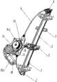
Fig. 2 is the stereogram of window lifter assembly of the present utility model.
Fig. 3 is the partial enlarged drawing of window lifter assembly shown in Figure 2.
Fig. 4 is the partial enlarged drawing after window lifter assembly shown in Figure 3 has been removed curled hair tube case.
Fig. 5 is the plan view of the curled hair tube case in the window lifter assembly of the present utility model.
Fig. 6 is the plan view of the escapement in the window lifter assembly of the present utility model.
Wherein, the label declaration among Fig. 2 to Fig. 6 is as follows.
The specific embodiment
Describe the specific embodiment of the present utility model in detail below in conjunction with accompanying drawing.
Understand easily, according to the technical solution of the utility model, do not changing under the connotation of the present utility model, but one of ordinary skill in the art can propose multiple frame mode and the implementation of mutual alternative.Therefore, the following specific embodiment and accompanying drawing only are the exemplary illustrations to the technical solution of the utility model, and should not be considered as of the present utility model all or be considered as restriction or restriction to technical solutions of the utility model.
Orientation terms such as the up, down, left, right, before and after of mentioning in this manual or may mentioning, front, the back side, top, bottom are to define with respect to the structure shown in each accompanying drawing, they are relative concepts, therefore might correspondingly change according to its diverse location of living in, different use state.So, these or other orientation term should be interpreted as restricted term yet.
See also Fig. 2 to shown in Figure 4, in an embodiment of technical solutions of the utility model, the curled hair tube 15 that window lifter assembly comprises motor 4, riser guide 13, be arranged on slide block assembly 11 on the riser guide 13, be connected with mechanical drive mode with the output shaft of motor 4, and be wrapped on the curled hair tube 15 and stretch and be connected with slide block assembly 11 and the wire rope 9 that can affect slide block assembly 11 to move along riser guide 13 along riser guide 15.This curled hair tube 15 is assembled in the curled hair tube case 1.As shown in Figure 2, in a preferred embodiment of the present utility model, window lifter assembly comprises riser guide 13a, the 13b of pair of parallel, respectively is provided with a slide block assembly 11 on each riser guide 13a, 13b, and glass for vehicle window 12 is fixedly installed on this slide block assembly 11.Wherein the lower end of a riser guide 13a is fixedly installed on the support 8 with curled hair tube case 1 and motor 4, be installed on the door panel (not shown) upper end of this support 8 and bar riser guide 13a, another riser guide 13b then is installed on the door panel (not shown) abreast, respectively be provided with a guide wheel 14 in the upper end of riser guide 13a and the upper/lower terminal of riser guide 13b, and the lower end of riser guide 13a is provided with an escapement 6.The downside from curled hair tube 15 that is wrapped in the wire rope 9 on the curled hair tube 15 stretches out and successively walks around the escapement 6 of riser guide 13a lower end and the guide wheel 14 of upper end successively, further successively walk around the guide wheel 14 of riser guide 13b lower end and upper end more successively, upside from curled hair tube 15 is wound up on the curled hair tube 15 then, thereby forms X-shaped intersection sealing fake between this is to parallel riser guide 13a, 13b.Wherein, between the guide wheel 14 of the guide wheel 14 on curled hair tube case 1, the riser guide 13a and riser guide 13b upper and lower end, wire rope 9 is arranged in the wire rope lining 91 of tubulose.
See also Fig. 3, Fig. 4, Fig. 5 and shown in Figure 6, by motor mounting screw 5, this curled hair tube case 1 and motor 4 are fixed together and are assemblied on the support 8.As shown in Figure 5, the profile of this curled hair tube case 1 is substantially close to trapezoidal or diamond configuration, its side (back side one side among Fig. 5) is provided with output shaft and the transmission mechanism (not shown) of receiving space in order to hold curled hair tube 15 and motor 4, and roughly the position is provided with case central axis 110 in the middle, uses with curled hair tube centre bore 150 and matches to assemble and locate curled hair tube 15.Edge distribution at this curled hair tube case 1 is provided with a plurality of screw holes 111, and screw 5 passes these screw holes 111 curled hair tube case 1 and motor 4 are fixed on the support 8.The upper end side of this curled hair tube case 1 and lower end side are respectively arranged with first port of export 112 and second port of export 113, can stretch from curled hair tube case 1 so that be wrapped in the curled hair groove 151 interior wire rope 9 of curled hair tube 15.See also Fig. 3 and shown in Figure 5, be provided with spring housing 2 at first port of export, 112 places of this curled hair tube case 1 and be assembled in helical spring 3 on the spring housing 2, the wire rope lining 91 that is enclosed within wire rope 9 outsides extends into this spring housing 2 and is fixed on wherein.
This enclosed curled hair tube case 1 can all be assemblied in the wire rope 9 that twines on curled hair tube 15 and the curled hair tube 15 in the airtight space; even be subjected to extraneous rainwater of invading at lifting gear, when the corrosion thing adheres to; can protect wire rope 9 not corroded easily well by means of this curled hair tube case 1, prolong application life and the part quality of wire rope.And, by the protection of curled hair tube case 1, can avoid after entering too much impurity in the lifting gear use, producing curled hair tube, wire rope and impurity friction and the lifter abnormal sound problem brought.
Shown among Fig. 3 and Fig. 4 that window lifter assembly also comprises an escapement 6 according to an embodiment of the present utility model.Be example with the lifting gear on the left front door of being assemblied in of showing among Fig. 3 and Fig. 4, this escapement 6 is assemblied in by pivot pin 7 and is adjacent to riser guide 13a lower end position place on the support 8, and can rotate around this pivot pin 7.As shown in Figure 6, escapement 6 profiles are the cam configuration substantially, it comprises the escapement body 61 in cam master circle about the same and about the same in the escapement tensioned portion 62 of cam part, wherein the center of escapement body 61 offers escapement axis hole 60, with matching with pivot pin 7 escapement 6 is assembled on the support 8, and further offers escapement groove 610 on the wheel rim side of escapement body 61.Offer a torsion spring draw-in groove 621 in this tensioned portion 62, and offer V-arrangement tensioning groove 620 in the wheel rim side of this tensioned portion 62.Torsion spring 10 is wound and is installed on the pivot pin 7, first end 101 of torsion spring 10 is in substantially parallel relationship to guide rail 13a from pivot pin 7 and extends out and be fixed in the torsion spring hole clipping 81 set on the support 8, and 102 at second end of torsion spring 10 extends out and is fixedly installed in the torsion spring draw-in groove 621 set on the escapement 6 from pivot pin 7.Like this, make the tensioned portion 62 of escapement 6 towards curled hair tube 15 directions, escapement 6 is in position shown in Figure 4 under the elastic force effect of torsion spring 10 and has the tendency that clockwise rotates around pivot pin 7.
As shown in Figure 3 and Figure 4, be example with the lifting gear that is assemblied on the left front door, tensioning groove 620 and escapement groove 610 that the wire rope 9 that stretches out from second port of export 113 of curled hair tube case 1 downside is fitted successively and walked around escapement 6 extend along riser guide 13a.When curled hair tube 15 turned clockwise under the drive of motor 4, wire rope 9 was affected along riser guide 13a among Fig. 2 to Fig. 4 by curled hair tube 15 and moves down, and the slide block assembly 11 that is fixedly connected on the wire rope 9 drives glass for vehicle window 12 declines; When curled hair tube 15 was rotated counterclockwise under the drive of motor 4, wire rope 9 was affected along riser guide 13a among Fig. 2 to Fig. 4 by curled hair tube 15 and moves up, and the slide block assembly 11 that is fixedly connected on the wire rope 9 drives glass for vehicle window 12 risings.
Be example with the lifting gear that is assemblied on the left front door still, when glass 12 rises to the top, the wire rope 9 of curled hair tube 15 lower end side is in relaxed state, and because escapement 6 has the tendency that clockwise rotates around pivot pin 7 under the elastic force effect of torsion spring 10, thereby escapement 6 rotates in the case, thereby the wire rope 9 in the tensioning groove 620 that is fitted in escapement is carried out tensioning under torsion spring 10 effects.When glass 12 dropped to the bottom, the wire rope 9 of curled hair tube 15 upper end side was in relaxed state, and may to the wire rope of upper end side carry out tensioning by spring housing 2 and spring 3 this moment.So just guarantee that wire rope 9 is in the state of tensioning all the time in whole runnings of glass lifting, can not appear at and after wire rope relaxes in the curled hair tube the more stuck phenomenon of groove take place, can effectively prolong application life and the part quality of glass-frame riser.
Claims (10)
1. window lifter assembly, it is characterized in that, it comprises motor, riser guide, be arranged on the described riser guide in order to the fixing slide block assembly that assembles glass for vehicle window, the curled hair tube that is connected with mechanical drive mode with the output shaft of described motor, and be wrapped in wire rope on the described curled hair tube, thereby described wire rope stretches out to stretch and be connected with described slide block assembly along described riser guide from described curled hair tube and can affect described slide block assembly to move along described riser guide, described window lifter assembly also includes curled hair tube case, and described curled hair tube is assembled in the described curled hair tube case.
2. window lifter assembly according to claim 1 is characterized in that, described curled hair tube case and described motor are fixed by mounting screw together and are assemblied on the support.
3. window lifter assembly according to claim 1, it is characterized in that, one side of described curled hair tube case is provided with receiving space in order to holding described curled hair tube, and it has the case central axis and uses and match to assemble and locate described curled hair tube with the centre bore of described curled hair tube.
4. window lifter assembly according to claim 1, it is characterized in that, the upper end side of described curled hair tube case and lower end side are respectively arranged with first port of export and second port of export, so that the wire rope that is wrapped on the described curled hair tube can stretch from described curled hair tube case.
5. window lifter assembly according to claim 4 is characterized in that, is provided with spring housing at first port of export place of described curled hair tube case and is assembled in helical spring on the spring housing.
6. according to each described window lifter assembly in the claim 1 to 5, it is characterized in that it further comprises an escapement, described escapement is assemblied in by pivot pin and is adjacent to described riser guide lower end position place and can rotates around described pivot pin.
7. window lifter assembly according to claim 6, it is characterized in that, described escapement profile is the cam configuration substantially, comprise the escapement body in cam master circle about the same and about the same in the tensioned portion of cam part, the center of described escapement body offers the escapement axis hole and uses with described pivot pin and match.
8. window lifter assembly according to claim 7, it is characterized in that, offer V-arrangement tensioning groove on the wheel rim side of the tensioned portion of described escapement, offer the escapement groove on the wheel rim side of described escapement body, the wire rope that stretches out from described curled hair tube case is fitted successively and is walked around described tensioning groove and the escapement groove extends along described riser guide.
9. window lifter assembly according to claim 8, it is characterized in that, offer a torsion spring draw-in groove on the tensioned portion of described escapement, a torsion spring is wound and is installed on the pivot pin, first end of described torsion spring is fixed on the electric machine support, and second end of described torsion spring is fixedly installed in the described torsion spring draw-in groove.
10. window lifter assembly according to claim 1, it is characterized in that, described window lifter assembly comprises the riser guide of pair of parallel, wherein the lower end of a riser guide is fixedly installed on the support with described curled hair tube case and described motor, be installed on the door panel upper end of described support and this riser guide, and another riser guide then is installed on the door panel abreast.
Priority Applications (1)
| Application Number | Priority Date | Filing Date | Title |
|---|---|---|---|
| CN2012207319993U CN203129828U (en) | 2012-12-27 | 2012-12-27 | Lifting device for car window glass |
Applications Claiming Priority (1)
| Application Number | Priority Date | Filing Date | Title |
|---|---|---|---|
| CN2012207319993U CN203129828U (en) | 2012-12-27 | 2012-12-27 | Lifting device for car window glass |
Publications (1)
| Publication Number | Publication Date |
|---|---|
| CN203129828U true CN203129828U (en) | 2013-08-14 |
Family
ID=48937820
Family Applications (1)
| Application Number | Title | Priority Date | Filing Date |
|---|---|---|---|
| CN2012207319993U Expired - Fee Related CN203129828U (en) | 2012-12-27 | 2012-12-27 | Lifting device for car window glass |
Country Status (1)
| Country | Link |
|---|---|
| CN (1) | CN203129828U (en) |
Cited By (10)
| Publication number | Priority date | Publication date | Assignee | Title |
|---|---|---|---|---|
| CN104533216A (en) * | 2015-02-04 | 2015-04-22 | 陈学琴 | Toothed belt lift type lifter |
| CN104563704A (en) * | 2015-02-04 | 2015-04-29 | 陈学琴 | Tooth belt pull type self-adaptive slide block lifter with clip buffer gear |
| CN104594750A (en) * | 2015-02-04 | 2015-05-06 | 陈学琴 | Toothed belt pulling type self-adaptive sliding block lifter |
| CN104612523A (en) * | 2015-02-04 | 2015-05-13 | 陈学琴 | Tooth-belt-lifting type spring buffering gear lifter |
| CN104746994A (en) * | 2015-02-04 | 2015-07-01 | 陈学琴 | Toothed belt lifting-and-pulling type buffer gear lifter |
| CN104746988A (en) * | 2015-03-10 | 2015-07-01 | 陈学琴 | Self-adaptive sliding block lifter of toothed belt pulling-and-lifting type buffer gear |
| CN104746989A (en) * | 2015-02-04 | 2015-07-01 | 陈学琴 | Hole-belt-type elastic piece buffering gear self-adaptation sliding block lifter |
| CN104746990A (en) * | 2015-02-04 | 2015-07-01 | 陈学琴 | Hole-belt-type buffering gear self-adaptation sliding block lifter. |
| CN104763275A (en) * | 2015-02-04 | 2015-07-08 | 陈学琴 | Toothed belt lift type spring buffer gear adaptive slide block hoist |
| CN109642447A (en) * | 2016-08-17 | 2019-04-16 | 布罗泽汽车部件制造班贝克有限公司 | Equipment for tensioning rope transmission device-window lifter Bowden cable |
-
2012
- 2012-12-27 CN CN2012207319993U patent/CN203129828U/en not_active Expired - Fee Related
Cited By (12)
| Publication number | Priority date | Publication date | Assignee | Title |
|---|---|---|---|---|
| CN104533216A (en) * | 2015-02-04 | 2015-04-22 | 陈学琴 | Toothed belt lift type lifter |
| CN104563704A (en) * | 2015-02-04 | 2015-04-29 | 陈学琴 | Tooth belt pull type self-adaptive slide block lifter with clip buffer gear |
| CN104594750A (en) * | 2015-02-04 | 2015-05-06 | 陈学琴 | Toothed belt pulling type self-adaptive sliding block lifter |
| CN104612523A (en) * | 2015-02-04 | 2015-05-13 | 陈学琴 | Tooth-belt-lifting type spring buffering gear lifter |
| CN104746994A (en) * | 2015-02-04 | 2015-07-01 | 陈学琴 | Toothed belt lifting-and-pulling type buffer gear lifter |
| CN104746989A (en) * | 2015-02-04 | 2015-07-01 | 陈学琴 | Hole-belt-type elastic piece buffering gear self-adaptation sliding block lifter |
| CN104746990A (en) * | 2015-02-04 | 2015-07-01 | 陈学琴 | Hole-belt-type buffering gear self-adaptation sliding block lifter. |
| CN104763275A (en) * | 2015-02-04 | 2015-07-08 | 陈学琴 | Toothed belt lift type spring buffer gear adaptive slide block hoist |
| CN104746988A (en) * | 2015-03-10 | 2015-07-01 | 陈学琴 | Self-adaptive sliding block lifter of toothed belt pulling-and-lifting type buffer gear |
| CN109642447A (en) * | 2016-08-17 | 2019-04-16 | 布罗泽汽车部件制造班贝克有限公司 | Equipment for tensioning rope transmission device-window lifter Bowden cable |
| CN109642447B (en) * | 2016-08-17 | 2020-06-19 | 布罗泽汽车部件制造班贝克有限公司 | Device for tensioning a bowden cable of a cable drive window lifter |
| US11326382B2 (en) | 2016-08-17 | 2022-05-10 | Brose Fahrzeugteile Gmbh & Co. Kommanditgesellschaft, Bamberg | Device for tensioning a Bowden cable of a cable-operated window lifter |
Similar Documents
| Publication | Publication Date | Title |
|---|---|---|
| CN203129828U (en) | Lifting device for car window glass | |
| CN103890300B (en) | Window regulator | |
| ATE504464T1 (en) | OPENING AND CLOSING DEVICE FOR MOTOR VEHICLE SLIDING DOORS | |
| CN102980759A (en) | Tester for automotive tail door | |
| CN110939344B (en) | Opening and closing mechanism of drifting window | |
| CN203069358U (en) | Automobile trunk cover test apparatus | |
| CN203223096U (en) | Transmission structure of electric sliding door | |
| DK2446102T3 (en) | GATE WITH A DRIVE SYSTEM | |
| CN201874385U (en) | Rope wheel type glass lifter | |
| CN104100197B (en) | Suspension translation door | |
| CN201262008Y (en) | Rope wheel type window lifter | |
| CN104203794A (en) | Elevator car door drive mechanism | |
| CN209687176U (en) | A kind of external controller formula Anti-pinch glass lifting device | |
| CN201777317U (en) | Automotive spare tire lifter | |
| CN210022907U (en) | Three-dimensional sorting device of floating independent power unit | |
| CN106930643A (en) | A kind of parallel-moving type automatically turns on antitheft door | |
| CN101597998B (en) | High-stability electric soft roller shutter door | |
| CN202847824U (en) | Starting device of engine cover lock and automobile | |
| CN204571641U (en) | A kind of structure improving automobile door and window lifter reliability | |
| WO2010085126A3 (en) | Automatic arrangement device for fiber optics | |
| KR100726268B1 (en) | Sunshade apparatus for automobile | |
| CN104712210B (en) | Method and structure for improving reliability of car door and window lifter | |
| CN211039561U (en) | Suspension driving device for pedestrian remote control trolley | |
| CN201502297U (en) | High-stability electric flexible rolling door | |
| CN201062762Y (en) | Guiding type CMY device for mixing color |
Legal Events
| Date | Code | Title | Description |
|---|---|---|---|
| C14 | Grant of patent or utility model | ||
| GR01 | Patent grant | ||
| CF01 | Termination of patent right due to non-payment of annual fee |
Granted publication date: 20130814 Termination date: 20201227 |
|
| CF01 | Termination of patent right due to non-payment of annual fee |