CN203115671U - Direct type backlight module - Google Patents
Direct type backlight module Download PDFInfo
- Publication number
- CN203115671U CN203115671U CN2012206754827U CN201220675482U CN203115671U CN 203115671 U CN203115671 U CN 203115671U CN 2012206754827 U CN2012206754827 U CN 2012206754827U CN 201220675482 U CN201220675482 U CN 201220675482U CN 203115671 U CN203115671 U CN 203115671U
- Authority
- CN
- China
- Prior art keywords
- direct type
- mode set
- backlight module
- type backlight
- straight aphototropism
- Prior art date
- Legal status (The legal status is an assumption and is not a legal conclusion. Google has not performed a legal analysis and makes no representation as to the accuracy of the status listed.)
- Expired - Fee Related
Links
- 230000005142 aphototropism Effects 0.000 claims description 18
- 239000004973 liquid crystal related substance Substances 0.000 abstract description 8
- 230000000007 visual effect Effects 0.000 abstract description 3
- 238000009792 diffusion process Methods 0.000 abstract description 2
- 238000005516 engineering process Methods 0.000 description 3
- 238000006243 chemical reaction Methods 0.000 description 2
- 238000004519 manufacturing process Methods 0.000 description 2
- 238000000034 method Methods 0.000 description 2
- 241001316290 Gypsophila Species 0.000 description 1
- 230000007812 deficiency Effects 0.000 description 1
- 238000010586 diagram Methods 0.000 description 1
- 230000000694 effects Effects 0.000 description 1
- 238000005286 illumination Methods 0.000 description 1
- 230000003287 optical effect Effects 0.000 description 1
- 238000005728 strengthening Methods 0.000 description 1
- 238000006467 substitution reaction Methods 0.000 description 1
Images
Abstract
The utility model discloses a direct type backlight module. The direct type backlight module is provided with a rear shell, a middle shell, a plurality of radiating fins, a plurality of light bars, a reflecting sheet, a diffusion plate, a diaphragm, a middle-frame bracket and a front shell which are arranged from bottom to top in sequence; and the reflecting sheet is provided with a sharp-angle structure and a slope structure. The direct type backlight module disclosed by the utility model has the advantages that the light mixing distance in a direct type liquid-crystal module is reduced, and under the condition of ensuring the specification parameters such as brightness, uniformity and visual angle, the reduction of the thickness of the whole machine is realized by reducing the light mixing distance, so that the appearance is more attractive, and further the advantage and the competitiveness of the direct type liquid-crystal module are also enhanced.
Description
Technical field
The utility model relates to field of liquid crystal display, in particular a kind of down straight aphototropism mode set.
Background technology
LED LCD TV product has better color effect because of it in recent years, thinner design with and the characteristics of energy-conserving and environment-protective make the LED product become main product in the LCD TV gradually, and progressively to have eliminated with CCFL be LCD product backlight.Along with the extensive application to the LED lamp of several big producer of the wide-scale adoption LED lamp of illumination industry in recent years and colour TV, and this further adjustment on price and performance of LED lamp, the cost of LED LCD TV is also more and more lower, the LED product is also gradually from the high-end middle-end of moving towards, and the LED LCD TV also must occupy the bigger market share.Also be market trend with straight-down negative LED products substitution CCFL series of products.But because of reasons such as technology and the levels of production, direct-type backlight is generally thicker: need long light mixing distance, can't accomplish thinner.
At present, the directly-down liquid crystal module in the market realizes that evenly mixed light mainly is by following several modes:
First kind, adopt the mode of babysbreath, the lamp of the more LED that arranges;
Second kind, add optical lens at LED and realize arranging with less LED lamp and less lamp bar;
The third, adopt the method for printing net-point on diffuser plate, realize low light mixing distance and more uniform output backlight by the diffuser plate that is printed on the site.
All there is certain weak point in it:
Adopting first kind of mode is the more LED of arranging lamp, problems such as cost, reliability, manufacturing can occur;
It is higher to add the present lens cost of lens, pastes difficulty of lens technologies, and the matching of lens and LED is relatively poor;
Adopt the diffuser plate site design of printing net-point difficult, the luminance loss is bigger, and the more diaphragm of needs goes to cover the site and a kind of LED scheme can only be mated in every edition site, and versatility is relatively poor.
Therefore, prior art has yet to be improved and developed.
The utility model content
In view of above-mentioned the deficiencies in the prior art, the purpose of this utility model is to provide a kind of down straight aphototropism mode set, and direct-type backlight needs long light mixing distance in the solution prior art, and is generally thicker, can't realize the problem of superthin structure.
In order to achieve the above object, the utility model has been taked following technical scheme:
A kind of down straight aphototropism mode set wherein, is disposed with back cover, mesochite, several fin, several lamp bars corresponding with fin, reflector plate, diffuser plate, diaphragm, middle frame bracket and fore shell from the bottom to top; Described reflector plate is provided with horn structure and ramp structure.
Described down straight aphototropism mode set, wherein, the number of described lamp bar is two.
Described down straight aphototropism mode set, wherein, described horn structure is arranged on the middle part of reflector plate, and ramp structure is arranged on the both sides of horn structure.
Described side light type back light module assembly structure, wherein, described diffuser plate lower surface is provided with part reflective semitransparent film.
Compared to prior art, the down straight aphototropism mode set that the utility model provides, directly-down liquid crystal module internal light mixing distance is dwindled, guaranteeing brightness, under the situation of specification parameter such as uniformity and visual angle, thereby realize reducing complete machine thickness by reducing light mixing distance, so that outward appearance is more attractive in appearance, also further strengthened advantage and the competitiveness of directly-down liquid crystal module.
Description of drawings
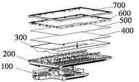
Fig. 1 is the decomposing schematic representation of the down straight aphototropism mode set that provides of the utility model embodiment.
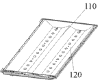
Fig. 2 is the schematic diagram of reflector plate in the down straight aphototropism mode set that provides of the utility model embodiment.
The specific embodiment
The utility model provides a kind of down straight aphototropism mode set.For making the purpose of this utility model, technical scheme and advantage clearer, clear and definite, below further describe with reference to the accompanying drawing the utility model of embodiment that develops simultaneously.
The down straight aphototropism mode set that the utility model enforcement provides, as shown in Figure 1, described down straight aphototropism mode set is disposed with back cover 100, mesochite 200, several fin, several lamp bars corresponding with fin, reflector plate 300, diffuser plate 400, diaphragm 500, middle frame bracket 600 and fore shell 700 from the bottom to top; Described reflector plate is provided with horn structure and ramp structure.
Specifically, back cover, mesochite are fastened togather, fin and lamp bar correspondence are arranged on the inside of down straight aphototropism mode set, the light that the lamp bar sends is by the structure (horn structure and ramp structure) of reflector plate, and the diffusion of process diffuser plate, evenly inject on the described diaphragm, by further strengthening its brightness and uniformity behind the diaphragm, realized the even output of light.Lay parts such as movement power panel and loudspeaker between back cover and the mesochite, fin and lamp bar are installed earlier on the mesochite, then reflector plate is put, put diffuser plate again, diaphragm, middle frame bracket is put PCBI on the middle frame bracket, then with the fixing PCBI of fore shell.
The application's key is that as shown in Figure 2, described reflector plate has horn structure 110 and ramp structure 120, is implemented in the even output in the less light mixing distance.In the present embodiment, described horn structure 110 is arranged on the middle part of reflector plate, and ramp structure 120 is arranged on the both sides of horn structure 110.
Further, described LED lamp bar is band lens lamp bar, only need 2 lamp bars can realize even output in this design, and present direct-type backlight is the even output that is implemented in the less light mixing distance, and major part is 3 could realize with more than the lamp bar.
Further, described diffuser plate lower surface is provided with part reflective semitransparent film.Described part reflective semitransparent film places the diffuser plate lower surface to fit with it, by the structure of reflector plate, realizes that light is able to even output so that light is realized the reflection mixed light in cavity in less mixed light scope.
In sum, the application's down straight aphototropism mode set wherein, is disposed with back cover, mesochite, several fin, several lamp bars corresponding with fin, reflector plate, diffuser plate, diaphragm, middle frame bracket and fore shell from the bottom to top; Described reflector plate is provided with horn structure and ramp structure.Thereby directly-down liquid crystal module internal light mixing distance is dwindled, guaranteeing brightness, under the situation of specification parameter such as uniformity and visual angle, thereby realize reducing complete machine thickness by reducing light mixing distance, so that outward appearance is more attractive in appearance, also further strengthened advantage and the competitiveness of directly-down liquid crystal module.
Should be understood that; application of the present utility model is not limited to above-mentioned giving an example; for those of ordinary skills, can be improved according to the above description or conversion, all these improvement and conversion all should belong to the protection domain of the utility model claims.
Claims (4)
1. a down straight aphototropism mode set is characterized in that, is disposed with back cover, mesochite, several fin, several lamp bars corresponding with fin, reflector plate, diffuser plate, diaphragm, middle frame bracket and fore shell from the bottom to top; Described reflector plate is provided with horn structure and ramp structure.
2. down straight aphototropism mode set according to claim 1 is characterized in that, the number of described lamp bar is two.
3. down straight aphototropism mode set according to claim 1 is characterized in that, described horn structure is arranged on the middle part of reflector plate, and ramp structure is arranged on the both sides of horn structure.
4. down straight aphototropism mode set according to claim 1 is characterized in that, described diffuser plate lower surface is provided with part reflective semitransparent film.
Priority Applications (1)
| Application Number | Priority Date | Filing Date | Title |
|---|---|---|---|
| CN2012206754827U CN203115671U (en) | 2012-12-10 | 2012-12-10 | Direct type backlight module |
Applications Claiming Priority (1)
| Application Number | Priority Date | Filing Date | Title |
|---|---|---|---|
| CN2012206754827U CN203115671U (en) | 2012-12-10 | 2012-12-10 | Direct type backlight module |
Publications (1)
| Publication Number | Publication Date |
|---|---|
| CN203115671U true CN203115671U (en) | 2013-08-07 |
Family
ID=48896012
Family Applications (1)
| Application Number | Title | Priority Date | Filing Date |
|---|---|---|---|
| CN2012206754827U Expired - Fee Related CN203115671U (en) | 2012-12-10 | 2012-12-10 | Direct type backlight module |
Country Status (1)
| Country | Link |
|---|---|
| CN (1) | CN203115671U (en) |
Cited By (2)
| Publication number | Priority date | Publication date | Assignee | Title |
|---|---|---|---|---|
| CN104089223A (en) * | 2014-07-10 | 2014-10-08 | 京东方科技集团股份有限公司 | Backlight optical system and display device |
| CN110296356A (en) * | 2018-03-22 | 2019-10-01 | 深圳市海洋王照明工程有限公司 | Illuminator |
-
2012
- 2012-12-10 CN CN2012206754827U patent/CN203115671U/en not_active Expired - Fee Related
Cited By (4)
| Publication number | Priority date | Publication date | Assignee | Title |
|---|---|---|---|---|
| CN104089223A (en) * | 2014-07-10 | 2014-10-08 | 京东方科技集团股份有限公司 | Backlight optical system and display device |
| CN104089223B (en) * | 2014-07-10 | 2017-01-18 | 京东方科技集团股份有限公司 | Backlight optical system and display device |
| CN110296356A (en) * | 2018-03-22 | 2019-10-01 | 深圳市海洋王照明工程有限公司 | Illuminator |
| CN110296356B (en) * | 2018-03-22 | 2021-08-13 | 深圳市海洋王照明工程有限公司 | Lighting lamp |
Similar Documents
| Publication | Publication Date | Title |
|---|---|---|
| CN102767762B (en) | Backlight module | |
| CN109116621A (en) | Display module and display device | |
| CN103901654B (en) | The mounting structure of optical diaphragm group | |
| CN103775923B (en) | Lamp bar and the backlight module with this lamp bar | |
| CN105572784A (en) | Light guide plate, and backlight unit and display device including the same | |
| CN103032762A (en) | Backlight module and display module | |
| CN210514884U (en) | Light emitting diode lamp strip, backlight module and display device | |
| CN209946442U (en) | Light guide plate with notch at through hole, backlight module and display device | |
| CN201606740U (en) | LED side backlight module, LCD (liquid crystal display) device and LCD TV | |
| CN204879661U (en) | Backlight unit and liquid crystal display panel | |
| CN204925560U (en) | Hi -lite LCD module | |
| CN103676318A (en) | Backlight structure of liquid crystal display television | |
| CN203115671U (en) | Direct type backlight module | |
| CN205318064U (en) | Backlight module and display device | |
| WO2020062717A1 (en) | Display device | |
| CN203363863U (en) | Straight down type backlight module and display device | |
| CN109725464B (en) | Straight-lower side-in combined liquid crystal module backlight display device | |
| CN105158970B (en) | A kind of backlight module and display panel | |
| CN111880337A (en) | Backlight assembly and liquid crystal display module | |
| CN101418917A (en) | Backlight module structure and display device thereof | |
| CN207571434U (en) | Back light and display device | |
| CN201788335U (en) | Direct-type liquid crystal module using high-power LED as light source | |
| CN205880445U (en) | Back light module and liquid crystal display device | |
| CN210864276U (en) | Direct type display device lamp panel component avoiding structure | |
| CN205450512U (en) | Reflector plate for backlight unit |
Legal Events
| Date | Code | Title | Description |
|---|---|---|---|
| C14 | Grant of patent or utility model | ||
| GR01 | Patent grant | ||
| CF01 | Termination of patent right due to non-payment of annual fee |
Granted publication date: 20130807 Termination date: 20151210 |
|
| EXPY | Termination of patent right or utility model |