CN203103740U - High-speed cam vertical insertion terminal machine - Google Patents
High-speed cam vertical insertion terminal machine Download PDFInfo
- Publication number
- CN203103740U CN203103740U CN 201220688013 CN201220688013U CN203103740U CN 203103740 U CN203103740 U CN 203103740U CN 201220688013 CN201220688013 CN 201220688013 CN 201220688013 U CN201220688013 U CN 201220688013U CN 203103740 U CN203103740 U CN 203103740U
- Authority
- CN
- China
- Prior art keywords
- terminal
- cam
- end device
- sending end
- sending
- Prior art date
- Legal status (The legal status is an assumption and is not a legal conclusion. Google has not performed a legal analysis and makes no representation as to the accuracy of the status listed.)
- Expired - Fee Related
Links
Images

Landscapes
- Manufacturing Of Electrical Connectors (AREA)
Abstract
The utility model relates to the technical field of electronic product assembling equipment, and especially relates to a high-speed cam vertical insertion terminal machine, comprising a base, and the base is provided with a sending end device, a clamping end device, a cutting end device, a cam shaft rotatably connected on the base, and a drive device driving rotation of the cam shaft. The sending end device and the clamping end device are respectively jointed with the cutting end device. The cam shaft is sleeved and connected with cutting end cam, a sending end cam, and a clamping end cam. The cutting end device is connected with the cutting end cam. The sending end device is connected with the sending end cam. The clamping end device is connected with the clamping end cam. The terminal machine uses irregular circling motion of the cams to respectively drive the sending end device to deliver terminals, the clamping end device to clamp the terminals, and the cutting end device to cut the terminals and insert the terminals, thereby realizing continuous and automatic terminal sending, terminal clamping, terminal cutting, and terminal inserting. Thus, reciprocating motion reduces handwork and labor forces, production efficiency and production are greatly increased, cost is reduced, and time is saved.
Description
Technical field:
The utility model relates to electronic product mounting equipment technical field, refers in particular to the vertical spigot handset of High speed cam.
Background technology:
At present, in the processing of terminal part, generally fracture by manual, insert in the plastic cement by hand then, realize whole shaping with tool again, operating efficiency is lower, quality is difficult to control, in the course of processing, terminal inserts phenomenons such as appearance easily is out of shape, foreign matter is sneaked into, thereby cause defective products, and the time and the operation of processing are all longer, have had a strong impact on cost performance of product, influence the production capacity that product lot quantity is produced, traditional handwork has defectives such as efficient is low, quality is unstable, the making space requirement is big, serious waste of resources.And at present, existing terminal machining machine and tool has the few and not high defective of machining accuracy of function, in use has significant limitation.
The utility model content:
The purpose of this utility model is exactly the deficiency that exists at prior art and provide a kind of cam that utilizes to do the vertical spigot handset of High speed cam that irregular circular motion is realized automatic sending end, folder terminal, cut out terminal and spigot, working (machining) efficiency is high.
To achieve these goals, the technical solution adopted in the utility model is: the vertical spigot handset of High speed cam, include pedestal, pedestal is provided with the sending end device that is used to carry terminal, be used to press from both sides the folder end device of terminal, the sanction end device that is used for severing terminal and spigot, be rotatably connected on the camshaft on the pedestal, the drive unit that drive cam shaft is rotated, sending end device and folder end device are connected with the sanction end device respectively, be socketed with the sanction end cam on the camshaft, the sending end cam, the folder end cam, cutting out end device is connected with the sanction end cam, the sending end device is connected with the sending end cam, and the folder end device is connected with the folder end cam.
Described drive unit is a servomotor, and the output of drive unit drives by synchronous pulley mechanism and connects camshaft.
The sending end push rod that the terminal that described sending end device includes the sending end track that is used for passing through for terminal, promote the sending end track advances, be slidingly connected at sliding substrate on the pedestal, promote the sending end connecting rod that sliding substrate slides, the sending end track is arranged on the pedestal, the sanction end device is positioned at the discharging opening place of sending end track, the sending end connecting rod is connected with sending end cam, sliding substrate respectively, and the sending end push rod is fixed on the sliding substrate.
Described folder end device includes the terminal briquetting that is used to clamp terminal, promote the terminal briquetting to cutting out the folder end link that end device moves, and the terminal briquetting slides and is provided with on the pedestal near the position of cutting out end device, and the folder end link is connected with folder end cam, terminal briquetting respectively.
Described sanction end device includes the terminal cutting knife that is used for severing terminal and spigot, the sanction end link that promotion terminal cutting knife moves, and the terminal cutting knife vertically is slidingly connected on the pedestal, cuts out end link and is connected with sanction end cam, terminal cutting knife respectively.
The utility model beneficial effect is: the vertical spigot handset of the High speed cam that the utility model provides, it includes pedestal, pedestal is provided with the sending end device that is used to carry terminal, be used to press from both sides the folder end device of terminal, the sanction end device that is used for severing terminal and spigot, be rotatably connected on the camshaft on the pedestal, the drive unit that drive cam shaft is rotated, sending end device and folder end device are connected with the sanction end device respectively, be socketed with the sanction end cam on the camshaft, the sending end cam, the folder end cam, cutting out end device is connected with the sanction end cam, the sending end device is connected with the sending end cam, the folder end device is connected with the folder end cam, the utility model utilizes cam to do irregular circular motion, drive the sending end device respectively and carry terminal, folder end device folder terminal, cut out end device severing terminal and spigot, realize continuously automatic sending end, the folder terminal, cut out terminal and spigot, motion and so forth, craft and labour have been reduced, improve production efficiency and output greatly, reduced cost, saved the time.
Description of drawings:
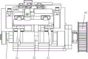
Fig. 1 is a structural representation of the present utility model.
Fig. 2 is a front view of the present utility model.
Embodiment:
Below in conjunction with accompanying drawing the utility model is further described, see shown in Fig. 1 ~ 2, the utility model includes pedestal 1, pedestal 1 is provided with the sending end device 2 that is used to carry terminal, be used to press from both sides the folder end device 3 of terminal, the sanction end device 4 that is used for severing terminal and spigot, be rotatably connected on the camshaft 5 on the pedestal 1, the drive unit 6 that drive cam shaft 5 is rotated, sending end device 2 and folder end device 3 are connected with sanction end device 4 respectively, be socketed with on the camshaft 5 and cut out end cam 51, sending end cam 52, folder end cam 53, cutting out end device 4 is connected with sanction end cam 51, sending end device 2 is connected with sending end cam 52, and folder end device 3 is connected with folder end cam 53.
Drive unit 6 is a servomotor, and the output of drive unit 6 drives by synchronous pulley mechanism 61 and connects camshaft 5, control precision height.
Sending end device 2 includes and is used for the sending end track 21 that the confession terminal passes through, promote the sending end push rod 22 that the terminal in the sending end track 21 advances, be slidingly connected at the sliding substrate 23 on the pedestal 1, promote the sending end connecting rod 24 that sliding substrate 23 slides, sending end track 21 is arranged on the pedestal 1, sanction end device 4 is positioned at the discharging opening place of sending end track 21, sending end connecting rod 24 respectively with sending end cam 52, sliding substrate 23 connects, sending end push rod 22 is fixed on the sliding substrate 23, sending end connecting rod 24 drives sliding substrate 23 intermittent front and back and slides under the effect of sending end cam 52, drive the terminal that sending end push rod 22 intermittently promotes in the sending end track 21 simultaneously and advance, realize automatic sending end.
Cut out end device 4 and include the terminal cutting knife 41 that is used for severing terminal and spigot, the sanction end link 42 that promotion terminal cutting knife 41 moves, terminal cutting knife 41 vertically is slidingly connected on the pedestal 1, cutting out end link 42 is connected with sanction end cam 51, terminal cutting knife 41 respectively, cutting out end link 42 drive terminal cutting knife 41 intermittences under the effect of cutting out end cam 51 slides up and down, intermittently severing is by the terminal and spigot of 3 clampings of folder end device to make terminal cutting knife 41, and terminal and spigot are cut out in realization automatically.
The utility model utilization sanction end cam 51, sending end cam 52, folder end cam 53 are done irregular circular motion, driving sending end device 2 respectively synchronously carries terminal, folder end device 3 folder terminals, cuts out end device 4 severing terminals and spigot, realize continuously automatic sending end, folder terminal, cut out terminal and spigot, motion and so forth, craft and labour have been reduced, improve production efficiency and output greatly, reduced cost, saved the time.The sub-speed of the utility model spigot can reach 1200 rev/mins, is applicable to the vertical spigot handset of connector automatic high-speed tool equipment.
Certainly, the above only is a better embodiment of the present utility model, so all equivalences of doing according to the described structure of the utility model patent claim, feature and principle change or modify, is included in the utility model patent claim.
Claims (5)
1. the vertical spigot handset of High speed cam, it includes pedestal (1), it is characterized in that: described pedestal (1) is provided with the sending end device (2) that is used to carry terminal, be used to press from both sides the folder end device (3) of terminal, the sanction end device (4) that is used for severing terminal and spigot, be rotatably connected on the camshaft (5) on the pedestal (1), the drive unit (6) that drive cam shaft (5) is rotated, sending end device (2) and folder end device (3) are connected with sanction end device (4) respectively, be socketed with on the camshaft (5) and cut out end cam (51), sending end cam (52), folder end cam (53), cutting out end device (4) is connected with sanction end cam (51), sending end device (2) is connected with sending end cam (52), and folder end device (3) is connected with folder end cam (53).
2. the vertical spigot handset of High speed cam according to claim 1 is characterized in that: described drive unit (6) is a servomotor, and the output of drive unit (6) drives by synchronous pulley mechanism (61) and connects camshaft (5).
3. the vertical spigot handset of High speed cam according to claim 1, it is characterized in that: described sending end device (2) includes and is used for the sending end track (21) that the confession terminal passes through, promote the sending end push rod (22) that the terminal in the sending end track (21) advances, be slidingly connected at the sliding substrate (23) on the pedestal (1), promote the sending end connecting rod (24) that sliding substrate (23) slides, sending end track (21) is arranged on the pedestal (1), sanction end device (4) is positioned at the discharging opening place of sending end track (21), sending end connecting rod (24) respectively with sending end cam (52), sliding substrate (23) connects, and sending end push rod (22) is fixed on the sliding substrate (23).
4. the vertical spigot handset of High speed cam according to claim 1, it is characterized in that: described folder end device (3) includes the terminal briquetting (31) that is used to clamp terminal, the folder end link (32) that promotion terminal briquetting (31) moves to sanction end device (4), terminal briquetting (31) slides the position that pedestal (1) is gone up close sanction end device (4) is set, and folder end link (32) is connected with folder end cam (53), terminal briquetting (31) respectively.
5. according to the vertical spigot handset of any described High speed cam of claim 1 ~ 4, it is characterized in that: described sanction end device (4) includes the terminal cutting knife (41) that is used for severing terminal and spigot, the sanction end link (42) that promotion terminal cutting knife (41) moves, terminal cutting knife (41) vertically is slidingly connected on the pedestal (1), cuts out end link (42) and is connected with sanction end cam (51), terminal cutting knife (41) respectively.
Priority Applications (1)
| Application Number | Priority Date | Filing Date | Title |
|---|---|---|---|
| CN 201220688013 CN203103740U (en) | 2012-12-13 | 2012-12-13 | High-speed cam vertical insertion terminal machine |
Applications Claiming Priority (1)
| Application Number | Priority Date | Filing Date | Title |
|---|---|---|---|
| CN 201220688013 CN203103740U (en) | 2012-12-13 | 2012-12-13 | High-speed cam vertical insertion terminal machine |
Publications (1)
| Publication Number | Publication Date |
|---|---|
| CN203103740U true CN203103740U (en) | 2013-07-31 |
Family
ID=48855117
Family Applications (1)
| Application Number | Title | Priority Date | Filing Date |
|---|---|---|---|
| CN 201220688013 Expired - Fee Related CN203103740U (en) | 2012-12-13 | 2012-12-13 | High-speed cam vertical insertion terminal machine |
Country Status (1)
| Country | Link |
|---|---|
| CN (1) | CN203103740U (en) |
Cited By (4)
| Publication number | Priority date | Publication date | Assignee | Title |
|---|---|---|---|---|
| CN109599735A (en) * | 2019-01-15 | 2019-04-09 | 佛山市志必得机械设备有限公司 | A kind of connector cam assembling mechanism |
| CN109638607A (en) * | 2019-01-15 | 2019-04-16 | 深圳市拓友精密电子有限公司 | A kind of plug in machine of horizontally-opposed operation antidetonation noise-reduction type High speed cam connector list |
| CN110112631A (en) * | 2019-05-16 | 2019-08-09 | 东莞理工学院 | A kind of electric power connector kludge |
| CN113904197A (en) * | 2021-10-20 | 2022-01-07 | 长城电源技术(广西)有限公司 | Full-automatic precise terminal assembling mechanism |
-
2012
- 2012-12-13 CN CN 201220688013 patent/CN203103740U/en not_active Expired - Fee Related
Cited By (6)
| Publication number | Priority date | Publication date | Assignee | Title |
|---|---|---|---|---|
| CN109599735A (en) * | 2019-01-15 | 2019-04-09 | 佛山市志必得机械设备有限公司 | A kind of connector cam assembling mechanism |
| CN109638607A (en) * | 2019-01-15 | 2019-04-16 | 深圳市拓友精密电子有限公司 | A kind of plug in machine of horizontally-opposed operation antidetonation noise-reduction type High speed cam connector list |
| CN109638607B (en) * | 2019-01-15 | 2021-03-19 | 深圳市拓友精密电子有限公司 | Horizontal opposed operation anti-seismic noise reduction type high-speed cam connector single-plug machine |
| CN110112631A (en) * | 2019-05-16 | 2019-08-09 | 东莞理工学院 | A kind of electric power connector kludge |
| CN113904197A (en) * | 2021-10-20 | 2022-01-07 | 长城电源技术(广西)有限公司 | Full-automatic precise terminal assembling mechanism |
| CN113904197B (en) * | 2021-10-20 | 2024-02-23 | 长城电源技术(广西)有限公司 | Full-automatic precision terminal assembly mechanism |
Similar Documents
| Publication | Publication Date | Title |
|---|---|---|
| CN203484564U (en) | Sheet conveying mechanism of punch press | |
| CN203103740U (en) | High-speed cam vertical insertion terminal machine | |
| CN203600282U (en) | Automatic slicer for rice cake | |
| CN203760825U (en) | Automatic assembling machine for terminals | |
| CN207900633U (en) | A kind of steel tube cutting machine | |
| CN202856547U (en) | Stator insulating paper slot wedge forming machine | |
| CN202622906U (en) | Hole puncher for binding financial certificates | |
| CN202474529U (en) | Cutter mechanism of computer wire cutting and stripping machine | |
| CN202008322U (en) | Fully-automatic firework lead threading device | |
| CN209223063U (en) | High speed fin press machine | |
| CN201353807Y (en) | Full automatic U-shaped dual-end sawing and drilling machine | |
| CN201102258Y (en) | Plastic member cutting machine | |
| CN202291634U (en) | Angle cutting machine | |
| CN201783604U (en) | Forming machine for jewelry with semicircular ends | |
| CN204148333U (en) | A kind of battery case slotting machine | |
| CN204309214U (en) | Automatic cutter mechanism and water gap cutter | |
| CN207629097U (en) | Cotter seat cold-heading molding equipment | |
| CN206483872U (en) | A kind of bus bar plate chamfer cutting device | |
| CN115319857A (en) | Insulating paper cutting forming device for stator core processing | |
| CN201776780U (en) | Special herbal medicine slicing machine | |
| CN207787352U (en) | Automatic bending forming machine structure | |
| CN204720764U (en) | The contact pin plug-in mounting mechanism of adjustable pin machine | |
| CN202825955U (en) | Paper angle protecting machine servo cutter structure | |
| CN202862971U (en) | Z-direction synchronous belt device of carving machine | |
| CN203496329U (en) | Plastic bag mouth die cutting machine |
Legal Events
| Date | Code | Title | Description |
|---|---|---|---|
| C14 | Grant of patent or utility model | ||
| GR01 | Patent grant | ||
| CF01 | Termination of patent right due to non-payment of annual fee |
Granted publication date: 20130731 Termination date: 20141213 |
|
| EXPY | Termination of patent right or utility model |