CN203073843U - Power-driven lifting bed - Google Patents
Power-driven lifting bed Download PDFInfo
- Publication number
- CN203073843U CN203073843U CN 201220743150 CN201220743150U CN203073843U CN 203073843 U CN203073843 U CN 203073843U CN 201220743150 CN201220743150 CN 201220743150 CN 201220743150 U CN201220743150 U CN 201220743150U CN 203073843 U CN203073843 U CN 203073843U
- Authority
- CN
- China
- Prior art keywords
- gripper shoe
- bed
- hinged
- strut
- supporting plate
- Prior art date
- Legal status (The legal status is an assumption and is not a legal conclusion. Google has not performed a legal analysis and makes no representation as to the accuracy of the status listed.)
- Expired - Fee Related
Links
Images


Landscapes
- Invalid Beds And Related Equipment (AREA)
Abstract
The utility model relates to the technical field of furniture, and particularly relates to a power-driven lifting bed. The power-driven lifting bed comprises an upper bedstead, a lower bedstead, a supporting plate, a lifting device and a back stay bar, wherein the supporting plate comprises a back supporting plate and a buttock supporting plate, one end of the back supporting plate is articulated with one end of the buttock supporting plate, the buttock supporting plate is fixedly connected with the upper bedstead, the lifting device comprises a back push rod motor which is articulated with the upper bedstead, a push rod of the back push rod motor is articulated with the back supporting plate, the lower bedstead is in sliding connection with the upper bedstead, one end of the back stay bar is articulated with the lower bedstead, the other end of the back stay bar is articulated with the back supporting plate, and when the push rod of the back push rod motor extends, the back supporting plate rotates upwards around the articulating place between the back supporting plate and the buttock supporting plate, the back stay bar rotates downwards around the articulating place between the back stay bar and the back supporting plate, and the back stay bar provides an upward force for the back supporting plate, so that the back supporting plate is easy to lift, and the load of the back push rod motor is reduced.
Description
Technical field
The utility model relates to the furniture technical field, particularly relates to a kind of electric up-down bed.
Background technology
Bed surface commonly used is smooth, also is flat when the people lies on a bed, and people wish when seeing TV, reading in bed, just can only be with quilt or pillow pad after one's death, and unusual inconvenience.For the people who is on one's back and has a rest, it was both uncomfortable to lie on a bed for a long time, also very inconvenient during activities such as need getting up, have a meal.In order to address the above problem, people have designed the bed that can carry out lifting, for example lie on a bed when having a meal, and the control head of a bed partly upwards rises, and forms a slope, makes the first half of people's health lift certain angle.Existing bed that can lifting, its head of a bed part drives lifting by motor, but because people's back leans against head of a bed part, the head of a bed is partly applied a bigger pressure, thereby motor is formed bigger load, need to improve the power of motor on the one hand, increased cost, cause motor to deform on the other hand easily.
Summary of the invention
The purpose of this utility model is at the deficiencies in the prior art, and provides a kind of electric up-down bed, and its scientific structure is simple, and the intensity height is reliable and stable.
The technical scheme that its technical problem that solves the utility model adopts is: a kind of electric up-down bed, it comprises bed frame, following bedstead, gripper shoe, lowering or hoisting gear, the back strut, gripper shoe comprises the back gripper shoe, the buttocks gripper shoe, one end of back gripper shoe and an end of buttocks gripper shoe are hinged, the buttocks gripper shoe is fixedlyed connected with bed frame, lowering or hoisting gear comprises the back pusher motor, back pusher motor and bed frame are hinged, the push rod of back pusher motor and back gripper shoe are hinged, following bedstead and bed frame are slidingly connected, one end of back strut is hinged with following bedstead, the other end of back strut and back gripper shoe are hinged, when the push rod of back pusher motor extends, the back gripper shoe is upwards rotated around the hinged place of back gripper shoe and buttocks gripper shoe, the back strut rotates around the hinged place of back strut and back gripper shoe, slides to head of a bed direction in bed frame edge bedstead down.
Further, the back strut is two, is symmetricly set in the both sides of bed frame.
Further, bed frame is provided with four pulleys, leaves the bed to set up to be equipped with four chutes, and bed frame is slidingly connected by pulley and following bedstead.
Preferably, gripper shoe also comprises huckle gripper shoe, calf gripper shoe, lowering or hoisting gear also comprises shank pusher motor, shank jury strut, one end of the other end of buttocks gripper shoe and huckle gripper shoe is hinged, one end of the other end of huckle gripper shoe and calf gripper shoe is hinged, one end of the other end of shank gripper shoe and shank jury strut is hinged, the other end and the bed frame of shank jury strut are hinged, shank pusher motor and bed frame are hinged, and the push rod and the huckle gripper shoe of shank strut motor are hinged.
Further, the upside of back gripper shoe, buttocks gripper shoe, huckle gripper shoe and calf gripper shoe is respectively arranged with several bed boards, leaves the gap between each bed board.
Further, bed frame is provided with the bed board support bar, and when back gripper shoe, huckle gripper shoe and calf gripper shoe fell, the bed board of back gripper shoe, huckle gripper shoe and calf gripper shoe was conflicted respectively and is connected the upper surface of bed board support bar.
Further, the utility model is provided with control box, and control box is electrically connected with back pusher motor, shank pusher motor respectively.
Further, the utility model also comprises night-table, and the bottom of night-table is provided with universal wheel.
Further, following bedstead side is provided with slide bar, and night-table and slide bar are slidingly connected.
Further, following bedstead both sides are provided with pedal.
The beneficial effects of the utility model are: a kind of electric up-down bed, it comprises bed frame, following bedstead, gripper shoe, lowering or hoisting gear, the back strut, gripper shoe comprises the back gripper shoe, the buttocks gripper shoe, one end of back gripper shoe and an end of buttocks gripper shoe are hinged, the buttocks gripper shoe is fixedlyed connected with bed frame, lowering or hoisting gear comprises the back pusher motor, back pusher motor and bed frame are hinged, the push rod of back pusher motor and back gripper shoe are hinged, following bedstead and bed frame are slidingly connected, one end of back strut is hinged with following bedstead, the other end of back strut and back gripper shoe are hinged, when the push rod of back pusher motor extended, the back gripper shoe was upwards rotated around the hinged place of back gripper shoe and buttocks gripper shoe, and the back strut rotates around the hinged place of back strut and back gripper shoe, the back strut provides a power that makes progress to the back gripper shoe, make the easier rise of back gripper shoe, reduced the load of back pusher motor, help reducing cost.
Description of drawings
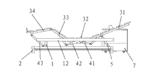
Fig. 1 is an electric up-down bed structural representation of the present utility model.
Fig. 2 is the structural representation of the electric up-down bed other direction of Fig. 1
Structural representation when Fig. 3 is an electric up-down bed rise state of the present utility model.
Fig. 4 is the structural representation of bed frame of the present utility model and following bedstead.
Fig. 5 is the structural representation after Fig. 1 removes bed board, night-table.
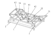
Fig. 6 is the structural representation during electric up-down bed rise state among Fig. 5.
Description of reference numerals:
1---bed frame 11---pulley
The following bedstead of 12---bed board support bars 2---
21---chute 22---slide bar
23---pedal 3---gripper shoe
31---back gripper shoe 32---buttocks gripper shoe
33---huckle gripper shoe 34---calf gripper shoe
35---bed board 4---lowering or hoisting gear
41---back pusher motor 42---shank pusher motor
43---shank jury strut 5---back strut
6---control box 7---night-table.
The specific embodiment
Below in conjunction with the drawings and specific embodiments the utility model being described in further detail, is not that practical range of the present utility model is limited to this.
Extremely shown in Figure 6 as Fig. 1, present embodiment a kind of electric up-down bed, it comprises bed frame 1, following bedstead 2, gripper shoe 3, lowering or hoisting gear 4, back strut 5, gripper shoe 3 comprises the bed board 25 of upside, the reinforcement strut of bed board 25 downsides, leave the gap between each bed board 25, interfere mutually when avoiding bed board 25 liftings.Gripper shoe 3 is divided into back gripper shoe 31, buttocks gripper shoe 32 according to the position difference of body support.One end of back gripper shoe 31 and an end of buttocks gripper shoe 32 are hinged, buttocks gripper shoe 32 is fixedlyed connected with bed frame 1, lowering or hoisting gear 4 comprises back pusher motor 41, back pusher motor 41 is hinged with bed frame 1, the push rod of back pusher motor 41 and back gripper shoe 31 are hinged, following bedstead 2 is slidingly connected with bed frame 1, and an end of back strut 5 and following bedstead 2 are hinged, and the other end of back strut 5 and back gripper shoe 31 are hinged.During use, an end of back gripper shoe 31 is freely, and under the driving of back pusher motor 41, certain angle is risen in rotation thereby back gripper shoe 31 makes progress around the hinged place of back gripper shoe 31 and buttocks gripper shoe 32.Simultaneously, back strut 5 rotates certain angle around the hinged place of back strut 5 and back gripper shoe 31, thereby make that the power of 5 pairs of back gripper shoes 31 of back strut is increasing at the component of vertical direction, make the 31 easier rises of back gripper shoe, reduced the load of back pusher motor 41, helped reducing cost.And when the push rod of back pusher motor 41 extended, because the effect of back strut 5, bed frame 1 was along bedstead 2 is to the slip of head of a bed direction down, and in the present embodiment, the head of a bed is meant a side of close back gripper shoe 31.Fig. 3, Figure 6 shows that electric up-down bed when rising.
As shown in Figure 6, back strut 5 is two, is symmetricly set in the both sides of bed frame 1.
As shown in Figure 4, bed frame 1 is provided with four pulleys 11, and following bedstead 2 is provided with four chutes 21, and bed frame 1 is slidingly connected by pulley 11 and following bedstead 2.
Further, shank also can rise when the people is lied on a bed, the gripper shoe 3 of present embodiment also comprises huckle gripper shoe 33, calf gripper shoe 34, lowering or hoisting gear 4 also comprises shank pusher motor 42, shank jury strut 43, one end of the other end of buttocks gripper shoe 32 and huckle gripper shoe 33 is hinged, one end of the other end of huckle gripper shoe 33 and calf gripper shoe 34 is hinged, one end of the other end of shank gripper shoe 34 and shank jury strut 43 is hinged, the other end of shank jury strut 43 and bed frame 1 are hinged, shank pusher motor 42 is hinged with bed frame 1, and the push rod and the huckle gripper shoe 33 of shank strut motor 42 are hinged.
Need to prove that back pusher motor 41, shank pusher motor 42 both can drive respectively, also can drive simultaneously, thereby control back gripper shoe 31 respectively or simultaneously, thigh gripper shoe 33, shank gripper shoe 34.The utility model scientific structure is simple, and the intensity height is reliable and stable, easy to use.
Further, bed frame 1 is provided with bed board support bar 12, when back gripper shoe 32, huckle gripper shoe 33 and calf gripper shoe 34 fell, the bed board 35 of back gripper shoe 32, huckle gripper shoe 33 and calf gripper shoe 34 was conflicted respectively and is connected the upper surface of bed board support bar 12.
As shown in Figure 2, further be provided with control box 6, control box 6 is electrically connected with back pusher motor 41, shank pusher motor 42 respectively, also can be provided with remote control panel, and is by remote control panel controlled in wireless control box 6, easy to use.
For easy to use, the utility model also comprises night-table 7, and the bottom of night-table 7 is provided with universal wheel, can move with bed.Further, following bedstead 2 sides are provided with slide bar 22, and night-table 7 is slidingly connected with slide bar 22, thereby can be so that night-table 7 moves along slide bar 22.
As shown in Figure 1, following bedstead 2 both sides are provided with pedal 23, and this pedal can be used for the people in bed the time, above pin is placed on, also can be used to put footwear or other article.Can also be provided with baffle plate on bed board 35, when placing mattress on this is electric up-down bed, baffle plate can carry out spacing to mattress.
For present embodiment, adopt the bolt assembling between each part or the assembly, can process each part or assembly earlier like this, the volume of packing is little, assembles when to be used again, is convenient to transportation.
Should be noted that at last; above embodiment is only in order to the explanation the technical solution of the utility model; but not to the restriction of the utility model protection domain; although the utility model has been done to explain with reference to preferred embodiment; those of ordinary skill in the art is to be understood that; can make amendment or be equal to replacement the technical solution of the utility model, and not break away from the essence and the scope of technical solutions of the utility model.
Claims (10)
- One kind electric up-down bed, it is characterized in that: comprise bed frame (1), following bedstead (2), gripper shoe (3), lowering or hoisting gear (4), back strut (5), gripper shoe (3) comprises back gripper shoe (31), buttocks gripper shoe (32), one end of one end of back gripper shoe (31) and buttocks gripper shoe (32) is hinged, buttocks gripper shoe (32) is fixedlyed connected with bed frame (1), lowering or hoisting gear (4) comprises back pusher motor (41), back pusher motor (41) is hinged with bed frame (1), the push rod of back pusher motor (41) and back gripper shoe (31) are hinged, following bedstead (2) is slidingly connected with bed frame (1), one end of back strut (5) is hinged with following bedstead (2), the other end of back strut (5) and back gripper shoe (31) are hinged, when the push rod of back pusher motor (41) extends, back gripper shoe (31) is upwards rotated around the back gripper shoe (31) and the hinged place of buttocks gripper shoe (32), back strut (5) rotates around the hinged place of back strut (5) with back gripper shoe (31), slides to head of a bed direction in bed frame (1) edge bedstead (2) down.
- 2. according to claim 1 a kind of electric up-down bed, it is characterized in that: back strut (5) is two, is symmetricly set in the both sides of bed frame (1).
- 3. according to claim 1 a kind of electric up-down bed, it is characterized in that: bed frame (1) is provided with four pulleys (11), following bedstead (2) is provided with four chutes (21), and bed frame (1) is slidingly connected by pulley (11) and following bedstead (2).
- According to claim 1 to 3 any one described a kind of electric up-down bed, it is characterized in that: gripper shoe (3) also comprises huckle gripper shoe (33), calf gripper shoe (34), lowering or hoisting gear (4) also comprises shank pusher motor (42), shank jury strut (43), one end of the other end of buttocks gripper shoe (32) and huckle gripper shoe (33) is hinged, one end of the other end of huckle gripper shoe (33) and calf gripper shoe (34) is hinged, one end of the other end of shank gripper shoe (34) and shank jury strut (43) is hinged, the other end of shank jury strut (43) and bed frame (1) are hinged, shank pusher motor (42) is hinged with bed frame (1), and the push rod of shank strut motor (42) and huckle gripper shoe (33) are hinged.
- 5. according to claim 4 a kind of electric up-down bed, it is characterized in that: the upside of back gripper shoe (31), buttocks gripper shoe (32), huckle gripper shoe (33) and calf gripper shoe (34) is respectively arranged with several bed boards (35), and each bed board leaves the gap between (35).
- 6. according to claim 5 a kind of electric up-down bed, it is characterized in that: bed frame (1) is provided with bed board support bar (12), when back gripper shoe (32), huckle gripper shoe (33) and calf gripper shoe (34) when falling, the bed board (35) of back gripper shoe (32), huckle gripper shoe (33) and calf gripper shoe (34) is conflicted respectively and is connected the upper surface of bed board support bar (12).
- 7. according to claim 4 a kind of electric up-down bed, it is characterized in that: further be provided with control box (6), control box (6) is electrically connected with back pusher motor (41), shank pusher motor (42) respectively.
- 8. according to claim 1 a kind of electric up-down bed, it is characterized in that: also comprise night-table (7), the bottom of night-table (7) is provided with universal wheel.
- 9. according to claim 8 a kind of electric up-down bed, it is characterized in that: following bedstead (2) side is provided with slide bar (22), and night-table (7) is slidingly connected with slide bar (22).
- 10. according to claim 1 a kind of electric up-down bed, it is characterized in that: following bedstead (2) both sides are provided with pedal (23).
Priority Applications (1)
| Application Number | Priority Date | Filing Date | Title |
|---|---|---|---|
| CN 201220743150 CN203073843U (en) | 2012-12-31 | 2012-12-31 | Power-driven lifting bed |
Applications Claiming Priority (1)
| Application Number | Priority Date | Filing Date | Title |
|---|---|---|---|
| CN 201220743150 CN203073843U (en) | 2012-12-31 | 2012-12-31 | Power-driven lifting bed |
Publications (1)
| Publication Number | Publication Date |
|---|---|
| CN203073843U true CN203073843U (en) | 2013-07-24 |
Family
ID=48819740
Family Applications (1)
| Application Number | Title | Priority Date | Filing Date |
|---|---|---|---|
| CN 201220743150 Expired - Fee Related CN203073843U (en) | 2012-12-31 | 2012-12-31 | Power-driven lifting bed |
Country Status (1)
| Country | Link |
|---|---|
| CN (1) | CN203073843U (en) |
Cited By (5)
| Publication number | Priority date | Publication date | Assignee | Title |
|---|---|---|---|---|
| CN105534138A (en) * | 2016-02-04 | 2016-05-04 | 嘉兴佰世电动床有限公司 | Intelligent remote control electric bed |
| CN105534139A (en) * | 2016-02-04 | 2016-05-04 | 嘉兴佰世电动床有限公司 | Back hoisting frame of electric bed |
| CN105942752A (en) * | 2016-06-23 | 2016-09-21 | 惠州金桔家具有限公司 | Electric bed |
| CN105996561A (en) * | 2016-08-05 | 2016-10-12 | 惠州金桔家具有限公司 | Bed with storage function |
| CN107928236A (en) * | 2017-12-08 | 2018-04-20 | 李�杰 | A kind of home-use bed of novel intelligent |
-
2012
- 2012-12-31 CN CN 201220743150 patent/CN203073843U/en not_active Expired - Fee Related
Cited By (5)
| Publication number | Priority date | Publication date | Assignee | Title |
|---|---|---|---|---|
| CN105534138A (en) * | 2016-02-04 | 2016-05-04 | 嘉兴佰世电动床有限公司 | Intelligent remote control electric bed |
| CN105534139A (en) * | 2016-02-04 | 2016-05-04 | 嘉兴佰世电动床有限公司 | Back hoisting frame of electric bed |
| CN105942752A (en) * | 2016-06-23 | 2016-09-21 | 惠州金桔家具有限公司 | Electric bed |
| CN105996561A (en) * | 2016-08-05 | 2016-10-12 | 惠州金桔家具有限公司 | Bed with storage function |
| CN107928236A (en) * | 2017-12-08 | 2018-04-20 | 李�杰 | A kind of home-use bed of novel intelligent |
Similar Documents
| Publication | Publication Date | Title |
|---|---|---|
| CN203073843U (en) | Power-driven lifting bed | |
| CN204352073U (en) | A kind of paralytic's nursing bed of convenient movement | |
| CN106580587A (en) | Automatic-separating-and-docking integrated robot | |
| CN205338226U (en) | Multifunctional bedside table | |
| CN207837783U (en) | Multifunctional assembled care bed | |
| CN205903370U (en) | Multifunctional medical treatment bed | |
| CN103142059A (en) | Ultralow household multifunctional electric bed | |
| CN201299724Y (en) | Multifunction nursing bed | |
| CN201727170U (en) | Bed capable of integrally lifting | |
| CN202999833U (en) | Computer desk | |
| CN203538846U (en) | Electric sleeping posture adjusting bed | |
| CN203262741U (en) | Household multifunctional electric bed | |
| CN203898594U (en) | Multifunctional domestic nursing bed for lower leg bending | |
| CN204636784U (en) | A kind of lift bedstead | |
| CN203073844U (en) | Electric lifting bed | |
| CN203244511U (en) | Transferring bed | |
| CN204764490U (en) | Motion bed bedstead | |
| CN203693947U (en) | Multifunctional automatic control nursing bed | |
| CN204446386U (en) | A kind of multifunctional overturn bed | |
| CN203244524U (en) | Multifunctional power-driven body turnover bed | |
| CN203735245U (en) | Lift type pet nursing platform convenient to fix and position | |
| CN208259863U (en) | A kind of young people's multifunctional medicinal bed | |
| CN112545775A (en) | Intelligent transfer bed | |
| CN201260534Y (en) | Health bed for reversely sleeping | |
| CN103393511A (en) | Bed for pregnant women |
Legal Events
| Date | Code | Title | Description |
|---|---|---|---|
| C14 | Grant of patent or utility model | ||
| GR01 | Patent grant | ||
| TR01 | Transfer of patent right | ||
| TR01 | Transfer of patent right |
Effective date of registration: 20180116 Address after: Wang Cao Lu Cun Niu Dun step 523219 in Guangdong city of Dongguan Province Patentee after: DONGGUAN YAXUAN HARDWARE Co.,Ltd. Address before: 523000 Guangdong city of Dongguan Province Wang Cao Niu Industrial Zone under the Patentee before: Li Zhong |
|
| CF01 | Termination of patent right due to non-payment of annual fee | ||
| CF01 | Termination of patent right due to non-payment of annual fee |
Granted publication date: 20130724 Termination date: 20211231 |