CN203072157U - Automatic test device for earphone wire control key function - Google Patents
Automatic test device for earphone wire control key function Download PDFInfo
- Publication number
- CN203072157U CN203072157U CN201320077693.5U CN201320077693U CN203072157U CN 203072157 U CN203072157 U CN 203072157U CN 201320077693 U CN201320077693 U CN 201320077693U CN 203072157 U CN203072157 U CN 203072157U
- Authority
- CN
- China
- Prior art keywords
- cylinder
- earphone
- traffic control
- line traffic
- pressure head
- Prior art date
- Legal status (The legal status is an assumption and is not a legal conclusion. Google has not performed a legal analysis and makes no representation as to the accuracy of the status listed.)
- Expired - Lifetime
Links
Images


Classifications
-
- Y—GENERAL TAGGING OF NEW TECHNOLOGICAL DEVELOPMENTS; GENERAL TAGGING OF CROSS-SECTIONAL TECHNOLOGIES SPANNING OVER SEVERAL SECTIONS OF THE IPC; TECHNICAL SUBJECTS COVERED BY FORMER USPC CROSS-REFERENCE ART COLLECTIONS [XRACs] AND DIGESTS
- Y02—TECHNOLOGIES OR APPLICATIONS FOR MITIGATION OR ADAPTATION AGAINST CLIMATE CHANGE
- Y02P—CLIMATE CHANGE MITIGATION TECHNOLOGIES IN THE PRODUCTION OR PROCESSING OF GOODS
- Y02P90/00—Enabling technologies with a potential contribution to greenhouse gas [GHG] emissions mitigation
- Y02P90/02—Total factory control, e.g. smart factories, flexible manufacturing systems [FMS] or integrated manufacturing systems [IMS]
Landscapes
- Testing Of Devices, Machine Parts, Or Other Structures Thereof (AREA)
Abstract
本实用新型公开了一种耳机线控按键功能自动测试装置,属于电子产品测试装置技术领域,包括由第一驱动装置驱动的下压模块、产品放置块和由第二驱动装置驱动的顶柱,所述下压模块与所述产品放置块位置相对应,所述产品放置块上设有与线控组件上的触点相对应的通孔,所述顶柱与所述通孔一一对应;并且还包括接口电路板,所述接口电路板连接测试单元,所述第一驱动装置和第二驱动装置均与所述测试单元电连接。本实用新型通过测试单元发出信号,利用下压模块压紧耳机,通过顶柱依次动作来完成线控组件上触点的按下、松开并采集耳机返回信息,实现自动测试按键功能,不仅测试速度快,效率高,而且避免了由人工操作带来的误测率高和按键破损等问题。
The utility model discloses an automatic test device for the function of an earphone wire-controlled button, which belongs to the technical field of electronic product test devices and comprises a pressing module driven by a first drive device, a product placement block and a top column driven by a second drive device. The press-down module corresponds to the position of the product placement block, and the product placement block is provided with through holes corresponding to the contacts on the wire control assembly, and the push posts correspond to the through holes one by one; Furthermore, an interface circuit board is also included, the interface circuit board is connected to the test unit, and both the first drive device and the second drive device are electrically connected to the test unit. The utility model sends a signal through the test unit, uses the pressing module to press the earphone, and completes the pressing and releasing of the contacts on the wire control component through the sequential actions of the top column and collects the return information of the earphone, so as to realize the automatic test key function, not only testing The speed is fast, the efficiency is high, and problems such as high false detection rate and key damage caused by manual operation are avoided.
Description
技术领域technical field
本实用新型属于电子产品测试装置技术领域,尤其涉及一种耳机线控按键功能自动测试装置。The utility model belongs to the technical field of testing devices for electronic products, in particular to an automatic testing device for the function of an earphone wire control button.
背景技术Background technique
近年来,随着人们消费观念的不断升级,许多消费者希望更多的用耳机线控来操作手机或播放器,因此对线控耳机的设计、生产提出了更高要求。In recent years, with the continuous upgrading of people's consumption concept, many consumers hope to use more earphone wire control to operate mobile phones or players, so higher requirements are put forward for the design and production of wire earphones.
目前线控耳机的生产、测试正朝着自动化、智能化的方向发展,但耳机线控按键的测试一直都采用手动方式,不仅测试速度慢,效率低下,而且容易引起操作员劳累,造成测试的遗漏,误测率高,并且因手动按键力度不均,易造成按键的破损。At present, the production and testing of wire-controlled earphones are developing in the direction of automation and intelligence, but the testing of the wire-controlled buttons of the earphones has always been done manually. Omission, the false detection rate is high, and because of the uneven force of the manual key, it is easy to cause damage to the key.
实用新型内容Utility model content
本实用新型所要解决的技术问题是:提供一种耳机线控按键功能自动测试装置,以解决线控耳机测试按键功能时因使用人工手动测试而带来的效率低下,误测率高的技术问题。The technical problem to be solved by the utility model is to provide an automatic test device for the function of the earphone wire-controlled button to solve the technical problems of low efficiency and high false detection rate caused by manual testing when the wire-controlled earphone is tested for the button function .
为解决上述技术问题,本实用新型的技术方案是:耳机线控按键功能自动测试装置,包括底盒和固定连接在所述底盒上的测试平台,所述测试平台上滑动安装有由第一驱动装置驱动的用于压住所述耳机的下压模块,与所述下压模块位置相对的所述测试平台上设有产品放置块,所述产品放置块上设有容纳耳机线控组件的产品放置区,所述产品放置区内的所述产品放置块上设有与线控组件上的触点相对应的通孔,所述底盒和测试平台形成的空腔内设有由第二驱动装置驱动的顶柱,所述顶柱滑动安装于所述测试平台上,所述顶柱与所述通孔一一对应;所述空腔内设有用于连接耳机插头的接口电路板,所述接口电路板连接测试单元,所述第一驱动装置和第二驱动装置均与所述测试单元电连接。In order to solve the above-mentioned technical problems, the technical solution of the utility model is: an automatic test device for the function of the earphone wire control button, including a bottom box and a test platform fixedly connected to the bottom box, on which a first The push-down module driven by the driving device is used to press down the earphone, and the test platform opposite to the press-down module is provided with a product placement block, and the product placement block is provided with a seat for accommodating the earphone wire control assembly. In the product placement area, the product placement block in the product placement area is provided with through holes corresponding to the contacts on the wire control assembly, and the cavity formed by the bottom box and the test platform is provided with a second The jack driven by the driving device, the jack is slidably installed on the test platform, and the jack is in one-to-one correspondence with the through holes; the cavity is provided with an interface circuit board for connecting the earphone plug, so The interface circuit board is connected to the test unit, and both the first drive device and the second drive device are electrically connected to the test unit.
作为一种改进,所述下压模块包括与所述第一驱动装置相连的压头上板和固定安装于所述压头上板上的压头下板,所述压头下板上滑动安装有若干个用于压住线控组件的压柱,所述压柱与所述压头上板之间设有压缩弹簧。As an improvement, the pressing module includes an upper plate of the indenter connected to the first driving device and a lower plate of the indenter fixedly mounted on the upper plate of the indenter, and the lower plate of the indenter is slidably installed There are several pressure columns for pressing down the wire control assembly, and a compression spring is arranged between the pressure columns and the upper plate of the pressure head.
作为进一步的改进,所述第一驱动装置包括由第一电磁阀驱动的第一气缸,所述第一气缸的缸体固定安装于支架上,所述支架固定安装于所述测试平台上,所述第一气缸的活塞杆连接所述压头上板。As a further improvement, the first driving device includes a first cylinder driven by a first solenoid valve, the cylinder body of the first cylinder is fixedly installed on a bracket, and the bracket is fixedly installed on the test platform, so The piston rod of the first cylinder is connected to the upper plate of the pressure head.
作为进一步的改进,所述压头上板与支架之间设有导向柱。As a further improvement, a guide column is provided between the upper plate of the indenter and the bracket.
作为进一步的改进,所述下压模块还包括用于检测所述压头下板位置的传感器,所述传感器与所述测试单元电连接。As a further improvement, the pressing module further includes a sensor for detecting the position of the lower plate of the pressing head, and the sensor is electrically connected to the testing unit.
作为进一步的改进,所述第二驱动装置包括由第二电磁阀驱动的第二气缸,所述第二气缸的缸体固定安装于所述测试平台上,所述第二气缸的活塞杆连接所述顶柱。As a further improvement, the second driving device includes a second cylinder driven by a second solenoid valve, the cylinder body of the second cylinder is fixedly installed on the test platform, and the piston rod of the second cylinder is connected to the Describe the top pillar.
作为进一步的改进,所述第一气缸和第二气缸的进气管路上均设有气压调节阀。As a further improvement, air pressure regulating valves are provided on the intake lines of the first cylinder and the second cylinder.
作为进一步的改进,所述测试单元包括单片机、电源转换模块和输入、输出接口。As a further improvement, the test unit includes a single chip microcomputer, a power conversion module and input and output interfaces.
采用了上述技术方案后,本实用新型的有益效果是:耳机线控按键功能自动测试装置,由于设计了由第一驱动装置驱动的下压模块、产品放置块和由第二驱动装置驱动的顶柱,所述下压模块与所述产品放置块位置相对应,所述产品放置块上设有与线控组件上的触点相对应的通孔,所述顶柱与所述通孔一一对应;并且设计了用于连接耳机插头的接口电路板,所述接口电路板连接测试单元,所述第一驱动装置和第二驱动装置均与所述测试单元电连接,因而通过测试单元发出信号,利用下压模块压紧耳机,通过顶柱依次动作来完成线控组件上触点的按下、松开并采集耳机返回信息,实现自动测试按键功能,不仅测试速度快,效率高,而且避免了由人工操作带来的误测率高和按键破损等问题。After adopting the above-mentioned technical scheme, the beneficial effect of the utility model is: the automatic test device for the function of the earphone wire control button, due to the design of the pressing module driven by the first driving device, the product placement block and the top driven by the second driving device column, the press-down module corresponds to the position of the product placement block, and the product placement block is provided with a through hole corresponding to the contact on the wire control assembly, and the top column and the through hole are one by one Corresponding; and an interface circuit board for connecting the earphone plug is designed, the interface circuit board is connected to the test unit, and the first driving device and the second driving device are both electrically connected to the test unit, thus sending a signal through the test unit , use the pressing module to press the earphones, press and release the contacts on the wire control component and collect the return information of the earphones through the action of the top column in sequence, and realize the automatic test button function, which not only has fast test speed and high efficiency, but also avoids Problems such as high false detection rate and key damage caused by manual operation are solved.
由于所述下压模块上设计了压柱和压缩弹簧,因而当下压模块接触耳机时,压柱使两者之间的接触由面接触变为点接触,有利于均匀地压紧耳机;并且压缩弹簧限制了压柱的下压力度,防止压力过大对耳机造成损伤。Since the pressure column and the compression spring are designed on the pressure-down module, when the pressure-down module contacts the earphone, the pressure column makes the contact between the two change from surface contact to point contact, which is beneficial to evenly compress the earphone; and compress The spring limits the downward pressure of the pressure column to prevent damage to the earphone caused by excessive pressure.
由于所述第一驱动装置包括由第一电磁阀驱动的第一气缸,所述第一气缸的活塞杆连接所述压头上板,因而第一气缸带动下压模块下压或抬起,实现耳机的压紧或松开。Since the first driving device includes a first cylinder driven by a first solenoid valve, the piston rod of the first cylinder is connected to the upper plate of the pressure head, so the first cylinder drives the pressing module to press down or lift up, realizing Compression or loosening of earphones.
由于所述压头上板与支架之间设有导向柱,因而导向柱对压头上板起导向作用,使压头上板在下压或抬起时保持水平,同时保证水平的压住耳机。Since the guide column is arranged between the upper plate of the indenter and the support, the guide column acts as a guide to the upper plate of the indenter, so that the upper plate of the indenter remains horizontal when pressed down or lifted, and simultaneously ensures that the earphone is pressed horizontally.
由于所述下压模块还包括传感器,所述传感器与所述测试单元电连接,因而传感器可用于检测压头下板是否已经下压或抬起,并输出相应信号给测试单元,作为开始或结束的信号。Since the pressing module also includes a sensor, which is electrically connected to the test unit, the sensor can be used to detect whether the lower plate of the indenter has been pressed or lifted, and output a corresponding signal to the test unit as a start or end signal of.
由于所述第二驱动装置包括由第二电磁阀驱动的第二气缸,所述第二气缸的活塞杆连接所述顶柱,因而在第二气缸的驱动下,顶柱的上顶力大小恒定,线控组件上的触点受力均匀,不受人工操作施力不均的影响,测试结果准确。Since the second driving device includes a second air cylinder driven by a second solenoid valve, the piston rod of the second air cylinder is connected to the ejector column, and thus the upper force of the ejector column is constant under the drive of the second air cylinder , The contacts on the wire control component are evenly stressed, not affected by uneven force applied by manual operation, and the test results are accurate.
由于所述第一气缸和第二气缸的进气管路上均设有气压调节阀,因而可根据实际情况通过气压调节阀控制第一气缸的下压力和第二气缸的上顶力,以便合理控制下压力和上顶力的大小。Since the air pressure regulating valves are installed on the air intake pipelines of the first cylinder and the second cylinder, the downforce of the first cylinder and the upper jacking force of the second cylinder can be controlled through the air pressure regulating valve according to the actual situation, so as to reasonably control the downforce. The magnitude of pressure and jacking force.
由于所述测试单元包括单片机、电源转换模块和输入、输出接口,因而测试单元作为主要的逻辑控制部分,采用单片机编程,负责第一气缸和第二气缸的有序动作和数据的采集分析并输出测试结果。Since the test unit includes a single-chip microcomputer, a power conversion module, and input and output interfaces, the test unit, as the main logic control part, adopts single-chip microcomputer programming, and is responsible for the orderly actions of the first cylinder and the second cylinder and the collection, analysis and output of data. Test Results.
附图说明Description of drawings
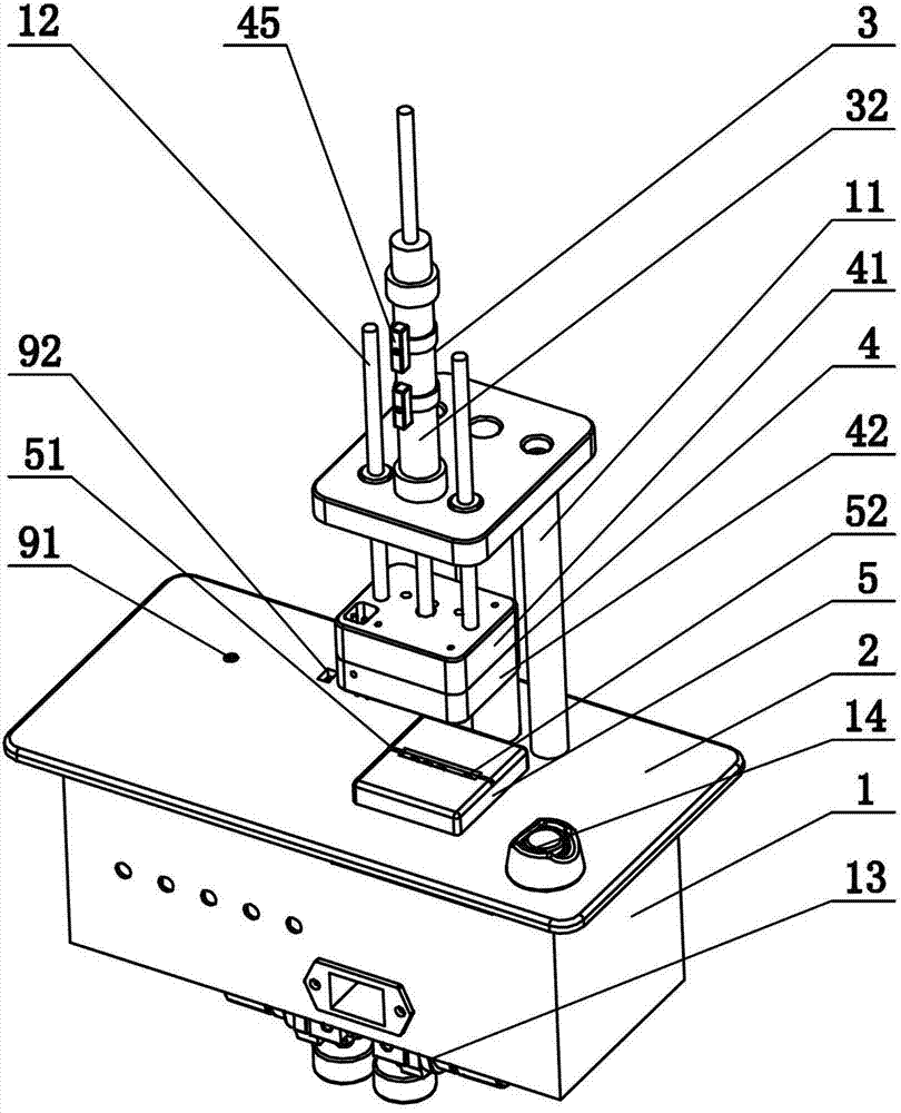
图1是本实用新型提供的结构示意图;Fig. 1 is the structural representation provided by the utility model;
图2是图1的纵截面结构示意图;Fig. 2 is a schematic view of the longitudinal section of Fig. 1;
图3是下压模块及第一驱动装置的分解结构示意图;Fig. 3 is a schematic diagram of an exploded structure of a pressing module and a first driving device;
图4是空腔内部的分解结构示意图;Fig. 4 is a schematic diagram of an exploded structure inside the cavity;
图中:1、底盒,2、测试平台,3、第一驱动装置,31、第一电磁阀,32、第一气缸,4、下压模块,41、压头上板,42、压头下板,43、压柱,44、压缩弹簧,45、传感器,5、产品放置块,51、产品放置区,52、通孔,6、空腔,7、第二驱动装置,71、第二电磁阀,72、第二气缸,8、顶柱,9、接口电路板,91、输入接口,92、输出接口,10、测试单元,11、支架,12、导向柱,13、气压调节阀,14、开关。In the figure: 1. Bottom box, 2. Test platform, 3. The first driving device, 31. The first solenoid valve, 32. The first cylinder, 4. The pressing module, 41. The upper plate of the pressure head, 42. The pressure head Lower plate, 43, pressure column, 44, compression spring, 45, sensor, 5, product placement block, 51, product placement area, 52, through hole, 6, cavity, 7, second driving device, 71, second Solenoid valve, 72, second cylinder, 8, top column, 9, interface circuit board, 91, input interface, 92, output interface, 10, test unit, 11, bracket, 12, guide column, 13, air pressure regulating valve, 14. Switch.
具体实施方式Detailed ways
为了使本实用新型的目的、技术方案及优点更加清楚明白,以下结合附图及实施例,对本实用新型进行进一步详细说明。应当理解,此处所描述的具体实施例仅仅用以解释本实用新型,并不用于限定本实用新型。In order to make the purpose, technical solution and advantages of the utility model clearer, the utility model will be further described in detail below in conjunction with the accompanying drawings and embodiments. It should be understood that the specific embodiments described here are only used to explain the utility model, and are not intended to limit the utility model.
如图1和图2共同所示,耳机线控按键功能自动测试装置,包括底盒1和固定连接在底盒1上的测试平台2,测试平台2上滑动安装有由第一驱动装置3驱动的用于压住耳机的下压模块4,与下压模块4位置相对的测试平台2上设有产品放置块5,产品放置块5上设有容纳耳机线控组件的产品放置区51,产品放置区51内的产品放置块5上设有与线控组件上的触点相对应的通孔52,通孔52的位置和通孔52的大小由线控组件上触点的位置和尺寸决定,底盒1和测试平台2形成的空腔6内设有由第二驱动装置7驱动的顶柱8,顶柱8滑动安装于测试平台2上,顶柱8与通孔52一一对应;空腔6内设有用于连接耳机插头的接口电路板9,接口电路板9包括用于连接耳机插头的输入接口91和用于输出信号的输出接口92,输入接口91可为3.5mm音频插座,输出接口92可为RS232,接口电路板9连接测试单元10,第一驱动装置3和第二驱动装置7均与测试单元10电连接,测试单元10包括单片机、电源转换模块和输入、输出接口,测试单元10作为主要的逻辑控制部分,采用单片机编程,负责第一驱动装置3和第二驱动装置7的有序动作和数据的采集分析并输出测试结果。通过测试单元10发出信号,利用下压模块4压紧耳机,通过顶柱8依次动作来完成线控组件上触点的按下、松开并采集耳机返回信息,实现自动测试按键功能,不仅测试速度快,效率高,而且避免了由人工操作带来的误测率高和按键破损等问题。As shown in Figure 1 and Figure 2 together, the automatic test device for the function of the earphone wire control button includes a
如图2和图3共同所示,下压模块4包括与第一驱动装置3相连的压头上板41和固定安装于压头上板41上的压头下板42,压头下板42上滑动安装有若干个用于压住线控组件的压柱43,压柱43与压头上板41之间设有压缩弹簧44,压柱43的位置由耳机尺寸决定,当下压模块4接触耳机时,压柱43使两者之间的接触由面接触变为点接触,有利于均匀地压紧耳机;并且压缩弹簧44限制了压柱43的下压力度,防止压力过大对耳机造成损伤。下压模块4还包括用于检测压头下板42位置的传感器45,传感器45与测试单元10电连接,传感器45可用于检测压头下板42是否已经下压或抬起,并输出相应信号给测试单元10,作为开始或结束的信号。As shown in Fig. 2 and Fig. 3 together, the pressing down
如图2、图3和图4共同所示,第一驱动装置3包括由第一电磁阀31驱动的第一气缸32,第一气缸32的缸体固定安装于支架11上,支架11固定安装于测试平台2上,第一气缸32的活塞杆连接压头上板41,第一气缸32带动下压模块4下压或抬起,实现耳机的压紧或松开,当然,第一驱动装置3也可以为第一电磁阀31驱动的液压缸等,本领域技术人员可根据实际情况来设定,在此不再赘述;压头上板41与支架11之间设有导向柱12,导向柱12设计两根且离第一气缸32的距离相等,导向柱12对压头上板41起导向作用,使压头上板41在下压或抬起时保持水平,同时保证水平的压住耳机;第二驱动装置7包括由第二电磁阀71驱动的第二气缸72,第二气缸72的缸体固定安装于测试平台2上,第二气缸72的活塞杆连接顶柱8,在第二气缸72的驱动下,顶柱8的上顶力大小恒定,线控组件上的触点受力均匀,不受人工操作施力不均的影响,测试结果准确,当然,第二驱动装置7也可以为第二电磁阀71驱动的液压缸等,本领域技术人员可根据实际情况来设定,在此不再赘述;第一气缸32和第二气缸72的进气管路上均设有气压调节阀13,可根据实际情况通过气压调节阀13控制第一气缸32的下压力和第二气缸72的上顶力,以便合理控制下压力和上顶力的大小,可手动调节气压调节阀13。As shown in Fig. 2, Fig. 3 and Fig. 4 together, the
为了便于理解,下述给出了本实用新型提供的耳机线控按键功能自动测试装置的工作过程:For ease of understanding, the working process of the automatic test device for the function of the earphone wire control button provided by the utility model is given below:
将耳机线控组件放置在产品放置块5上的产品放置区51内,线控组件上的触点一一对应通孔52;将耳机的插头插入位于接口电路板9的输入接口91上;按下开关14开始测试;测试单元10发出信号至第一电磁阀31,然后第一电磁阀31驱动第一气缸32带动下压模块4压紧耳机,传感器45输出信号至测试单元10;根据编程要求的触点测试顺序,测试单元10发出信号至第二电磁阀71,然后第二电磁阀71驱动第二气缸72带动顶柱8按下触点,同时开始采集来自接口电路板9的信号信息;将该信息与程序要求的判断标准进行比对,如果合格就输出合格信息,否则输出不良,测试单元10发出信号至第二电磁阀71,然后第二电磁阀71驱动第二气缸72带动顶柱8松开触点;然后再进行其他触点的测试,直到所有线控组件上触点都测试完毕后发送信号让下压模块4抬起,完成一只产品的测试。Place the earphone wire control assembly in the
本实用新型提供的耳机线控按键功能自动测试装置,由于设计了由第一驱动装置3驱动的下压模块4、产品放置块5和由第二驱动装置7驱动的顶柱8,下压模块4与产品放置块5位置相对应,产品放置块5上设有与线控组件上的触点相对应的通孔52,顶柱8与通孔52一一对应;并且设计了用于连接耳机插头的接口电路板9,接口电路板9连接测试单元10,第一驱动装置3和第二驱动装置7均与测试单元10电连接,因而通过测试单元10发出信号,利用下压模块4压紧耳机,通过顶柱8依次动作来完成线控组件上触点的按下、松开并采集耳机返回信息,实现自动测试按键功能,不仅测试速度快,效率高,而且避免了由人工操作带来的误测率高和按键破损等问题。The automatic test device for the function of the earphone wire control button provided by the utility model, due to the design of the
以上所述仅为本实用新型的较佳实施例而已,并不用以限制本实用新型,凡在本实用新型的精神和原则之内所作的任何修改、等同替换和改进等,均应包含在本实用新型的保护范围之内。The above descriptions are only preferred embodiments of the present utility model, and are not intended to limit the present utility model. Any modifications, equivalent replacements and improvements made within the spirit and principles of the present utility model shall be included in this utility model. within the scope of protection of utility models.
Claims (8)
Priority Applications (1)
| Application Number | Priority Date | Filing Date | Title |
|---|---|---|---|
| CN201320077693.5U CN203072157U (en) | 2013-02-19 | 2013-02-19 | Automatic test device for earphone wire control key function |
Applications Claiming Priority (1)
| Application Number | Priority Date | Filing Date | Title |
|---|---|---|---|
| CN201320077693.5U CN203072157U (en) | 2013-02-19 | 2013-02-19 | Automatic test device for earphone wire control key function |
Publications (1)
| Publication Number | Publication Date |
|---|---|
| CN203072157U true CN203072157U (en) | 2013-07-17 |
Family
ID=48770898
Family Applications (1)
| Application Number | Title | Priority Date | Filing Date |
|---|---|---|---|
| CN201320077693.5U Expired - Lifetime CN203072157U (en) | 2013-02-19 | 2013-02-19 | Automatic test device for earphone wire control key function |
Country Status (1)
| Country | Link |
|---|---|
| CN (1) | CN203072157U (en) |
Cited By (5)
| Publication number | Priority date | Publication date | Assignee | Title |
|---|---|---|---|---|
| CN104181423A (en) * | 2014-08-26 | 2014-12-03 | 中国科学院电子学研究所 | Astronautic electronic device detection device |
| CN106768261A (en) * | 2016-12-20 | 2017-05-31 | 歌尔科技有限公司 | A kind of test device and method of intelligence wearing properties of product |
| CN107333465A (en) * | 2017-08-12 | 2017-11-07 | 珠海市运泰利自动化设备有限公司 | Earphone cord semi-finished product comprehensive function test machine |
| CN107831344A (en) * | 2017-12-19 | 2018-03-23 | 成都芯通软件有限公司 | One kind mixing board test device, test equipment and method of testing |
| CN112738677A (en) * | 2020-12-21 | 2021-04-30 | 歌尔光学科技有限公司 | Test houses and test equipment |
-
2013
- 2013-02-19 CN CN201320077693.5U patent/CN203072157U/en not_active Expired - Lifetime
Cited By (7)
| Publication number | Priority date | Publication date | Assignee | Title |
|---|---|---|---|---|
| CN104181423A (en) * | 2014-08-26 | 2014-12-03 | 中国科学院电子学研究所 | Astronautic electronic device detection device |
| CN104181423B (en) * | 2014-08-26 | 2017-01-11 | 中国科学院电子学研究所 | Astronautic electronic device detection device |
| CN106768261A (en) * | 2016-12-20 | 2017-05-31 | 歌尔科技有限公司 | A kind of test device and method of intelligence wearing properties of product |
| CN106768261B (en) * | 2016-12-20 | 2023-10-13 | 歌尔科技有限公司 | Device and method for testing performance of intelligent wearable product |
| CN107333465A (en) * | 2017-08-12 | 2017-11-07 | 珠海市运泰利自动化设备有限公司 | Earphone cord semi-finished product comprehensive function test machine |
| CN107831344A (en) * | 2017-12-19 | 2018-03-23 | 成都芯通软件有限公司 | One kind mixing board test device, test equipment and method of testing |
| CN112738677A (en) * | 2020-12-21 | 2021-04-30 | 歌尔光学科技有限公司 | Test houses and test equipment |
Similar Documents
| Publication | Publication Date | Title |
|---|---|---|
| CN202471762U (en) | Manual test base of chip | |
| CN205720564U (en) | A kind of PCBA board automatic testing device | |
| CN201689135U (en) | Controllable film button impedance test system of pressure | |
| CN108957178A (en) | More pressure adjustable test devices for bio-identification mould group | |
| CN202388203U (en) | Mobile phone shell processing device | |
| CN103096237A (en) | Multifunctional device used for assembling and testing driven-by-wire headset | |
| CN203072156U (en) | Automatic test system for earphone wire control key function | |
| CN108362998A (en) | A kind of touch chip presses compression testing device | |
| CN203934116U (en) | Flexible PCB manual test, burning jig | |
| CN208443573U (en) | A kind of Lock for automobile switch service life measurement tooling | |
| CN206311720U (en) | Fingerprint chip detecting system with manual depression mechanism | |
| CN202548165U (en) | Switching device for testing flexible circuit board circuit | |
| CN108362565A (en) | A kind of batch of touch chip presses compression testing device | |
| CN205484692U (en) | Socket with conducting resin anthropomorphic dummy finger test fingerprint chip | |
| CN206540977U (en) | Mobile phone motherboard and touch screen continuity test fixture | |
| CN203870215U (en) | Testing apparatus of control main board of liquid crystal display television set | |
| CN204302402U (en) | Capacitance plate sensor vacation pressure measurement jig | |
| CN201732148U (en) | Novel automatic keyboard plate testing device | |
| CN213210447U (en) | A detection tool for internal modules of a three-phase smart meter | |
| CN206459910U (en) | One kind is imparted knowledge to students with miniature Rock Mechanics Test device | |
| CN205620477U (en) | A adjustable automatic testing arrangement of highly reliable pressure for fingerprint module | |
| CN205080202U (en) | Test fixture | |
| CN210835154U (en) | VT testing device for COF product | |
| CN207396641U (en) | A kind of vacation compression testing device | |
| CN201699681U (en) | Touch button device of washing machine |
Legal Events
| Date | Code | Title | Description |
|---|---|---|---|
| C14 | Grant of patent or utility model | ||
| GR01 | Patent grant | ||
| C56 | Change in the name or address of the patentee | ||
| CP01 | Change in the name or title of a patent holder |
Address after: 261031 Dongfang Road, Weifang high tech Industrial Development Zone, Shandong, China, No. 268 Patentee after: GOERTEK Inc. Address before: 261031 Dongfang Road, Weifang high tech Industrial Development Zone, Shandong, China, No. 268 Patentee before: Goertek Inc. |
|
| CX01 | Expiry of patent term | ||
| CX01 | Expiry of patent term |
Granted publication date: 20130717 |