CN203061946U - Machine tool for slotting - Google Patents
Machine tool for slotting Download PDFInfo
- Publication number
- CN203061946U CN203061946U CN 201320094124 CN201320094124U CN203061946U CN 203061946 U CN203061946 U CN 203061946U CN 201320094124 CN201320094124 CN 201320094124 CN 201320094124 U CN201320094124 U CN 201320094124U CN 203061946 U CN203061946 U CN 203061946U
- Authority
- CN
- China
- Prior art keywords
- workpiece
- slotting
- machine tool
- lathe
- plate
- Prior art date
- Legal status (The legal status is an assumption and is not a legal conclusion. Google has not performed a legal analysis and makes no representation as to the accuracy of the status listed.)
- Expired - Fee Related
Links
Images


Abstract
The utility model discloses a machine tool for slotting. The machine tool comprises a bed body, a spindle box provided with a chuck, a polish rod, a lead screw, a sliding box, a planker and a tailstock provided with a sleeve, wherein a cutter used for processing workpieces is arranged between the spindle box and the tailstock, a work table is arranged on the planker, and a fixture is arranged on the work table; the fixture comprises a base plate, a baffle, a pressing plate and fasteners; and the baffle is arranged on the inner side face of the base plate, the workpiece is installed on the top face of the base plate, the pressing plate is arranged on the top face of the workpiece, and the fasteners fixed on the work table are arranged on the two ends of the pressing plate. The machine tool for the slotting, disclosed by the utility model, has a simple structure, and a common machine tool is reformed to the machine tool for the slotting. The cutter is changed necessarily according to grooves to be processed in the workpiece, identical procedures in processing of the workpiece are convenient to finish at one time, the product quality of the processed workpiece is guaranteed, and the workpiece processing time and cost are greatly reduced.
Description
Technical field
The utility model relates to a kind of machine tool structure renovation technique field, especially a kind of lathe for fluting.
Background technology
At present, part that has many identical cell bodies of existing machine tool processing is subjected to the influence of universal cutter, same processes need repeatedly machine, have problems such as many, quality defectiveness in processing parts man-hour simultaneously, very difficult primary feed machines, and effect is bad.
Summary of the invention
The utility model will solve the shortcoming of above-mentioned prior art, and a kind of lathe for fluting is provided, and transforms at existing machine tool, satisfies in the workpiece same processes primary feed and finishes.
The utility model solves the technical scheme that its technical problem adopts: this lathe for fluting, comprise lathe bed, have chuck main spindle box, polished rod, screw mandrel, slip crate, planker, have the tailstock of sleeve, wherein be provided with the cutter for processing work between main spindle box and the tailstock, its middle carriage is provided with workbench, and wherein workbench is provided with anchor clamps; Wherein anchor clamps comprise backing plate, baffle plate, pressing plate and securing member; Wherein the medial surface of backing plate is provided with baffle plate, and wherein the end face of backing plate is equipped with workpiece, and wherein the end face of workpiece is provided with pressing plate, and two of its center platen is provided with the securing member that is fixed on the workbench.Machine tool is transformed into for the lathe of slotting, saves cost, easy to use.
Wherein be provided with toply one in the chuck of main spindle box, wherein be provided with toply two in the sleeve of tailstock, between top one and top two, be provided with cutter.Cutter can be that integral type also can be separate assembling, but adopts split type gang tool, changes blade easily, saves cost.Make things convenient in the workpiece same processes primary feed to finish, guarantee the workpiece crudy.It is two top that the cutter fixed form adopts, and it is simple in structure.
Wherein backing plate is formed by stacking by one group of laminar plate.The convenient workpiece height of adjusting, operation easily.
Wherein baffle plate is provided with a pair ofly, is positioned at the two ends of backing plate one side, and the end face of baffle plate is provided with the cell body that passes through for cutter.Restriction workpiece motion s direction prevents the workpiece move left and right.
Its center platen is provided with a pair of, is positioned at the two ends of workpiece.It is more firm that workpiece is clamped, and prevents workpiece motion s.
When needing processing work, at first, by anchor clamps workpiece is fixed on the workbench, then, by top one and top two mounting cutters, then, start lathe and drive the cutter rotation, by planker control workpiece motion s direction, last, the groove of finishing on the workpiece processes at one time.
The effect that the utility model is useful is: the utility model is simple in structure, and machine tool is transformed into for the lathe of slotting.Cutter need change according to the groove that will process on the workpiece, makes things convenient in the workpiece same processes primary feed to finish, and guarantees the product quality of processing work, has significantly reduced time use amount and the cost of processing work.
Description of drawings
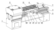
Fig. 1 is structural representation of the present utility model;
Fig. 2 is clamping workpiece figure of the present utility model;
Fig. 3 is A place enlarged drawing among Fig. 1.
Description of reference numerals: lathe bed 1, main spindle box 2, a top 2-1, polished rod 3, screw mandrel 4, slip crate 5, planker 6, tailstock 7, top two 7-1, workbench 8, anchor clamps 9, backing plate 9-1, baffle plate 9-2, pressing plate 9-3, securing member 9-4, workpiece 10, cutter 11, cell body 12.
The specific embodiment
The utility model is described in further detail below in conjunction with accompanying drawing:
With reference to accompanying drawing: this lathe for fluting, comprise lathe bed 1, have chuck main spindle box 2, polished rod 3, screw mandrel 4, slip crate 5, planker 6, have the tailstock 7 of sleeve, wherein be provided with the cutter 11 for processing work 10 between main spindle box 2 and the tailstock 7, its middle carriage 6 is provided with workbench 8, and wherein workbench 8 is provided with anchor clamps 9; Wherein anchor clamps 9 comprise backing plate 9-1, baffle plate 9-2, pressing plate 9-3 and securing member 9-4; Wherein the medial surface of backing plate 9-1 is provided with baffle plate 9-2, and wherein the end face of backing plate 9-1 is equipped with workpiece 10, and wherein the end face of workpiece 10 is provided with pressing plate 9-3, and two of its center platen 9-3 is provided with the securing member 9-4 that is fixed on the workbench 8.Wherein be provided with a top 2-1 in the chuck of main spindle box 2, wherein be provided with top two 7-1 in the sleeve of tailstock 7, between a top 2-1 and top two 7-1, be provided with cutter 11.Wherein backing plate 9-1 is formed by stacking by one group of laminar plate.Wherein baffle plate 9-2 is provided with a pair ofly, is positioned at the two ends of backing plate 9-1 one side, and the end face of baffle plate 9-2 is provided with the cell body 12 that passes through for cutter.Its center platen 9-3 is provided with a pair of, is positioned at the two ends of workpiece 10.
When needing processing work 10, at first, by anchor clamps 9 workpiece 10 is fixed on the workbench 8, then, by a top 2-1 and top two 7-1 mounting cutters, then, start lathe and drive cutter 11 rotations, by planker 6 control workpiece 10 directions of motion, last, the groove of finishing on the workpiece 10 processes at one time.
The utility model is simple in structure, and machine tool is transformed into for the lathe of slotting.Cutter 11 need change according to the groove that will process on the workpiece 10, makes things convenient in the workpiece 10 the same processes primary feed to finish, and guarantees the product quality of processing work 10, has significantly reduced time use amount and the cost of processing work 10.
Though the utility model illustrates and describes by the reference preferred embodiment,, those skilled in the art should understand, and in the scope of claims, can do the various variation on form and the details.
Claims (5)
1. lathe that is used for fluting, comprise lathe bed (1), have chuck main spindle box (2), polished rod (3), screw mandrel (4), slip crate (5), planker (6), have the tailstock (7) of sleeve, it is characterized in that: be provided with the cutter (11) for processing work (10) between described main spindle box (2) and the tailstock (7), described planker (6) is provided with workbench (8), and described workbench (8) is provided with anchor clamps (9); Described anchor clamps (9) comprise backing plate (9-1), baffle plate (9-2), pressing plate (9-3) and securing member (9-4); The medial surface of described backing plate (9-1) is provided with baffle plate (9-2), the end face of described backing plate (9-1) is equipped with workpiece (10), the end face of described workpiece (10) is provided with pressing plate (9-3), and two of described pressing plate (9-3) is provided with the securing member (9-4) that is fixed on the workbench (8).
2. according to claim 1 for the lathe of slotting, it is characterized in that: be provided with top one (2-1) in the chuck of described main spindle box (2), be provided with top two (7-1) in the sleeve of described tailstock (7), between top one (2-1) and top two (7-1), be provided with cutter (11).
3. according to claim 1 for the lathe of slotting, it is characterized in that: described backing plate (9-1) is formed by stacking by one group of laminar plate.
4. according to claim 1 it is characterized in that: described baffle plate (9-2) is provided with a pair of, is positioned at the two ends of backing plate (9-1) side for the lathe of slotting, and the end face of baffle plate (9-2) is provided with the cell body (12) that passes through for cutter.
5. according to claim 1 for the lathe of slotting, it is characterized in that: described pressing plate (9-3) is provided with a pair of, is positioned at the two ends of workpiece (10).
Priority Applications (1)
| Application Number | Priority Date | Filing Date | Title |
|---|---|---|---|
| CN 201320094124 CN203061946U (en) | 2013-03-01 | 2013-03-01 | Machine tool for slotting |
Applications Claiming Priority (1)
| Application Number | Priority Date | Filing Date | Title |
|---|---|---|---|
| CN 201320094124 CN203061946U (en) | 2013-03-01 | 2013-03-01 | Machine tool for slotting |
Publications (1)
| Publication Number | Publication Date |
|---|---|
| CN203061946U true CN203061946U (en) | 2013-07-17 |
Family
ID=48760772
Family Applications (1)
| Application Number | Title | Priority Date | Filing Date |
|---|---|---|---|
| CN 201320094124 Expired - Fee Related CN203061946U (en) | 2013-03-01 | 2013-03-01 | Machine tool for slotting |
Country Status (1)
| Country | Link |
|---|---|
| CN (1) | CN203061946U (en) |
Cited By (2)
| Publication number | Priority date | Publication date | Assignee | Title |
|---|---|---|---|---|
| CN108655757A (en) * | 2018-05-04 | 2018-10-16 | 陈婷 | A kind of grooving machine tool convenient for adjusting |
| CN117001082A (en) * | 2023-06-21 | 2023-11-07 | 黄山市威格狮泵业有限公司 | Numerical control machining device for long-distance conveying screw |
-
2013
- 2013-03-01 CN CN 201320094124 patent/CN203061946U/en not_active Expired - Fee Related
Cited By (2)
| Publication number | Priority date | Publication date | Assignee | Title |
|---|---|---|---|---|
| CN108655757A (en) * | 2018-05-04 | 2018-10-16 | 陈婷 | A kind of grooving machine tool convenient for adjusting |
| CN117001082A (en) * | 2023-06-21 | 2023-11-07 | 黄山市威格狮泵业有限公司 | Numerical control machining device for long-distance conveying screw |
Similar Documents
| Publication | Publication Date | Title |
|---|---|---|
| CN105108619B (en) | A kind of cylindrical elements burnishing device | |
| CN202239829U (en) | Horizontal type double-face milling machine | |
| CN202963993U (en) | Multifunction numerical control turn-mill combination gear hobbing machine | |
| CN106881500A (en) | Cutting device of T shape work piece | |
| CN202162430U (en) | Numerical-control double-station slot milling machine | |
| CN103551848A (en) | Turning and milling all-in-one machine tool | |
| CN205496970U (en) | CNC turning and milling comprehensive machining center machine | |
| CN204686496U (en) | A kind of Novel fixture | |
| CN203061946U (en) | Machine tool for slotting | |
| CN204657587U (en) | A kind of edge milling machines | |
| CN205363330U (en) | Clamp | |
| CN202006374U (en) | Workpiece clamp of horizontal machining center and horizontal machining center thereof | |
| CN103753158B (en) | A kind of machining process of automobile axle driving gear | |
| CN202684662U (en) | Tool grinding machine capable of simultaneously grinding two side blade faces and with indexing device | |
| CN102756335B (en) | High-precision efficient stepped grinding wheel dresser | |
| CN201316822Y (en) | Milling machine bed piece hole double-faced digital control boring machine | |
| CN207447373U (en) | For the two-way adjustable turning cutting tool in groups of thin and long shafts part turning | |
| CN106475872A (en) | Automotive drum type braking piece intrados milling drum | |
| CN201669760U (en) | Miller for processing outer camber of wooden barrel stave | |
| CN206455450U (en) | A kind of Digit Control Machine Tool processed with efficient Double End | |
| CN203993232U (en) | A kind of multiple-unit fixture for machining center | |
| CN105666188B (en) | One kind processing castingin gusset Fixture Design | |
| CN104526357B (en) | A kind of special purpose machine tool of turning flywheel ring gear endoporus | |
| CN203649907U (en) | Turning and milling integrated machine tool | |
| CN105522209A (en) | Machining method for large herringbone gear keyway |
Legal Events
| Date | Code | Title | Description |
|---|---|---|---|
| C14 | Grant of patent or utility model | ||
| GR01 | Patent grant | ||
| CF01 | Termination of patent right due to non-payment of annual fee |
Granted publication date: 20130717 Termination date: 20140301 |