CN203057211U - Protective shell with shutter structure - Google Patents
Protective shell with shutter structure Download PDFInfo
- Publication number
- CN203057211U CN203057211U CN2012206405968U CN201220640596U CN203057211U CN 203057211 U CN203057211 U CN 203057211U CN 2012206405968 U CN2012206405968 U CN 2012206405968U CN 201220640596 U CN201220640596 U CN 201220640596U CN 203057211 U CN203057211 U CN 203057211U
- Authority
- CN
- China
- Prior art keywords
- source
- sound
- electronic device
- containment vessel
- hand
- Prior art date
- Legal status (The legal status is an assumption and is not a legal conclusion. Google has not performed a legal analysis and makes no representation as to the accuracy of the status listed.)
- Expired - Fee Related
Links
- 230000001681 protective effect Effects 0.000 title abstract description 5
- 230000004308 accommodation Effects 0.000 claims description 26
- 238000009434 installation Methods 0.000 claims description 2
- 230000000875 corresponding effect Effects 0.000 description 22
- 238000010586 diagram Methods 0.000 description 12
- 239000004020 conductor Substances 0.000 description 11
- 238000012360 testing method Methods 0.000 description 7
- 210000003811 finger Anatomy 0.000 description 4
- 238000000034 method Methods 0.000 description 4
- 239000000178 monomer Substances 0.000 description 4
- 230000001960 triggered effect Effects 0.000 description 4
- 230000006870 function Effects 0.000 description 3
- 210000005224 forefinger Anatomy 0.000 description 2
- 238000009413 insulation Methods 0.000 description 2
- 210000003813 thumb Anatomy 0.000 description 2
- CVOFKRWYWCSDMA-UHFFFAOYSA-N 2-chloro-n-(2,6-diethylphenyl)-n-(methoxymethyl)acetamide;2,6-dinitro-n,n-dipropyl-4-(trifluoromethyl)aniline Chemical compound CCC1=CC=CC(CC)=C1N(COC)C(=O)CCl.CCCN(CCC)C1=C([N+]([O-])=O)C=C(C(F)(F)F)C=C1[N+]([O-])=O CVOFKRWYWCSDMA-UHFFFAOYSA-N 0.000 description 1
- 241001413866 Diaphone Species 0.000 description 1
- 230000000712 assembly Effects 0.000 description 1
- 238000000429 assembly Methods 0.000 description 1
- 230000005540 biological transmission Effects 0.000 description 1
- 238000006243 chemical reaction Methods 0.000 description 1
- 238000004891 communication Methods 0.000 description 1
- 238000012790 confirmation Methods 0.000 description 1
- 230000001276 controlling effect Effects 0.000 description 1
- 238000013461 design Methods 0.000 description 1
- 238000001514 detection method Methods 0.000 description 1
- 230000000694 effects Effects 0.000 description 1
- 238000005516 engineering process Methods 0.000 description 1
- 239000012467 final product Substances 0.000 description 1
- XEEYBQQBJWHFJM-UHFFFAOYSA-N iron Substances [Fe] XEEYBQQBJWHFJM-UHFFFAOYSA-N 0.000 description 1
- 229910052742 iron Inorganic materials 0.000 description 1
- 238000012545 processing Methods 0.000 description 1
- 239000004576 sand Substances 0.000 description 1
Images


Classifications
-
- G—PHYSICS
- G03—PHOTOGRAPHY; CINEMATOGRAPHY; ANALOGOUS TECHNIQUES USING WAVES OTHER THAN OPTICAL WAVES; ELECTROGRAPHY; HOLOGRAPHY
- G03B—APPARATUS OR ARRANGEMENTS FOR TAKING PHOTOGRAPHS OR FOR PROJECTING OR VIEWING THEM; APPARATUS OR ARRANGEMENTS EMPLOYING ANALOGOUS TECHNIQUES USING WAVES OTHER THAN OPTICAL WAVES; ACCESSORIES THEREFOR
- G03B17/00—Details of cameras or camera bodies; Accessories therefor
- G03B17/56—Accessories
-
- H—ELECTRICITY
- H04—ELECTRIC COMMUNICATION TECHNIQUE
- H04N—PICTORIAL COMMUNICATION, e.g. TELEVISION
- H04N23/00—Cameras or camera modules comprising electronic image sensors; Control thereof
- H04N23/50—Constructional details
- H04N23/51—Housings
-
- G—PHYSICS
- G03—PHOTOGRAPHY; CINEMATOGRAPHY; ANALOGOUS TECHNIQUES USING WAVES OTHER THAN OPTICAL WAVES; ELECTROGRAPHY; HOLOGRAPHY
- G03B—APPARATUS OR ARRANGEMENTS FOR TAKING PHOTOGRAPHS OR FOR PROJECTING OR VIEWING THEM; APPARATUS OR ARRANGEMENTS EMPLOYING ANALOGOUS TECHNIQUES USING WAVES OTHER THAN OPTICAL WAVES; ACCESSORIES THEREFOR
- G03B17/00—Details of cameras or camera bodies; Accessories therefor
- G03B17/38—Releasing-devices separate from shutter
-
- G—PHYSICS
- G03—PHOTOGRAPHY; CINEMATOGRAPHY; ANALOGOUS TECHNIQUES USING WAVES OTHER THAN OPTICAL WAVES; ELECTROGRAPHY; HOLOGRAPHY
- G03B—APPARATUS OR ARRANGEMENTS FOR TAKING PHOTOGRAPHS OR FOR PROJECTING OR VIEWING THEM; APPARATUS OR ARRANGEMENTS EMPLOYING ANALOGOUS TECHNIQUES USING WAVES OTHER THAN OPTICAL WAVES; ACCESSORIES THEREFOR
- G03B17/00—Details of cameras or camera bodies; Accessories therefor
- G03B17/56—Accessories
- G03B17/563—Camera grips, handles
Abstract
The utility model discloses a protective housing of utensil shutter structure for install in handheld electronic device. The handheld electronic device comprises an audio source connecting port and a camera module. The protective shell comprises a shell body, a shutter button, a sound source connector and a trigger circuit. The audio connector is used for being connected with the audio connection port in a signal connection mode. The trigger circuit is used for transmitting a shutter signal to the camera module through the sound source connector and the sound source connecting port when the shutter button is pressed. Therefore, the user can conveniently hold the protective shell and take images as if the user uses a camera.
Description
Technical field
The utility model relates to a kind of containment vessel, refers to a kind of containment vessel of tool shutter structure especially.
Background technology
After intelligent mobile phone is released, it can install third party software to expand its function as personal computer, so it has powerful application scalability, moreover, intelligent mobile phone has Touch Screen, its intuitive operation interface extensively obtains the common people and likes for touching hand-written or controlling, so intelligent mobile phone is widely popular recently.
The back side of intelligent mobile phone has a camera lens module more now, takes software this camera lens module of can arranging in pairs or groups and takes so only need install one; During shooting, this camera lens module is aimed at the scene that desire is taken, watch affirmation by the screen of intelligent mobile phone, with the shooting push button of light finger touch screen curtain, can finish shooting again.
When common people's desire was autodyned, its over-borrowing was grasped this intelligent mobile phone by thumb and middle finger, and with the camera lens module of intelligent mobile phone towards oneself, flip screen with forefinger again; But one utilize thumb and middle finger fixedly mobile phone mode comparatively built on the sand, two because can't seeing screen, thus can't learn whether the position of forefinger institute touch screen correct, so very inconvenience and shooting quality are very easily not good for its style of shooting.
In view of the above problems, how not change under the intelligent mobile phone external form, the common people are being provided firm style of shooting, to take high-quality photograph, be necessary to seek feasible solution in fact.
The utility model content
The utility model provides a kind of containment vessel of tool shutter structure, for being sheathed on the hand-hold electronic device, in order to avoid shell scratch damage, and having concurrently and is convenient to the effect that the common people grip filmed image.
For achieving the above object, an embodiment of the present utility model provides a kind of containment vessel of tool shutter structure, in order to be installed in a hand-held electronic installation.Hand-hold electronic device comprises source of sound connectivity port and camera module, and containment vessel comprises housing, shutter release button, source of sound joint and circuits for triggering.
Housing comprises an accommodation space, in order to ccontaining hand-hold electronic device.Shutter release button is positioned on the housing side with respect to accommodation space.The source of sound joint is positioned on the housing adjacent to a side of accommodation space, when being used to hand-hold electronic device and being installed in accommodation space, is engaged with each other with the source of sound connectivity port and signal is connected.Circuits for triggering are electrically connected between shutter release button and the source of sound joint, when being used to shutter release button and being pressed, transmit a shutter signal to camera module via the source of sound connectivity port of source of sound joint and hand-hold electronic device.
Wherein, this housing has a bottom wall portion and from the extended side wall portion of the periphery of this bottom wall portion, to form this accommodation space by this bottom wall portion and this side wall portion.
Wherein, this side wall portion has a breach, and this breach is corresponding to a side of this bottom wall portion.
Wherein, this source of sound joint is positioned on this side wall portion and with respect to this breach.
Wherein, this hand-hold electronic device comprises to a back side of pasting this bottom wall portion, and this camera module is positioned on this back side, and this bottom wall portion comprises an open-work, with when this hand-hold electronic device is installed in this containment vessel, manifests this camera module.
Wherein, this shutter release button is positioned at an end of a first side wall of this side wall portion, and this open-work is positioned on this bottom wall portion the other end part corresponding to this first side wall.
Wherein, these circuits for triggering comprise a modular converter, and this modular converter is electrically connected between this shutter release button and this source of sound joint, so that this shutter signal is converted to a triggering signal, and export this triggering signal to this source of sound joint.
Wherein, these circuits for triggering comprise a sounding module, are electrically connected on this source of sound joint, receive the sound source signal by this source of sound connectivity port output of this hand-hold electronic device, and to change this sound source signal be a sound wave.
Wherein, this sounding module comprises a loud speaker.
Wherein, more comprise at least one operating key, be positioned on this housing the side with respect to this accommodation space, this operating key is electrically connected at this source of sound joint, when this shutter release button is pressed, transmit one via this source of sound joint and this source of sound connectivity port and control signal to this hand-hold electronic device, wherein this at least one operating key and this shutter release button form a coding type switches set.
According to the containment vessel of tool shutter structure of the present utility model, the person of being easy to use can finish shooting by pressing shutter release button when gripping containment vessel.Because shutter release button is positioned at the outside of housing, the user can press shutter release button easily, and need not take by the screen that touches hand-hold electronic device.Moreover, when gripping containment vessel, the user controls the mode of shooting as camera, thus be available for users to firmly grip, and the experience of continuity camera.
Below in conjunction with the drawings and specific embodiments the utility model is described in detail, but not as to restriction of the present utility model.
Description of drawings
Fig. 1 is according to the containment vessel of the utility model first embodiment and the schematic perspective view of hand-hold electronic device.
Fig. 2 is according to the containment vessel of the utility model first embodiment and another schematic perspective view of hand-hold electronic device.
Fig. 3 A is the circuit diagram according to the circuits for triggering of the utility model first embodiment.
Fig. 3 B is the circuit diagram according to the shutter testing circuit of the hand-hold electronic device of the utility model first embodiment.
Fig. 4 is the schematic perspective view according to the containment vessel of the utility model second embodiment.
Fig. 5 is the circuit diagram according to the circuits for triggering of the utility model second embodiment.
Fig. 6 is the front view according to the containment vessel of the utility model the 3rd embodiment.
Fig. 7 A is the circuit diagram according to the circuits for triggering of the utility model the 4th embodiment.
Fig. 7 B is another circuit diagram according to the circuits for triggering of the utility model the 4th embodiment.
Fig. 7 C is the circuit diagram according to the shutter testing circuit of the utility model the 4th embodiment.
Fig. 8 is according to the containment vessel of the utility model the 5th embodiment and the schematic perspective view of hand-hold electronic device.
Fig. 9 utilizes the containment vessel 1 of the utility model first to fourth embodiment and the image pickup method flow chart of hand-hold electronic device 50.
Wherein, Reference numeral:
1: containment vessel
10: housing
11: bottom wall portion
12: side wall portion
121: the first side wall
122: the second sidewalls
13: accommodation space
14: open-work
15: operating key
15 ': two-way joystick
20: shutter release button
30: the source of sound joint
31: the L channel contact
32: the R channel contact
33: ground contact
34: the microphone contact
35: insulation division
40: circuits for triggering
41: modular converter
42: the sounding module
421: loud speaker
50: hand-hold electronic device
51: the source of sound connectivity port
511: L channel pin position
512: R channel pin position
513: the grounding leg position
514: microphone pin position
52: camera module
53: power module
54: the grafting port
55: the back side
56: the shutter testing circuit
57: signal detector
58: control module
59: audio-frequency module
60: power module
61: splicing ear
L: L channel lead
R: R channel lead
G: earth lead
M: microphone conductor
R1, R2: resistance
Embodiment
Fig. 1 is according to the containment vessel 1 of the utility model first embodiment and the schematic perspective view of hand-hold electronic device 50.Fig. 2 is according to the containment vessel 1 of the utility model first embodiment and another schematic perspective view of hand-hold electronic device 50.
Merging is with reference to Fig. 1 and Fig. 2, and containment vessel 1 comprises housing 10, shutter release button 20, source of sound joint 30 and circuits for triggering 40, and containment vessel 1 can be installed in wherein for hand-hold electronic device 50.Hand-hold electronic device 50 comprises source of sound connectivity port 51 and camera module 52.In this, hand-hold electronic device 50 essence can be devices such as mobile phone, GPS navigation machine or multimedia player.
In this, the shape of the hand-hold electronic device 50 of present embodiment is example with the cuboid that generally is flat, but embodiment of the present utility model is non-as limit, also can be other shape.In addition, the shape design that the external form of containment vessel 1 can corresponding hand-hold electronic device 50, also non-containment vessel 1 external form with as shown in Figure 1 is limited.
As shown in Figure 1, housing 10 side wall portion 12 that can comprise bottom wall portion 11 and be extended to form by the periphery of bottom wall portion 11.Whereby, bottom wall portion 11 can constitute accommodation space 13 with side wall portion 12, in order to ccontaining hand-hold electronic device 50.Source of sound connectivity port 51 is positioned at the bottom of hand-hold electronic device 50, in order to the source of sound joint 30 corresponding grafting of containment vessel 1, but embodiment of the present utility model is non-as limit, the position of source of sound joint 30 is decided by the position of source of sound connectivity port 51.
As shown in Figure 2, hand-hold electronic device 50 has the back side 55, supports the bottom wall portion 11 of pasting housing 10 when being used to be placed in accommodation space 13, and camera module 52 is positioned on the back side 55.The bottom wall portion 11 of housing 10 has open-work 14, with when hand-hold electronic device 50 is installed in containment vessel 1, manifests camera module 52.
Refer again to Fig. 1, side wall portion 12 comprises two relative the first side wall 121 and the two second relative sidewalls 122, and connection interlaced with each other.At this, the angle of the first side wall 121 and second sidewall 122 generally is 90 degree, that is to say, accommodation space 13 is the rectangle cubic space generally.
In certain embodiments, as shown in Figure 1, shutter release button 20 is positioned at an end of the first side wall 121 of side wall portion 12, and open-work 14 is positioned on the bottom wall portion 11 other end part corresponding to the first side wall 121.Whereby, the user is when gripping housing 10, and the hand that can avoid pressing shutter release button 20 blocks open-work 14 and camera module 52.
In addition, because shutter release button 20 is positioned on the first side wall 121, so when user's desire is taken; can be hold by one hand containment vessel 1, and by finger presses shutter release button 20, can conveniently photograph; and be available for users to firmly grip containment vessel 1, be difficult for rocking during for shooting, can improve the shooting quality whereby.
In certain embodiments, as shown in Figure 1, it is cylindric that shutter release button 20 generally is, but the utility model is non-as limit.Shutter release button 20 can be a push switch, and has a conducting state and an open-circuit condition, when shutter release button 20 is pressed, is in conducting state; Otherwise, then be open-circuit condition.
In certain embodiments, as shown in Figure 1, source of sound joint 30 is positioned on second sidewall 122 side adjacent to accommodation space 13.When hand-hold electronic device 50 was placed in accommodation space 13, source of sound joint 30 can mate corresponding to source of sound connectivity port 51, so source of sound joint 30 can be inserted in source of sound connectivity port 51, connected so as to constituting signal.
Fig. 3 A is the circuit diagram according to the circuits for triggering 40 of the utility model first embodiment.
Please merge with reference to Fig. 2 and Fig. 3 A, circuits for triggering 40 are electrically connected between source of sound joint 30 and the shutter release button 20, with the corresponding shutter signal that produces when shutter release button 20 is in conducting state, and transmit shutter signal and give source of sound joint 30.
As shown in Figure 3A, source of sound joint 30 has a plurality of electric terminals, is L channel contact 31, R channel contact 32, ground contact 33 and the microphone contact of arranging in regular turn 34 in the present embodiment.In this, has insulation division 35 between wantonly two electric terminals, with isolated electric signal each other.
In one embodiment, circuits for triggering 40 also comprise sounding module 42.Sounding module 42 is electrically connected on source of sound joint 30, and in order to the sound source signal of reception by source of sound connectivity port 51 outputs of hand-hold electronic device 50, and convertible sound source signal is sound wave.
In Fig. 3 A, sounding module 42 comprises two loud speakers 421, wherein a loud speaker 421 is electrically connected between R channel lead R and the earth lead G, and another loud speaker 421 is electrically connected between L channel lead L and the earth lead G, so as to the stereo channel sound of difference corresponding output R channel or L channel.
In this, though be example with two loud speakers 421 shown in Fig. 3 A, embodiment of the present utility model is non-as limit, and sounding module 42 also can only comprise a loud speaker 421, and correspondence is connected to R channel lead R or L channel lead L, and only exports monaural sound.
In the present embodiment, loud speaker 421 can be moving-coil type monomer, electrostatic monomer, flat monomer or moving-iron type monomer.
Fig. 3 B is the circuit diagram according to the shutter testing circuit 56 of the hand-hold electronic device 50 of the utility model first embodiment.
Shown in Fig. 3 B, shutter testing circuit 56 comprises source of sound connectivity port 51, power module 53 and signal detector 57.
Merging is with reference to Fig. 1, Fig. 3 A and Fig. 3 B, and source of sound connectivity port 51 comprises L channel pin position 511, R channel pin position 512, grounding leg position 513 and microphone pin position 514.When source of sound connectivity port 51 and source of sound joint 30 engages and signal when being connected, L channel pin position 511 is electrically connected on L channel contact 31, R channel pin position 512 is electrically connected on R channel contact 32, and grounding leg position 513 is electrically connected on ground contact 33, and microphone pin position 514 is electrically connected on microphone contact 34.
Shown in Fig. 3 B, microphone pin position 514 is electrically connected to power module 53, and whereby, microphone pin position 514 can obtain the accurate position of high voltage (being the accurate position of non-ground connection) that power module 53 provides.Microphone pin position 514 also is electrically connected to signal detector 57, and when shutter release button 20 was in open-circuit condition, signal detector 57 can detect microphone pin position 514 and be the accurate position of aforementioned high voltage.Otherwise when shutter release button 20 was in conducting state, signal detector 57 can detect microphone pin position 514 for the voltage quasi position (be ground connection accurate position) identical with grounding leg position 513, detects shutter signal (being this change in voltage) according to this.Therefore, hand-hold electronic device 50 can learn that shutter release button 20 is pressed according to shutter signal.
Shown in Fig. 3 B, hand-hold electronic device 50 also comprises control module 58 and audio-frequency module 59.
Audio-frequency module 59 signals are connected between control module 58, L channel pin position 511, R channel pin position 512, grounding leg position 513 and the microphone pin position 514, so as to being transmitted sound source signal via L channel pin position 511, R channel pin position 512 and grounding leg position 513 and given aforementioned two loud speakers 421 by control module 58 controls.
In this, control module 58 essence can be processor or the central processing unit of various frameworks.Audio-frequency module 59 essence can be the audio codec chip, comprise signal processors such as analog-digital converter, digital analog converter, amplifier.Power module 53 also can provide the required electric power of each assembly operating in the hand-hold electronic device 50 except microphone pin position 514 voltage quasi positions are provided.In addition, hand-hold electronic device 50 also can comprise as assemblies such as internal memory, screen, communication chips, in this explanation no longer in detail.
In certain embodiments, shown in Fig. 3 B, also can be electrically connected resistance R 1 between power module 53 and the microphone pin position 514, with the usefulness as the restriction electric current.
Fig. 4 is the schematic perspective view according to the containment vessel 1 of the utility model second embodiment.
As shown in Figure 4, the containment vessel of present embodiment 1 is roughly the same with hand-hold electronic device 50 and first embodiment, and difference is that containment vessel 1 more comprises at least one operating key 15, is positioned on the housing 10 side with respect to accommodation space 13.In this, be example with three operating keys 15, but embodiment of the present utility model is non-as limit.
Fig. 5 is the circuit diagram according to the circuits for triggering 40 of the utility model second embodiment.
As shown in Figure 5, operating key 15 is electrically connected at source of sound joint 30, when being used to operating key 15 and being pressed, transmit a control signal (namely causing change in voltage between microphone conductor M and the earth lead G when the conducting state according to operating key 15) to hand-hold electronic device 50 via source of sound joint 30 and source of sound connectivity port 51.Operating key 15 is electrically connected between microphone conductor M and the earth lead G.Have resistance R 2 in an end that is electrically connected microphone conductor M between each operating key, also have resistance R 2 in an end that is electrically connected microphone conductor M between the operating key 15 that shutter release button 20 is adjacent.Whereby, operating key 15 can form a coding type switches set with shutter release button 20.That is to say that signal detector 57(is shown in Fig. 3 B) can distinguish operating key 15 and the various combination of shutter release button 20 respectively at conducting state or open-circuit condition according to the accurate position of the dividing potential drop that resistance R 1, R2 cause.
Therefore, control module 58(is shown in Fig. 3 B) can be according to the pressed state of signal detector 57 detection operating keys 15 with shutter release button 20, the corresponding difference of carrying out is moved, as hand-hold electronic device 50 in playing music pattern, can according to operating key 15 by pressure-controlled music (as selected songs, time-out, fast commentaries on classics, volume etc.).And for example, according to pressing of operating key 15, hand-hold electronic device 50 can be corresponding to control photography zoom distance (being convergent-divergent, Zoom in/out) in the exposal model.
Fig. 6 is the front view according to the containment vessel 1 of the utility model the 3rd embodiment.
As shown in Figure 6; the containment vessel 1 of present embodiment and hand-hold electronic device 50 and first embodiment or second embodiment are roughly the same; difference is that containment vessel 1 more comprises power module 60; be electrically connected with loud speaker 421; give loud speaker 421 in order to supply additional power, to drive the loud speaker 421 that needs external power supply.In this, power module 60 can comprise charging circuit and rechargeable battery, but embodiment of the present utility model is non-as limit, and power module 60 also can be as non-rechargeabel batteries such as alkaline batteries.
Moreover in certain embodiments, the quantity of aforementioned operating key 15 can be two, respectively the action of corresponding zoom distance.Operating key 15 can be arranged at the first side wall 121 with shutter release button 20, and adjacent with shutter release button 20.In this, this two operating key 15 can be realized (as shown in Figure 6) by a two-way joystick 15 ', to meet the use habit of camera.
Fig. 7 A is the circuit diagram according to the circuits for triggering 40 of the utility model the 4th embodiment.Fig. 7 B is another circuit diagram according to the circuits for triggering 40 of the utility model the 4th embodiment.Fig. 7 C is the circuit diagram according to the shutter testing circuit 56 of the utility model the 4th embodiment.
Shown in 7A to 7C figure; the circuits for triggering 40 of present embodiment and the difference of the 3rd embodiment are that the signal detector 57 of first to three embodiment changes in the circuits for triggering 40 that are arranged at containment vessel 1 (can be referred to as modular converter 41 in present embodiment) in the present embodiment as described above.Modular converter 41 is electrically connected between microphone conductor M and the earth lead G.And the modular converter 41 of present embodiment is electrically connected at the power module 60 of containment vessel 1, and can have resistance R 1 equally therebetween.As aforesaid signal detector 57, modular converter 41 can detect shutter signal or the control signal that circuits for triggering 40 produce, and shutter signal is converted to a triggering signal, and exports source of sound joint 30 to.Microphone contact 34 is electrically connected at the output of modular converter 41, to transmit the triggering signal of modular converter 41.On the other hand, 514 of microphone pin positions directly are electrically connected to control module 58, make control module 58 can receive triggering signal from modular converter 41.
In the present embodiment, described triggering signal can be 58 signal, information or the instructions that can identify of control module of corresponding hand-hold electronic device 50, carries out corresponding action (as take pictures, focusing, convergent-divergent etc.) according to this.
Fig. 8 is according to the containment vessel 1 of the utility model the 5th embodiment and the schematic perspective view of hand-hold electronic device 50.
As shown in Figure 8, the containment vessel 1 of present embodiment is roughly the same with aforementioned first to fourth embodiment with hand-hold electronic device 50, and difference is that side wall portion 12 can have a breach.Breach is corresponding to a side of bottom wall portion 11.And source of sound joint 30 is positioned on the side wall portion 12 and with respect to breach.Therefore, hand-hold electronic device 50 can be inserted in the accommodation space 13 through breach thus, and source of sound connectivity port 51 and the source of sound joint 30 of containment vessel 1 are joined.
In certain embodiments, hand-hold electronic device 50 more comprises grafting port 54(such as connectivity ports such as USB, HDMI).Containment vessel 1 also has corresponding splicing ear 61, so as to when hand-hold electronic device 50 is placed in accommodation space 13, engages with grafting port 54.Whereby, can provide by grafting port 54 and drive the required power supply of loud speaker 421.
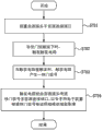
Fig. 9 utilizes the containment vessel 1 of the utility model first to fourth embodiment and the image pickup method flow chart of hand-hold electronic device 50.
As shown in Figure 9, utilize the aforementioned image pickup method that is installed in the hand-hold electronic device 50 of containment vessel 1 to comprise:
Step S701: during to containment vessel 1, plant source of sound joint 30 is in source of sound connectivity port 51 in installing hand-hold electronic device 50.
Step S702: when shutter release button 20 is pressed, trigger circuits for triggering 40.
Step S703: when circuits for triggering 40 were triggered, circuits for triggering 40 produced a shutter signal.
Step S704: circuits for triggering 40 transmit shutter signal to source of sound connectivity port 51 via source of sound joint 30, drive camera module 52 pick-up images with hand electronic device 50 according to shutter signal.
So, hand-hold electronic device 50 can detect the user and wishes to use the camera function of hand-hold electronic device 50 or take pictures.
In one embodiment, when hand-hold electronic device 50 receives shutter signal under exposal model, hand-hold electronic device 50 will drive camera module 52 pick-up images; When hand-hold electronic device 50 receives shutter signal under a non-exposal model, hand-hold electronic device 50 will switch to exposal model.That is to say that the user presses shutter release button 20 and the shutter signal that produces can order about hand-hold electronic device 50 and enters exposal model by non-exposal model, perhaps, can order about hand-hold electronic device 50 and take pictures.
In certain embodiments, the 3rd embodiment as described above, containment vessel 1 can comprise modular converter 41, so that shutter signal is converted to triggering signal, and transmits triggering signals to hand-hold electronic device 50 via source of sound joint 30 and source of sound connectivity port 51.Whereby, hand-hold electronic device 50 can drive camera module 52 pick-up images according to triggering signal, or enters exposal model by non-exposal model.
In certain embodiments, containment vessel 1 also can comprise aforesaid operating key 15.Similar to step S704 to abovementioned steps S702, when operating key 15 is pressed, trigger aforementioned circuits for triggering 40.When circuits for triggering 40 were triggered, circuits for triggering 40 produced control signal, and controlled signal to source of sound connectivity port 51 via 30 transmission of source of sound joint, produced interrupt events with hand electronic device 50.
When hand-hold electronic device 50 detects interrupt event in exposal model, will finish exposal model and enter the non-exposal model of corresponding interrupt event.For example, when the operating key 15 of corresponding browsing photo on the containment vessel 1 when hand-hold electronic device 50 is pressed in exposal model, hand-hold electronic device 50 enters the interrupt event of browsing photo with generation, and then enters the browsing photo pattern.Therefore, after the user has taken photo by preceding method, can inspect the photo of shooting immediately.
In this, be example though aforementioned operating key 15 with corresponding browsing photo triggers interrupt events, embodiment of the present utility model is non-as limit, and interrupt event also can non-ly be produced by corresponding operating key 15.For example, when hand-hold electronic device 50 was mobile phone, interrupt event can be the conversation requirement.
In certain embodiments, when the operating key 15 of correspondence focusing or convergent-divergent is pressed, circuits for triggering 40 will be triggered.When circuits for triggering 40 were triggered, circuits for triggering 40 produced a control signal.Then, circuits for triggering 40 can transmit via source of sound joint 30 and control signal to source of sound connectivity port 51, with a kind of action in hand electronic device 50 corresponding control signals execution focusing and the convergent-divergent.In this, though operating key 15 is focused with correspondence or is scaled the example explanation, embodiment of the present utility model is non-as limit.Operating key 15 also can be other function key of camera, as ISO setting, white balance setting, menu directionkeys etc.
In certain embodiments, hand-hold electronic device 50 can produce sound source signal in non-exposal model.And hand-hold electronic device 50 can transmit sound source signal to containment vessel 1 via source of sound connectivity port 51 and source of sound joint 30.Then, containment vessel 1 can sounding module 42 conversion sound source signals be sound wave.
When the source of sound connectivity port 51 of hand-hold electronic device 50 is connected with source of sound joint 30 usually, as desire output sound source signal, even hand-hold electronic device 50 has the audio output unit as loudspeaker, also can be by 51 outputs of source of sound connectivity port.Therefore; when hand-hold electronic device 50 meets the interrupt event of incoming call or desire broadcast music etc.; sound source signal can export source of sound joint 30 to via source of sound connectivity port 51, is sent to loud speaker 421 by source of sound joint 30 again, and the loud speaker 421 that so gets final product self-insurance protective case 1 is sounded.Whereby, the user need not pull down the sound that containment vessel 1 can be listened to the diaphone source signal, as caller dialogue or listen to music.
In sum, according to the containment vessel 1 of tool shutter structure of the present utility model, the person of being easy to use can finish shooting by pressing shutter release button 20 when gripping containment vessel 1.Because shutter release button 20 is positioned at the outside of housing 10, the user can press shutter release button 20 easily, and need not take by the screen that touches hand-hold electronic device 50.Moreover, when gripping containment vessel 1, the user controls the mode of shooting as camera, thus be available for users to firmly grip, and the experience of continuity camera.In addition, by in containment vessel 1 loud speaker 421 being set, the person of being easy to use need not remove the audio that containment vessel 1 can be heard the output of hand-hold electronic device 50.
Certainly; the utility model also can have other various embodiments; under the situation that does not deviate from the utility model spirit and essence thereof; those of ordinary skill in the art can make various corresponding changes and distortion according to the utility model, but these corresponding changes and distortion all should belong to the protection range of the utility model claim.
Claims (10)
1. the containment vessel of a tool shutter structure is handed electronic installation in order to be installed in one, and this hand-hold electronic device comprises a source of sound connectivity port and a camera module, it is characterized in that, this containment vessel comprises:
One housing comprises an accommodation space, this hand-hold electronic device of this holding space for holding;
One shutter release button is positioned on this housing the side with respect to this accommodation space;
One source of sound joint is positioned on this housing the side adjacent to this accommodation space, when this hand-hold electronic device is installed in this accommodation space, is engaged with each other with this source of sound connectivity port and signal is connected; And
One circuits for triggering are electrically connected between this shutter release button and this source of sound joint, when this shutter release button is pressed, transmit a shutter signal to this camera module via this source of sound connectivity port of this source of sound joint and this hand-hold electronic device.
2. the containment vessel of tool shutter structure according to claim 1 is characterized in that, wherein this housing has a bottom wall portion and from the extended side wall portion of the periphery of this bottom wall portion, to form this accommodation space by this bottom wall portion and this side wall portion.
3. the containment vessel of tool shutter structure according to claim 2 is characterized in that, wherein this side wall portion has a breach, and this breach is corresponding to a side of this bottom wall portion.
4. the containment vessel of tool shutter structure according to claim 3 is characterized in that, wherein this source of sound joint is positioned on this side wall portion and with respect to this breach.
5. the containment vessel of tool shutter structure according to claim 2; it is characterized in that; wherein this hand-hold electronic device comprises to a back side of pasting this bottom wall portion; this camera module is positioned on this back side; this bottom wall portion comprises an open-work; with when this hand-hold electronic device is installed in this containment vessel, manifest this camera module.
6. the containment vessel of tool shutter structure according to claim 5 is characterized in that, wherein this shutter release button is positioned at an end of a first side wall of this side wall portion, and this open-work is positioned on this bottom wall portion the other end part corresponding to this first side wall.
7. the containment vessel of tool shutter structure according to claim 1; it is characterized in that; wherein these circuits for triggering comprise a modular converter; this modular converter is electrically connected between this shutter release button and this source of sound joint; so that this shutter signal is converted to a triggering signal, and export this triggering signal to this source of sound joint.
8. the containment vessel of tool shutter structure according to claim 1; it is characterized in that these circuits for triggering comprise a sounding module, be electrically connected on this source of sound joint; reception is by a sound source signal of this source of sound connectivity port output of this hand-hold electronic device, and to change this sound source signal be a sound wave.
9. the containment vessel of tool shutter structure according to claim 8 is characterized in that, wherein this sounding module comprises a loud speaker.
10. the containment vessel of tool shutter structure according to claim 1; it is characterized in that; more comprise at least one operating key; be positioned on this housing the side with respect to this accommodation space; this operating key is electrically connected at this source of sound joint; when this shutter release button is pressed, transmit one via this source of sound joint and this source of sound connectivity port and control signal to this hand-hold electronic device, wherein this at least one operating key and this shutter release button form a coding type switches set.
Applications Claiming Priority (2)
| Application Number | Priority Date | Filing Date | Title |
|---|---|---|---|
| TW101219870U TWM452661U (en) | 2012-10-15 | 2012-10-15 | Protective cover with shutter structure |
| TW101219870 | 2012-10-15 |
Publications (1)
| Publication Number | Publication Date |
|---|---|
| CN203057211U true CN203057211U (en) | 2013-07-10 |
Family
ID=48740125
Family Applications (2)
| Application Number | Title | Priority Date | Filing Date |
|---|---|---|---|
| CN201210495149.2A Pending CN103731519A (en) | 2012-10-15 | 2012-11-28 | Protective shell with shutter structure and shooting method thereof |
| CN2012206405968U Expired - Fee Related CN203057211U (en) | 2012-10-15 | 2012-11-28 | Protective shell with shutter structure |
Family Applications Before (1)
| Application Number | Title | Priority Date | Filing Date |
|---|---|---|---|
| CN201210495149.2A Pending CN103731519A (en) | 2012-10-15 | 2012-11-28 | Protective shell with shutter structure and shooting method thereof |
Country Status (5)
| Country | Link |
|---|---|
| US (1) | US20140104491A1 (en) |
| JP (1) | JP3187341U (en) |
| CN (2) | CN103731519A (en) |
| DE (1) | DE202013103089U1 (en) |
| TW (1) | TWM452661U (en) |
Cited By (1)
| Publication number | Priority date | Publication date | Assignee | Title |
|---|---|---|---|---|
| CN103731519A (en) * | 2012-10-15 | 2014-04-16 | 大阪京科技(深圳)有限公司 | Protective shell with shutter structure and shooting method thereof |
Families Citing this family (11)
| Publication number | Priority date | Publication date | Assignee | Title |
|---|---|---|---|---|
| US9716524B2 (en) * | 2013-08-08 | 2017-07-25 | Ramin Rostami | System, apparatus and method for generic electronic device power module and case formation |
| CN104917854B (en) * | 2014-03-12 | 2017-08-25 | 纬创资通股份有限公司 | Signal transmitting apparatus |
| CN104918432A (en) * | 2014-03-12 | 2015-09-16 | 富士康(昆山)电脑接插件有限公司 | Protective housing and assembly thereof |
| JP6541278B2 (en) * | 2014-08-15 | 2019-07-10 | ホアウェイ・テクノロジーズ・カンパニー・リミテッド | Portable terminal holder |
| US10032137B2 (en) | 2015-08-31 | 2018-07-24 | Avaya Inc. | Communication systems for multi-source robot control |
| US9509361B1 (en) | 2015-11-05 | 2016-11-29 | Blackberry Limited | Camera-based accessory classification |
| GB201603379D0 (en) * | 2016-02-26 | 2016-04-13 | Henry Sean | Photography accessory for a portable electronic device |
| KR20170112497A (en) * | 2016-03-31 | 2017-10-12 | 엘지전자 주식회사 | Mobile terminal and method for controlling the same |
| JP6101884B1 (en) * | 2016-05-18 | 2017-03-22 | まさみ 仁頃 | Exterior products to be attached to mobile terminals |
| CN208707745U (en) * | 2018-06-29 | 2019-04-05 | 深圳市大疆创新科技有限公司 | Picture shooting assembly and attachment |
| WO2023083075A1 (en) * | 2021-11-09 | 2023-05-19 | 影石创新科技股份有限公司 | Camera protection frame and modular camera |
Family Cites Families (7)
| Publication number | Priority date | Publication date | Assignee | Title |
|---|---|---|---|---|
| JP2005310685A (en) * | 2004-04-26 | 2005-11-04 | Casio Comput Co Ltd | Push-button structure and waterproof case |
| US20070103582A1 (en) * | 2005-11-09 | 2007-05-10 | Q-Mark Technology Corp. | PSP video conversion device |
| JP5144424B2 (en) * | 2007-10-25 | 2013-02-13 | キヤノン株式会社 | Imaging apparatus and information processing method |
| US8374495B2 (en) * | 2009-06-04 | 2013-02-12 | Sanwa Technologies Limited | User-configurable waterproof camera case |
| US8230126B2 (en) * | 2009-10-27 | 2012-07-24 | Fairchild Semiconductor Corporation | Camera shutter control through a USB port or audio/video port |
| US8244299B1 (en) * | 2011-03-16 | 2012-08-14 | John Bishop | Grip attachment for a mobile phone |
| TWM452661U (en) | 2012-10-15 | 2013-05-11 | Ozaki Int Co Ltd | Protective cover with shutter structure |
-
2012
- 2012-10-15 TW TW101219870U patent/TWM452661U/en not_active IP Right Cessation
- 2012-11-28 CN CN201210495149.2A patent/CN103731519A/en active Pending
- 2012-11-28 CN CN2012206405968U patent/CN203057211U/en not_active Expired - Fee Related
-
2013
- 2013-07-11 US US13/939,532 patent/US20140104491A1/en not_active Abandoned
- 2013-07-11 DE DE202013103089U patent/DE202013103089U1/en not_active Expired - Lifetime
- 2013-09-10 JP JP2013005263U patent/JP3187341U/en not_active Expired - Fee Related
Cited By (1)
| Publication number | Priority date | Publication date | Assignee | Title |
|---|---|---|---|---|
| CN103731519A (en) * | 2012-10-15 | 2014-04-16 | 大阪京科技(深圳)有限公司 | Protective shell with shutter structure and shooting method thereof |
Also Published As
| Publication number | Publication date |
|---|---|
| DE202013103089U1 (en) | 2013-09-26 |
| TWM452661U (en) | 2013-05-11 |
| JP3187341U (en) | 2013-11-21 |
| CN103731519A (en) | 2014-04-16 |
| US20140104491A1 (en) | 2014-04-17 |
Similar Documents
| Publication | Publication Date | Title |
|---|---|---|
| CN203057211U (en) | Protective shell with shutter structure | |
| CN201319596Y (en) | Interface device between handheld media player and electronic equipment | |
| CN103702252B (en) | For the system of the one or more functions of control electronics | |
| US9451352B2 (en) | Unlocking apparatus and method using ear-micro headset in terminal | |
| CN107426444B (en) | mobile terminal | |
| CN107222233A (en) | Mobile communication equipment | |
| CN202424796U (en) | Protective shell applicable to IPHONE4 or IPHONE4S mobile phone | |
| CN2870067Y (en) | Multifunction combined display | |
| TW201025742A (en) | Portable electric apparatus and jack connection method therefor | |
| CN111935593B (en) | Recording pen and recording control method | |
| CN106451824A (en) | Bluetooth earphone charging method, Bluetooth earphone charging device and Bluetooth earphone | |
| CN108513218A (en) | Voice-frequency channel control method and electronic equipment | |
| CN209860622U (en) | Wireless earphone charging device and wireless earphone | |
| CN109360577B (en) | Method, apparatus, and storage medium for processing audio | |
| WO2020042491A9 (en) | Headphone far-field interaction method, headphone far-field interaction accessory, and wireless headphones | |
| WO2018227434A1 (en) | Electronic device | |
| CN213339682U (en) | Sound recording pen | |
| CN108683800A (en) | Mobile terminal, method for detecting position and Related product | |
| CN212086427U (en) | High sampling rate bluetooth voice transmission system | |
| CN111556406B (en) | Audio processing method, audio processing device and earphone | |
| CN106303786A (en) | A kind of terminal of integrated detachable earphone | |
| JP2012191611A (en) | Communication device and changeover method | |
| CN206136218U (en) | Terminal of earphone can be dismantled in integration | |
| CN211720719U (en) | Rectangular ear-hanging type touch wireless Bluetooth headset | |
| CN211702366U (en) | Bluetooth headset with K sings function |
Legal Events
| Date | Code | Title | Description |
|---|---|---|---|
| C14 | Grant of patent or utility model | ||
| GR01 | Patent grant | ||
| CF01 | Termination of patent right due to non-payment of annual fee |
Granted publication date: 20130710 Termination date: 20151128 |