CN203055652U - Combined type mutual inductor - Google Patents
Combined type mutual inductor Download PDFInfo
- Publication number
- CN203055652U CN203055652U CN 201320034702 CN201320034702U CN203055652U CN 203055652 U CN203055652 U CN 203055652U CN 201320034702 CN201320034702 CN 201320034702 CN 201320034702 U CN201320034702 U CN 201320034702U CN 203055652 U CN203055652 U CN 203055652U
- Authority
- CN
- China
- Prior art keywords
- voltage
- transformer
- secondary coil
- primary winding
- electric current
- Prior art date
- Legal status (The legal status is an assumption and is not a legal conclusion. Google has not performed a legal analysis and makes no representation as to the accuracy of the status listed.)
- Expired - Fee Related
Links
Images

Abstract
A combined type mutual inductor comprises a first combined mutual inductor and a second combined mutual inductor, wherein the structure of the first combined mutual inductor is identical to the structure of the second combined inductor. The first combined mutual inductor comprises a first current transformer portion and a first voltage transformer portion. Two first wiring boards of the first current transformer are respectively connected with a first current primary coil through a connecting board, a first current secondary coil is sleeved on the first current primary coil, and the first current secondary coil is connected with a first current outgoing terminal through wires. One end of the first voltage primary coil of the first voltage transformer portion is connected with any connecting board of the first current transformer portion, and the other end of the first voltage primary coil is connected with the outgoing terminal of the upper end of a tower column through wires. A first voltage secondary coil is sleeved on the first voltage primary coil, and the first voltage secondary coil is connected with a first voltage outgoing terminal through wires. The combined type mutual inductor is stable in performance, and large in metering range.
Description
Technical field
The utility model belongs to the combined instrument transformer field, and particularly a kind of combined instrument transformer is used for exchanging 50Hz, and in the rated voltage 10kV circuit, voltage supplied, electric current, electric energy measurement and relaying protection are used.
Background technology
Form and be contained in instrument transformer in the same shell by current transformer and voltage transformer.The iron core of the voltage segment of present normally used combined instrument transformer has iron loss big usually, the shortcoming of unstable properties.And the current transformer part exists measures range little usually, the shortcoming that certainty of measurement is low.
The utility model content
Content of the present utility model provides a kind of combined instrument transformer, and the stable performance of this instrument transformer, measures range are big.
The technical scheme that adopts is:
A kind of combined instrument transformer comprises first combination transformer, second combination transformer and insulation shell.
Its technical essential is:
First combination transformer comprises first current transformer part and the first voltage transformer part.First current transformer part can be positioned at first voltage transformer part top.
First current transformer partly comprises two first terminal blocks and the first electric current primary winding.
Two first terminal blocks are connected with the first electric current primary winding with second connecting plate by first connecting plate respectively, are arranged with the first electric current secondary coil on the first electric current primary winding, and the first electric current secondary coil is connected with the first electric current outlet terminal by lead.Be provided with current ferric core in the first electric current secondary coil.
First voltage transformer partly comprises the first voltage primary winding and the first voltage secondary coil.
The first voltage primary winding, one end is connected by first connecting plate or second connecting plate of lead with first current transformer part, and the other end of the first voltage primary winding is connected by the outlet terminal of lead with the king-post upper end.
Be arranged with the first voltage secondary coil on the first voltage primary winding, the first voltage secondary coil is connected with the first voltage outlet terminal by lead.Be provided with the voltage iron core in the first voltage secondary coil.
Second combination transformer comprises second current transformer part and the second voltage transformer part.Second current transformer part can be positioned at second voltage transformer part top.
Second current transformer partly comprises two second terminal blocks and the second electric current primary winding.
Two second terminal blocks are connected with the second electric current primary winding with the 4th connecting plate by the 3rd connecting plate respectively, are arranged with the second electric current secondary coil on the second electric current primary winding, and the second electric current secondary coil is connected with the second electric current outlet terminal by lead.Be provided with current ferric core in the second electric current secondary coil.
Second voltage transformer partly comprises the second voltage primary winding and the second voltage secondary coil.
The second voltage primary winding, one end is connected by the 3rd connecting plate or the 4th connecting plate of lead with second current transformer part, and the other end of the second voltage primary winding is connected by the outlet terminal of lead with the king-post upper end.
Be arranged with the second voltage secondary coil on the second voltage primary winding, the second voltage secondary coil is connected with the second voltage outlet terminal by lead.Be provided with the voltage iron core in the second voltage secondary coil.
First combination transformer and second combination transformer all are positioned at insulation shell, there is the king-post that is wholely set at the insulation shell middle part, first combination transformer and second combination transformer can symmetry be arranged at the king-post both sides, and first combination transformer is identical with the second combination transformer structure.
Insulation shell is fixed on the base, and insulation shell is the epoxy resin housing, and king-post is the epoxy resin king-post.
The insulation shell outer surface can be provided with silicone rubber housings, and silicone rubber housings top can be wholely set a plurality of full skirts.Anti-electricity-theft protective cover can be installed in the silicone rubber housings bottom.
The potential winding iron core adopts C sections core, forms through the annealing of reeling, and iron loss is little, magnetic is close low, and product data are good, stable performance, and iron core is by lead and ground connection inserts reliable ground.The current coil iron core then adopts the amorphous alloy iron core of high-magnetodensity, and accuracy class is higher than the 0.2S level.FS is low for the instrument safety coefficient, and the coil electric power is little, and current loading is big, and maximum can reach 3 grades of loads, has enlarged measures range, for the automatic wide load metering of batch meter provides reliable assurance.Product has adopted silicon rubber insulation, waterproof, antiultraviolet, anti-resin season cracking, and it is clear to identify.Profile is umbrella skirt construction, to raising surface creepage distance, and the dielectric strength height, stable and reliable for performance.Small product size dwindles 13%, and weight has reduced 5kg, the convenient installation.
The voltage primary winding of the part of voltage transformer can be connected with in the middle of two connecting plates of corresponding current instrument transformer part any one and gets final product.When indoor use, can not use silicone rubber housings, when outdoor, can add the silicone rubber housings protection.
Its advantage is:
This instrument transformer is applicable to rated frequency 50HZ, does meritorious, reactive energy metering in the outdoor AC electric power system of rated voltage 10KV, and stable performance, measures range are big.
Description of drawings
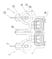
Fig. 1 is structural representation of the present utility model.
Fig. 2 is the end view of Fig. 1.
Embodiment
A kind of combined instrument transformer comprises first combination transformer 1, second combination transformer 2 and insulation shell 17.
First combination transformer 1 comprises first current transformer part and the first voltage transformer part.First current transformer partly is positioned at first voltage transformer part top.
First current transformer partly comprises two first terminal blocks 3 and the first electric current primary winding 4.
Two first terminal blocks 3 are connected with the first electric current primary winding 4 with second connecting plate by first connecting plate 5 respectively, being arranged with the first electric current secondary coil, 6, the first electric current secondary coils 6 on the first electric current primary winding 4 is connected with the first electric current outlet terminal 7 by lead.Be provided with current ferric core in the first electric current secondary coil 6.
First voltage transformer partly comprises the first voltage primary winding 8 and the first voltage secondary coil 9.
The first voltage primary winding, 8 one ends are connected by first connecting plate 5 of lead with first current transformer part, and the other end of the first voltage primary winding 8 is connected by the outlet terminal of lead with king-post 10 upper ends.
Being arranged with the first voltage secondary coil, 9, the first voltage secondary coils 9 on the first voltage primary winding 8 is connected with the first voltage outlet terminal 11 by lead.Be provided with the voltage iron core in the first voltage secondary coil 9, the voltage iron core is two symmetrically arranged C sections cores.
Second current transformer partly comprises two second terminal blocks 12 and the second electric current primary winding 13.
Two second terminal blocks 12 are connected with the second electric current primary winding 13 with the 4th connecting plate by the 3rd connecting plate respectively, being arranged with the second electric current secondary coil, 14, the second electric current secondary coils 14 on the second electric current primary winding 13 is connected with the second electric current outlet terminal by lead.Be provided with current ferric core in the second electric current secondary coil 14.
Second voltage transformer partly comprises the second voltage primary winding 15 and the second voltage secondary coil 16.
The second voltage primary winding, 15 1 ends are connected by the 3rd connecting plate of lead with second current transformer part, and the other end of the second voltage primary winding 15 is connected by the outlet terminal of lead with king-post 10 upper ends.
Being arranged with the second voltage secondary coil, 16, the second voltage secondary coils 16 on the second voltage primary winding 15 is connected with the second voltage outlet terminal by lead.Be provided with the voltage iron core in the second voltage secondary coil 16, the voltage iron core is two symmetrically arranged C sections cores.
First combination transformer 1 and second combination transformer 2 all are cast in the insulation shell 17, there is the king-post 10 that is wholely set at insulation shell 17 middle parts, first combination transformer 1 and second combination transformer, 2 symmetries be arranged at king-post 10 both sides, and first combination transformer 1 is identical with second combination transformer, 2 structures.
Anti-electricity-theft protective cover 19 can be installed in silicone rubber housings 20 bottoms, and described anti-electricity-theft protective cover 19 is known technology, so repeated description not.
Embodiment 1 is substantially the same manner as Example 2, and its difference is that the first voltage primary winding 8 is not connected with first connecting plate, 5 leads, but the first voltage primary winding 8 is connected with the second connecting plate lead.
The second voltage primary winding 15 is not connected with the 3rd connecting plate lead, but the second voltage primary winding 15 is connected with the 4th connecting plate lead.
Claims (3)
1. a combined instrument transformer comprises first combination transformer (1), second combination transformer (2) and insulation shell (17); It is characterized in that:
First combination transformer (1) comprises first current transformer part and the first voltage transformer part;
First current transformer partly comprises two first terminal blocks (3) and the first electric current primary winding (4);
Two first terminal blocks (3) are connected with the first electric current primary winding (4) with second connecting plate by first connecting plate (5) respectively, be arranged with the first electric current secondary coil (6) on the first electric current primary winding (4), the first electric current secondary coil (6) is connected with the first electric current outlet terminal (7) by lead; Be provided with current ferric core in the first electric current secondary coil (6);
First voltage transformer partly comprises the first voltage primary winding (8) and the first voltage secondary coil (9);
The first voltage primary winding (8) one ends are connected by first connecting plate (5) or second connecting plate of lead with first current transformer part, and the other end of the first voltage primary winding (8) is connected by the outlet terminal of lead with king-post (10) upper end;
Be arranged with the first voltage secondary coil (9) on the first voltage primary winding (8), the first voltage secondary coil (9) is connected with the first voltage outlet terminal (11) by lead; Be provided with the voltage iron core in the first voltage secondary coil (9);
Second combination transformer (2) comprises second current transformer part and the second voltage transformer part;
Second current transformer partly comprises two second terminal blocks (12) and the second electric current primary winding (13);
Two second terminal blocks (12) are connected with the second electric current primary winding (13) with the 4th connecting plate by the 3rd connecting plate respectively, be arranged with the second electric current secondary coil (14) on the second electric current primary winding (13), the second electric current secondary coil (14) is connected with the second electric current outlet terminal by lead; Be provided with current ferric core in the second electric current secondary coil (14);
Second voltage transformer partly comprises the second voltage primary winding (15) and the second voltage secondary coil (16);
The second voltage primary winding (15) one ends are connected by the 3rd connecting plate or the 4th connecting plate of lead with second current transformer part, and the other end of the second voltage primary winding (15) is connected by the outlet terminal of lead with king-post (10) upper end;
Be arranged with the second voltage secondary coil (16) on the second voltage primary winding (15), the second voltage secondary coil (16) is connected with the second voltage outlet terminal by lead; Be provided with the voltage iron core in the second voltage secondary coil (16);
First combination transformer (1) and second combination transformer (2) all are positioned at insulation shell (17), there is the king-post (10) that is wholely set at insulation shell (17) middle part, first combination transformer (1) and second combination transformer (2) symmetry be arranged at king-post (10) both sides, and first combination transformer (1) is identical with second combination transformer (2) structure;
Insulation shell (17) is fixed on the base (18), and insulation shell (17) is the epoxy resin housing, and king-post (10) is the epoxy resin king-post.
2. a kind of combined instrument transformer according to claim 1, it is characterized in that: described insulation shell (17) outer surface is provided with silicone rubber housings (20), and silicone rubber housings (20) top has been wholely set a plurality of full skirts.
3. a kind of combined instrument transformer according to claim 2, it is characterized in that: anti-electricity-theft protective cover (19) is installed in silicone rubber housings (20) bottom.
Priority Applications (1)
| Application Number | Priority Date | Filing Date | Title |
|---|---|---|---|
| CN 201320034702 CN203055652U (en) | 2013-01-23 | 2013-01-23 | Combined type mutual inductor |
Applications Claiming Priority (1)
| Application Number | Priority Date | Filing Date | Title |
|---|---|---|---|
| CN 201320034702 CN203055652U (en) | 2013-01-23 | 2013-01-23 | Combined type mutual inductor |
Publications (1)
| Publication Number | Publication Date |
|---|---|
| CN203055652U true CN203055652U (en) | 2013-07-10 |
Family
ID=48738580
Family Applications (1)
| Application Number | Title | Priority Date | Filing Date |
|---|---|---|---|
| CN 201320034702 Expired - Fee Related CN203055652U (en) | 2013-01-23 | 2013-01-23 | Combined type mutual inductor |
Country Status (1)
| Country | Link |
|---|---|
| CN (1) | CN203055652U (en) |
Cited By (2)
| Publication number | Priority date | Publication date | Assignee | Title |
|---|---|---|---|---|
| CN104240929A (en) * | 2014-09-18 | 2014-12-24 | 江苏科兴电器有限公司 | Single-phase pouring type combination measuring dry transformer |
| CN105261471A (en) * | 2013-08-02 | 2016-01-20 | 胡小青 | Multifunctional high-voltage transformer |
-
2013
- 2013-01-23 CN CN 201320034702 patent/CN203055652U/en not_active Expired - Fee Related
Cited By (5)
| Publication number | Priority date | Publication date | Assignee | Title |
|---|---|---|---|---|
| CN105261471A (en) * | 2013-08-02 | 2016-01-20 | 胡小青 | Multifunctional high-voltage transformer |
| CN105261470A (en) * | 2013-08-02 | 2016-01-20 | 胡小青 | High-voltage transformer |
| CN105261471B (en) * | 2013-08-02 | 2019-01-29 | 乐清市华尊电气有限公司 | Multifunctional high-voltage transformer |
| CN105261470B (en) * | 2013-08-02 | 2019-01-29 | 乐清市华尊电气有限公司 | High-voltage mutual inductor |
| CN104240929A (en) * | 2014-09-18 | 2014-12-24 | 江苏科兴电器有限公司 | Single-phase pouring type combination measuring dry transformer |
Similar Documents
| Publication | Publication Date | Title |
|---|---|---|
| CN204332669U (en) | High-voltage electric-energy meter integral combined transformer | |
| CN203799857U (en) | Low-partial-discharge high-capacity post type current transformer | |
| CN203055652U (en) | Combined type mutual inductor | |
| CN206460865U (en) | A kind of Integral three-phase current transformer | |
| CN203551621U (en) | High-voltage dry-type metering box with three-phase four-wire system | |
| CN203562291U (en) | Totally-closed current transformer | |
| CN2909477Y (en) | Current transformer | |
| CN203799859U (en) | Outdoor bus type current transformer | |
| CN203799858U (en) | Dry type current transformer high in no-load voltage ratio and capacity | |
| CN203799852U (en) | Indoor voltage transformer | |
| CN202282238U (en) | Indoor current transformer | |
| CN202307496U (en) | Electronic high-voltage current transformer | |
| CN202084414U (en) | Combined-type zero sequence current mutual inductor | |
| CN101930838A (en) | Electronic type voltage transformer | |
| CN216250270U (en) | Three-phase four-wire combined transformer for outdoor 10kV line metering | |
| CN202282239U (en) | Indoor current transformer | |
| CN206421907U (en) | A kind of combination transformer voltage cell machine body structure | |
| CN203746653U (en) | Novel current mutual inductor | |
| CN214099316U (en) | Integrated outdoor 10kV current and voltage combined transformer | |
| CN205104355U (en) | Current inducer | |
| CN205230796U (en) | Voltage transformer | |
| CN204558235U (en) | A kind of resistance mode of resonance voltage transformer | |
| CN214099387U (en) | V-shaped wiring combined transformer for outdoor 35kV metering | |
| CN211045255U (en) | High-capacity and high-precision zero-sequence current transformer | |
| CN104240929A (en) | Single-phase pouring type combination measuring dry transformer |
Legal Events
| Date | Code | Title | Description |
|---|---|---|---|
| C14 | Grant of patent or utility model | ||
| GR01 | Patent grant | ||
| C56 | Change in the name or address of the patentee | ||
| CP01 | Change in the name or title of a patent holder |
Address after: 116200, Liaoning City, Dalian province Pulandian Taiping Office Home Industrial Zone Patentee after: Sino Canton electric appliance Limited by Share Ltd Address before: 116200, Liaoning City, Dalian province Pulandian Taiping Office Home Industrial Zone Patentee before: Dalian Zhongguang Instrument Transformer Co., Ltd. |
|
| CF01 | Termination of patent right due to non-payment of annual fee | ||
| CF01 | Termination of patent right due to non-payment of annual fee |
Granted publication date: 20130710 Termination date: 20210123 |