CN203044173U - Novel shallow groove dual-impeller flotation machine - Google Patents
Novel shallow groove dual-impeller flotation machine Download PDFInfo
- Publication number
- CN203044173U CN203044173U CN 201220738329 CN201220738329U CN203044173U CN 203044173 U CN203044173 U CN 203044173U CN 201220738329 CN201220738329 CN 201220738329 CN 201220738329 U CN201220738329 U CN 201220738329U CN 203044173 U CN203044173 U CN 203044173U
- Authority
- CN
- China
- Prior art keywords
- impeller
- cell body
- stirring
- novel shallow
- novel
- Prior art date
- Legal status (The legal status is an assumption and is not a legal conclusion. Google has not performed a legal analysis and makes no representation as to the accuracy of the status listed.)
- Withdrawn - After Issue
Links
Images


Landscapes
- Paper (AREA)
Abstract
The utility model relates to the field of coal flotation equipment, in particular to a novel shallow groove dual-impeller flotation machine. The novel shallow groove dual-impeller flotation machine solves the problems that a mechanical agitation floatation machine is insufficient in stand-alone machine processing ability due to the volume limitation of a groove body, low in flotation efficiency and large in production line capital construction investment. The novel shallow groove dual-impeller flotation machine is composed of a groove body, a stirring mechanism, a false bottom steady flow plate, a bubble blow mechanism and the like. The stirring mechanism comprises a stirring shaft, a stirring impeller is fixedly arranged on the stirring shaft, a stator which is of a split-type structure is arranged at the periphery side of the stirring impeller, the stirring impeller and the stator are located on the upper side of the false bottom steady flow plate, the stirring impeller is fixed on the middle section of the stirring shaft, an impulse impeller is fixedly arranged at the bottom end of the stirring shaft and located on the lower side of the false bottom steady flow plate, and a flow guide barrel is arranged on the periphery side of the impulse impeller. According to the novel shallow groove dual-impeller flotation machine, a novel pulp feeding mode is provided, the circulation state of pulp inside a groove is enabled to be smooth, power consumption and agent consumption are reduced, and high efficiency separation of floating mineral grains and recycle of the floating mineral grains are achieved.
Description
Technical field
The utility model relates to coal floatation equipment field, particularly a kind of novel shallow slot bilobed wheel flotation device.
Background technology
Flotation is the main method of fine-grained mineral separation, and nearly all mineral can adopt floatation to separate from ore, can process simultaneously and handle secondary resource and non-mineral resource.
It is the inexorable trend of China's coal preparation industry development that coal preparation plant's scale maximization, equipment enlarging, technology are oversimplified.Though recent years, flotation device was obtained certain progress aspect maximization,, the unit maximum processing capability can only satisfy the requirement of the selected ability (being equivalent to 1,500,000 t/a coal preparation plants) of 300t/h raw coal.Average size according to the former coal throughput 800t/h of developed country is calculated, and single groove volume of flotation device should reach 60m
3, and the present maximum air suction type agitation impeller flotator of China has only 28m
3, still can not satisfy the needs that large-scale efficient coal separation is produced.The development trend of coal preparation plant's maximization, high efficiency, energy-conservationization, automation presses for large-scale floatation equipment.
Flotation device is because the intensification of cell body and the increase of stirring region often exist partial inflation inhomogeneous, and mineral grain is difficult to fully mix with bubble, exists problems such as tangible dead band in the circulation loop of ore pulp, has strengthened the flotation power consumption, has reduced flotation efficiency.Therefore, existing flotator structure form is optimized solves this a series of difficult problems.
Summary of the invention
The utility model because the cell body volume limits to the unit disposal ability deficiency that causes, the problem that flotation efficiency is low, production line capital construction has high input, provides a kind of novel shallow slot bilobed wheel flotation device in order to solve the mechanical agitation flotation device.
In order to address the above problem, the utility model is taked following technical scheme: novel shallow slot bilobed wheel flotation device, comprise partly composition such as cell body, rabbling mechanism, stabilier of the false end and foam scraping machine, described rabbling mechanism comprises shaft, agitator arm is fixedly arranged on the shaft, the all sides of agitator arm are provided with the stator of split-type structural, agitator arm, stator are positioned at stabilier upside of the false end, described agitator arm is fixed in the shaft stage casing, the shaft bottom is impulse impeller fixedly, impulse impeller is positioned at stabilier downside of the false end, and all sides of impulse impeller are provided with guide shell.The utility model is the bilobed wheel rabbling mechanism, and agitator arm provides enough aeration quantitys, and impulse impeller promotes bottom ore pulp circulation.The moment of torsion of drive motors being exported by transmission device passes to shaft, shaft drives agitator arm and impulse impeller rotates synchronously, the impulse impeller that is positioned at the shaft bottom is boosted to the suction inlet of agitator arm vertically by the ore pulp that rotation will enter under the stabilier of the false end, for agitator arm continues to provide ore pulp, accelerate the shuttling movement of cell body bottom ore pulp, greatly degree has reduced the depositional phenomenon of flotation device cell body bottom ore pulp.
Guide shell is made of several and the radiation flow deflector of angle at 45 radially, and guide shell is positioned at the center of cell body base plate, and the guide shell top connects stabilier of the false end.The radiation flow deflector has 12.Guide shell has supported the bilobed wheel rabbling mechanism and has strengthened the structural stability of stabilier of the false end.The combination of guide shell and impulse impeller reduces the ore pulp resistance of motion, and the motion ore pulp in the impulse impeller working region is played the effect of guiding and current stabilization, reaches continual and steady cell body bottom and advances pan feeding, the efficient of raising ore pulp mineralising.
Described cell body section is rectangle, and the cell body open top is inverse, and the cell body left side is provided with the chats case that Open Side Down, and the right side is provided with the chats case that opening makes progress, and some cell bodies connect successively by the chats case, and both sides are provided with 45 ° of hypotenuses before and after the cell body bottom.Cell body is the rectangular cross section of herringbone opening, can give full play to the volume advantage, for ore particle and bubble hit, adhere to enough spaces are provided, forms froth bed stably easily.The cell body both sides are provided with 45 ° of hypotenuses, are conducive to rough grain and assemble to the groove center stirring region, avoid the cell body two bottom sides ore pulp deposition to occur.Be connected by immersion chats case between each groove, make the ore pulp reverse movement of mineral laden bubble and discharge, improved separation accuracy.
The degree of depth in cell body cross section is 0.6 with the ratio of width.Cell body adopts shallow slot, stirs power consumption to reduce.
Shaft is provided with air-breathing sleeve pipe, and air-breathing sleeve pipe upper end connects air, and air-breathing sleeve pipe lower end is communicated with upper chamber and the lower floor chamber of agitator arm.Under the agitator arm centrifugal action, form negative pressuren zone, suck extraneous air by air-breathing sleeve pipe warp beam sleeve tube, enter in the upper and lower layer of the agitator arm chamber, under blade and liquid stream shear action, form bubble, and the bottom suction inlet that passes through agitator arm sucks ore pulp, enter in the agitator arm lower floor chamber, inhaled air is mixed with ore pulp, throw away along stabilier of the false end, rotate synchronously by the bottom impulse impeller simultaneously, the ore pulp circulation of increasing cell body bottom, propelling movement ore pulp enter and mix the zone, avoid the bottom ore pulp to deposit effectively.
Compared with prior art, the beneficial effects of the utility model are: a kind of ore pulp enter material way of novelty is provided, has made the interior ore pulp recurrent state of groove more smooth, power consumption and medicine consumption reduce, and realize the product of the efficient sorting of float particle and recovery.
Description of drawings
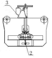
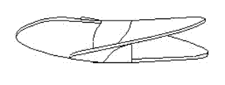
Fig. 1 is the utility model complete machine front view;
Fig. 2 is the utility model complete machine side view;
Fig. 3 is the utility model complete machine vertical view;
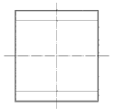
Fig. 4 is the front view of the utility model cell body;
Fig. 5 is the side view of the utility model cell body;
Fig. 6 is the vertical view of the utility model cell body;
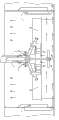
Fig. 7 is the schematic diagram of the utility model rabbling mechanism;
Fig. 8 is groove fluid movement view;
Fig. 9 is the guide shell front view;
Figure 10 is the guide shell vertical view;
Figure 11 is the guide shell schematic diagram;
Figure 12 is the impulse impeller front view;
Figure 13 is the impulse impeller vertical view;
Figure 14 is the impulse impeller schematic diagram;
1-cell body among the figure, 2-rabbling mechanism, 2.1-drive motors, 2.2-transmission device, the air-breathing sleeve pipe of 2.3-, 2.4-shaft, 2.5-stator cover plate, 2.6-stator, 2.7-agitator arm, 2.8-impulse impeller, the 3-support, stabilier of the false end of 4-, 5-foam scraping machine, 6-chats case.
The specific embodiment
By reference to the accompanying drawings the specific embodiment of the present utility model is described further.
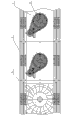
Novel shallow slot bilobed wheel flotation device described in the utility model mainly is in series by a plurality of cell body 1 as shown in Figure 1, 2, 3, be communicated with by the chats case between each groove, the center of cell body is provided with the bilobed wheel rabbling mechanism, foam scraping machine is arranged in the both sides of bilobed wheel rabbling mechanism, is positioned at more than the cell body liquid level.
1, cell body
Cell body is rectangular cross section, shown in Fig. 4,5,6, has the sufficient advantage of volume, for ore particle and bubble hit, adhere to enough spaces are provided.
The cell body both sides are provided with shown in 45 ° of hypotenuses, are conducive to rough grain and assemble to the groove center stirring region, avoid the cell body two bottom sides ore pulp deposition to occur.
The cell body open top has increased the notch area for falling " eight " word Mechanical Builds, has reduced the height of complete machine, forms froth bed stably easily.
Cell body adopts shallow slot, and namely the cell body section depth is 0.45~0.65 with the ratio of width, and this product design is 0.6, stirs power consumption to reduce.
2, rabbling mechanism
As shown in Figure 7, rabbling mechanism is by the driving motor supplies power that is installed on the support, belt driver is given shaft with transmission of power, shaft is fixed in the center of cell body by bearing block, agitator arm is by stirring locking device, be fixed in the stage casing of shaft, with to be positioned at stator on the stabilier of the false end and cover plate concentric and keep certain interval.Agitator arm is double-deck umbrella shape impeller, in its rotary course at a high speed, produce powerful negative pressure in stator interior, can suck air from the outside by air-breathing sleeve pipe, the ore pulp that will enter simultaneously under the stabilier of the false end sucks, ore pulp and air are mixed fully and cut, make ore particle and bubble incorporation, on float to the upper strata liquid level.
Impulse impeller is fixed in the stirring the tip of the axis by the axle head locking device, in the process of itself and agitator arm rotation synchronously, blade by impulse impeller is pushed the ore pulp of cell body bottom the suction inlet of agitator arm to vertically, has pan feeding concurrently and promotes the effect of ore pulp circulation.
Guide shell is arranged at the center of cell body base plate, is installed on the periphery of following, the impulse impeller of stabilier of the false end, has supported the bilobed wheel rabbling mechanism and has strengthened the structural stability of stabilier of the false end.Guide shell is formed with the radiation flow deflector of angle at 45 radially by 12, and this version reduces the ore pulp resistance of motion, the motion ore pulp in the impulse impeller working region is played the effect of guiding and current stabilization.
3, foam scraping machine
In the foam scraping machine, scraper plate is fixed in to be scraped on the bubble axle, and its radius of gyration can be adjusted by the slotted hole on the clamp, reductor drives scraper plate around scraping the center rotation of bubble axle, when mineral laden bubble rises to remittance foam layer, discharged by scraper plate, realize that the cleaned coal froth bed separates with ore pulp.
The moment of torsion that the present invention exports drive motors by belt driver passes to shaft, shaft drives agitator arm and impulse impeller rotates synchronously, the impulse impeller that is positioned at the shaft bottom is boosted to the suction inlet of agitator arm vertically by the ore pulp that rotates under the stabilier of the false end that will enter, for stirring region continues to provide ore pulp, accelerated the shuttling movement of cell body bottom ore pulp, can make not entered by the coal grain of mineralising to mix the district.Greatly degree has reduced the depositional phenomenon of flotation device cell body bottom ore pulp.The agitator arm that is positioned at the shaft stage casing forms negative pressuren zone by being rotated under the centrifugal action, suck extraneous air by air-breathing sleeve pipe warp beam sleeve tube, under blade and liquid stream shear action, form bubble, and suck ore pulp by the bottom suction inlet of agitator arm, enter in the agitator arm lower floor chamber, inhaled air is fully mixed with ore pulp, be distributed in the cell body cross section equably, and move up and enter the Disengagement zone, enrichment forms the cleaned coal froth bed, discharged by foam scraping machine, finish whole assorting room.
Claims (7)
1. novel shallow slot bilobed wheel flotation device, comprise cell body, rabbling mechanism, stabilier of the false end and foam scraping machine, described rabbling mechanism comprises shaft, agitator arm is fixedly arranged on the shaft, the all sides of agitator arm are provided with split type stator, agitator arm, stator are positioned at stabilier center upside of the false end, it is characterized in that: described agitator arm is fixed in the shaft stage casing, the shaft bottom is impulse impeller fixedly, impulse impeller is positioned at stabilier center downside of the false end, and all sides of impulse impeller are provided with guide shell.
2. novel shallow slot bilobed wheel flotation device according to claim 1 is characterized in that: guide shell is made of several and radiation flow deflectors that angle radially at 45 distributes, and guide shell is positioned at the center of cell body base plate, and guide shell top connects stabilier of the false end.
3. novel shallow slot bilobed wheel flotation device according to claim 2, it is characterized in that: guide shell arranges 12 of radiation flow deflectors.
4. according to claim 1 or 2 or 3 described novel shallow slot bilobed wheel flotation devices, it is characterized in that: shaft is provided with air-breathing sleeve pipe, and air-breathing sleeve pipe upper end connects air, and air-breathing sleeve pipe lower end is communicated with upper chamber and the lower floor chamber of agitator arm.
5. novel shallow slot bilobed wheel flotation device according to claim 4, it is characterized in that: described cell body section is rectangle, and the cell body open top is inverse, and both sides are provided with 45 ° of chamferings before and after the cell body bottom.
6. novel shallow slot bilobed wheel flotation device according to claim 5, it is characterized in that: the degree of depth in cell body cross section is 0.45~0.65 with the ratio of width.
7. novel shallow slot bilobed wheel flotation device according to claim 6, it is characterized in that: the degree of depth in cell body cross section is 0.6 with the ratio of width.
Priority Applications (1)
| Application Number | Priority Date | Filing Date | Title |
|---|---|---|---|
| CN 201220738329 CN203044173U (en) | 2012-12-28 | 2012-12-28 | Novel shallow groove dual-impeller flotation machine |
Applications Claiming Priority (1)
| Application Number | Priority Date | Filing Date | Title |
|---|---|---|---|
| CN 201220738329 CN203044173U (en) | 2012-12-28 | 2012-12-28 | Novel shallow groove dual-impeller flotation machine |
Publications (1)
| Publication Number | Publication Date |
|---|---|
| CN203044173U true CN203044173U (en) | 2013-07-10 |
Family
ID=48727172
Family Applications (1)
| Application Number | Title | Priority Date | Filing Date |
|---|---|---|---|
| CN 201220738329 Withdrawn - After Issue CN203044173U (en) | 2012-12-28 | 2012-12-28 | Novel shallow groove dual-impeller flotation machine |
Country Status (1)
| Country | Link |
|---|---|
| CN (1) | CN203044173U (en) |
Cited By (4)
| Publication number | Priority date | Publication date | Assignee | Title |
|---|---|---|---|---|
| CN103041932A (en) * | 2012-12-28 | 2013-04-17 | 太原轨道交通装备有限责任公司 | Novel shallow-trough double-impeller flotation machine |
| CN105268561A (en) * | 2015-10-31 | 2016-01-27 | 湖州佳思机械科技有限公司 | Mineral flotation machine |
| CN108452953A (en) * | 2018-01-19 | 2018-08-28 | 武汉工程大学 | A kind of twin shaft double speed bilobed wheel flotation agitating device |
| CN113617538A (en) * | 2021-09-01 | 2021-11-09 | 西山煤电(集团)有限责任公司 | Jet type flotation machine for coal |
-
2012
- 2012-12-28 CN CN 201220738329 patent/CN203044173U/en not_active Withdrawn - After Issue
Cited By (6)
| Publication number | Priority date | Publication date | Assignee | Title |
|---|---|---|---|---|
| CN103041932A (en) * | 2012-12-28 | 2013-04-17 | 太原轨道交通装备有限责任公司 | Novel shallow-trough double-impeller flotation machine |
| CN103041932B (en) * | 2012-12-28 | 2015-05-06 | 太原轨道交通装备有限责任公司 | Novel shallow-trough double-impeller flotation machine |
| CN105268561A (en) * | 2015-10-31 | 2016-01-27 | 湖州佳思机械科技有限公司 | Mineral flotation machine |
| CN108452953A (en) * | 2018-01-19 | 2018-08-28 | 武汉工程大学 | A kind of twin shaft double speed bilobed wheel flotation agitating device |
| CN108452953B (en) * | 2018-01-19 | 2020-05-22 | 武汉工程大学 | Double-shaft double-speed double-impeller flotation stirring device |
| CN113617538A (en) * | 2021-09-01 | 2021-11-09 | 西山煤电(集团)有限责任公司 | Jet type flotation machine for coal |
Similar Documents
| Publication | Publication Date | Title |
|---|---|---|
| CN103041932B (en) | Novel shallow-trough double-impeller flotation machine | |
| CN107971143B (en) | A kind of bilobed wheel mechanical stirring self-suction type flotation machine and method for floating | |
| CN209005951U (en) | It is a kind of to realize highly purified quartz sand flotation machine | |
| CN102240608B (en) | Coal ash flotation separation equipment provided with reflection cone gas dispersing device | |
| CN204523264U (en) | A kind of mining flotation device | |
| CN106493000B (en) | A kind of bottom driving type lab flotation cell | |
| CN203044173U (en) | Novel shallow groove dual-impeller flotation machine | |
| CN109939838B (en) | Forced circulation rapid flotation separation device and method | |
| CN202137055U (en) | Oxidized ore flotation machine | |
| CN103657876A (en) | Energy-saving efficient mineral flotation device and method | |
| CN202137054U (en) | Machine-column combined strengthened high-efficiency floatation column | |
| CN102284371A (en) | Column combined reinforced high-efficiency flotation method and flotation equipment thereof | |
| CN108435440A (en) | A kind of grind floats integrated apparatus and working method | |
| CN209034566U (en) | A kind of efficient quartz sand flotation machine | |
| CN208414021U (en) | Big flux spiral-flow type algae water separation device | |
| CN205288717U (en) | High flotation device of high -efficient flotation precision | |
| CN210522812U (en) | Novel flotation device for mineral separation of splashproof ore deposit | |
| CN107051752A (en) | Flotation device | |
| CN202741248U (en) | Jetting and stirring flotation machine | |
| CN112934484B (en) | Fly ash flotation separation equipment with turbulent flow type air dispersing device | |
| CN102921558B (en) | Injection, agitation and aspiration combined flotation machine | |
| CN112246447A (en) | Over-and-under type flotation device is used in graphite production | |
| CN210434689U (en) | Forced circulation quick flotation separation device | |
| CN203972154U (en) | A kind of boosted suction jet agitation formula flotation device | |
| CN105772228A (en) | Rotary jet mixing low-energy consumption flotation equipment driven by utilizing ore pulp |
Legal Events
| Date | Code | Title | Description |
|---|---|---|---|
| C14 | Grant of patent or utility model | ||
| GR01 | Patent grant | ||
| AV01 | Patent right actively abandoned |
Granted publication date: 20130710 Effective date of abandoning: 20150506 |
|
| RGAV | Abandon patent right to avoid regrant |