CN203028473U - Atomizing toilet brush - Google Patents
Atomizing toilet brush Download PDFInfo
- Publication number
- CN203028473U CN203028473U CN 201220663761 CN201220663761U CN203028473U CN 203028473 U CN203028473 U CN 203028473U CN 201220663761 CN201220663761 CN 201220663761 CN 201220663761 U CN201220663761 U CN 201220663761U CN 203028473 U CN203028473 U CN 203028473U
- Authority
- CN
- China
- Prior art keywords
- rod
- button
- handle
- push rod
- brush
- Prior art date
- Legal status (The legal status is an assumption and is not a legal conclusion. Google has not performed a legal analysis and makes no representation as to the accuracy of the status listed.)
- Expired - Fee Related
Links
Images


Abstract
The utility model discloses an atomizing toilet brush which comprises a rod body, a brush head, a pump body, a button, an ejection rod, a suction tube, a handle and a sealing ring. The rod body is provided with a pump body seat and a transfusion hole. The brush head is provided with a connector seat and a spraying hole. A pump pressing ring is arranged on the pump body. A hinged shaft is arranged on the button. The ejection rod is provided with a clamp opening, a liquid suction opening and a clamping ring. The handle is provided with a button shaft seat and an ejection rod hole. The brush head is connected with a connector of the rod body in an inserting mode through the connector seat. The pump body is arranged on the pump body seat. The clamping opening of the ejection rod is connected with the pump pressing ring of the pump body in a clamping mode. The button is hinged with the button shaft seat of the handle. The handle is sleeved at an opening end of the rod body. According to the atomizing toilet brush, scrubbing solution is internally placed in the rod body and sprayed when being used so that the atomizing toilet brush has the advantages that a procedure is simplified, direct contact between the scrubbing solution and the hands is avoided, structure is simple and use is convenient.
Description
Technical field
The utility model relates to the brush of daily cleaning articles for use technical field, especially a kind of spraying toilet brush.
Background technology
Cleaning toilet is the affairs of everyday facing in the daily life, and prior art is being implemented to clean in the clear process of toilet, need clean with rag or cleaning brush at the surface of toilet spraying cleaning solution, rinses well with clear water again.The problem that exists is, in the process of scrubbing, the spraying cleaning solution is cleaned with cleaning brush more in advance, causes complex procedures, and careless slightly, both hands touch cleaning solution, also will cause skin injury.
The utility model content
The purpose of this utility model is a kind of spraying toilet brush that provides at the deficiencies in the prior art, the utility model is built in cleaning solution in the body of rod, with using with spray, has simplified operation, avoid cleaning solution directly to contact with hand, had advantage simple in structure, easy to use.
The concrete technical scheme that realizes the utility model purpose is:
A kind of spraying toilet brush, its characteristics comprise the body of rod, brush, the pump housing, button, push rod, suction pipe, handle and sealing ring, the described body of rod is the pipe fitting that an end opening, the other end are provided with joint, joint is provided with pump housing seat and infusion hole, and brush is provided with plinth, and plinth is provided with spray orifice, the pump housing is provided with the pump pressure ring, button is provided with hinge, and an end of push rod is provided with bayonet socket and liquid sucting port, the other end is provided with snap ring, and handle is provided with button axle bed and jogger hole; Described brush is pegged graft through the joint of plinth and the body of rod, and infusion hole docks with spray orifice, the pump housing, push rod are located in the body of rod, and the pump housing is located on the pump housing seat, the bayonet socket of push rod is connected on the pump pressure ring of the pump housing, and button is hinged through the button axle bed of hinge and handle, and taper knob is contained in the openend of the body of rod, and jogger hole and button that push rod passes handle touch, suction pipe is inserted on the liquid sucting port of push rod, and sealing ring is located on the push rod, and between the jogger hole of snap ring and handle.
The utility model is built in cleaning solution in the body of rod, with using with spray, has simplified operation, has avoided cleaning solution directly to contact with hand, has advantage simple in structure, easy to use.
Description of drawings
Fig. 1 is structural representation of the present utility model;
Fig. 2 is the structural representation of the utility model body of rod;
Fig. 3 is the structural representation of the utility model brush;
Fig. 4 is the structural representation of the utility model button;
Fig. 5 is the structural representation of the utility model push rod;
Fig. 6 is the structural representation of the utility model handle.
The specific embodiment
Consult Fig. 1, the utility model comprises the body of rod 1, brush 2, the pump housing 3, button 4, push rod 5, suction pipe 6, handle 7 and sealing ring 8, and the described pump housing 3 is provided with pump pressure ring 31; Described brush 2 is pegged graft through plinth 21 and the joint 11 of the body of rod 1, and infusion hole 13 docks with spray orifice 22, the pump housing 3, push rod 5 are located in the body of rod 1, and the pump housing 3 is located on the pump housing seat 12, the bayonet socket 51 of push rod 5 is connected on the pump pressure ring 31 of the pump housing 3, button 4 is hinged with the button axle bed 71 of handle 7 through hinge 41, handle 7 is sleeved on the openend of the body of rod 1, and the jogger hole 72 that push rod 5 passes handle 7 touches with button 4, suction pipe 6 is inserted on the liquid sucting port 52 of push rod 5, sealing ring 8 is located on the push rod 5, and between the jogger hole 72 of snap ring 53 and handle 7.
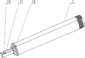
Consult Fig. 2, the described body of rod 1 is the pipe fitting that an end opening, the other end are provided with joint 11, and joint 11 is provided with pump housing seat 12 and infusion hole 13.
Consult Fig. 3, described brush 2 is provided with plinth 21, and plinth 21 is provided with spray orifice 22.
Consult Fig. 4, described button 4 is provided with hinge 41.
Consult Fig. 5, an end of described push rod 5 is provided with bayonet socket 51 and liquid sucting port 52, the other end is provided with snap ring 53.
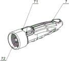
Consult Fig. 6, described handle 7 is provided with button axle bed 71 and jogger hole 72.
The utility model is to use like this:
A) add cleaning solution
The openend of handle 7 from the body of rod 1 unloaded, the openend of cleaning solution by the body of rod 1 added in the pipe fitting of the body of rod 1, handle 7 is sleeved on the openend of the body of rod 1, the jogger hole 72 that makes push rod 5 pass handle 7 touches with button 4, at this moment, sealing ring 8 is sealed in cleaning solution in the pipe fitting of the body of rod 1 between the jogger hole 72 of snap ring 53 and handle 7, and the cleaning solution adding finishes.
B) application of the present utility model
Grasp handle 7, brush 2 is placed on the surface that desire is cleaned in the toilet, when in needs are given toilet, spraying cleaning solution, press button 4 with thumb, make button axle bed 71 swings of button 4 thorny handles 7, at this moment, because push rod 5 passes the jogger hole 72 of handle 7 and touches with button 4, the bayonet socket 51 of push rod 5 is connected on the pump pressure ring 31 of the pump housing 3, so, when push rod 5 in the body of rod 1 during axial float, the pump pressure ring 31 of the bayonet socket 51 compressing pump housings 3 of push rod 5, the pump housing 3 work are sprayed onto toilet bowl interior with cleaning solution from the infusion hole 13 of the body of rod 1 joint 11 and the spray orifice 22 of brush 2, mobile brush 2, with brushing with spray, finish the utility model to the scouring of toilet, rinse well with clear water more at last, namely finish cleaning.
Press button 4 repeatedly with thumb, when push rod 5 makes progress play under the reaction force of the pump housing 3, form negative pressure between the bayonet socket 51 of push rod 5 and the pump pressure ring 31 of the pump housing 3, cleaning solution in the body of rod 1 enters in the liquid sucting port 52 of push rod 5 through suction pipe 6 absorption, in order to spraying from brush 2 again, press button 4 repeatedly, can implement intermittently to spray repeatedly the function of cleaning solution.
Claims (1)
- One kind the spraying toilet brush, it is characterized in that it comprises the body of rod (1), brush (2), the pump housing (3), button (4), push rod (5), suction pipe (6), handle (7) and sealing ring (8), the described body of rod (1) is an end opening, the other end is provided with the pipe fitting of joint (11), joint (11) is provided with pump housing seat (12) and infusion hole (13), brush (2) is provided with plinth (21), plinth (21) is provided with spray orifice (22), the pump housing (3) is provided with pump pressure ring (31), button (4) is provided with hinge (41), one end of push rod (5) is provided with bayonet socket (51) and liquid sucting port (52), the other end is provided with snap ring (53), and handle (7) is provided with button axle bed (71) and jogger hole (72); Described brush (2) is pegged graft through plinth (21) and the joint (11) of the body of rod (1), and infusion hole (13) docks with spray orifice (22), the pump housing (3), push rod (5) is located in the body of rod (1), and the pump housing (3) is located on the pump housing seat (12), the bayonet socket (51) of push rod (5) is connected on the pump pressure ring (31) of the pump housing (3), button (4) is hinged with the button axle bed (71) of handle (7) through hinge (41), handle (7) is sleeved on the openend of the body of rod (1), and the jogger hole (72) that push rod (5) passes handle (7) touches with button (4), suction pipe (6) is inserted on the liquid sucting port (52) of push rod (5), sealing ring (8) is located on the push rod (5), and is positioned between the jogger hole (72) of snap ring (53) and handle (7).
Priority Applications (1)
| Application Number | Priority Date | Filing Date | Title |
|---|---|---|---|
| CN 201220663761 CN203028473U (en) | 2012-12-06 | 2012-12-06 | Atomizing toilet brush |
Applications Claiming Priority (1)
| Application Number | Priority Date | Filing Date | Title |
|---|---|---|---|
| CN 201220663761 CN203028473U (en) | 2012-12-06 | 2012-12-06 | Atomizing toilet brush |
Publications (1)
| Publication Number | Publication Date |
|---|---|
| CN203028473U true CN203028473U (en) | 2013-07-03 |
Family
ID=48680629
Family Applications (1)
| Application Number | Title | Priority Date | Filing Date |
|---|---|---|---|
| CN 201220663761 Expired - Fee Related CN203028473U (en) | 2012-12-06 | 2012-12-06 | Atomizing toilet brush |
Country Status (1)
| Country | Link |
|---|---|
| CN (1) | CN203028473U (en) |
Cited By (1)
| Publication number | Priority date | Publication date | Assignee | Title |
|---|---|---|---|---|
| CN108741609A (en) * | 2018-06-11 | 2018-11-06 | 林展韬 | A kind of detergent of closet hair brush structure |
-
2012
- 2012-12-06 CN CN 201220663761 patent/CN203028473U/en not_active Expired - Fee Related
Cited By (1)
| Publication number | Priority date | Publication date | Assignee | Title |
|---|---|---|---|---|
| CN108741609A (en) * | 2018-06-11 | 2018-11-06 | 林展韬 | A kind of detergent of closet hair brush structure |
Similar Documents
| Publication | Publication Date | Title |
|---|---|---|
| CN203028473U (en) | Atomizing toilet brush | |
| CN203457968U (en) | Multipurpose cleaner | |
| CN203290836U (en) | Novel mist spray toilet brush | |
| CN202477621U (en) | Washing brush in-built sprayer | |
| CN212186339U (en) | Liquid-spraying toilet brush | |
| CN210783340U (en) | Multi-purpose self-spraying water cleaning brush | |
| CN201290870Y (en) | Medical wounded surface cleaner | |
| CN210871355U (en) | Dry-wet dual-purpose degerming rag | |
| CN103520746A (en) | Medical sterilizing device | |
| CN210696486U (en) | Pot brush with novel structure and capable of discharging liquid | |
| CN211703797U (en) | Non-wet hand washing brush | |
| CN209058250U (en) | A kind of multifunctional sanitation cleaning apparatus | |
| CN103462556A (en) | Using method of handheld cleaning tool capable of vibrating and spraying water | |
| CN209883353U (en) | Multifunctional toothbrush | |
| CN201899060U (en) | Cleaning brush | |
| CN220458810U (en) | Washing article bottle | |
| CN220403403U (en) | Multifunctional medical instrument cleaning brush | |
| CN200939100Y (en) | Automatic water spraying floor scruber | |
| CN2722708Y (en) | Brush for kitchen | |
| CN206355012U (en) | A kind of novel dish mop | |
| CN201899575U (en) | Portable tooth cleaner | |
| CN201595797U (en) | Multifunctional mop | |
| CN2507393Y (en) | Sanitary wiper contg. cleaning agent | |
| CN201157573Y (en) | Female genitalia cleaner | |
| CN202800566U (en) | Brush |
Legal Events
| Date | Code | Title | Description |
|---|---|---|---|
| C14 | Grant of patent or utility model | ||
| GR01 | Patent grant | ||
| CF01 | Termination of patent right due to non-payment of annual fee |
Granted publication date: 20130703 Termination date: 20171206 |
|
| CF01 | Termination of patent right due to non-payment of annual fee |