CN203027105U - Automobile generator carbon brush installation structure - Google Patents
Automobile generator carbon brush installation structure Download PDFInfo
- Publication number
- CN203027105U CN203027105U CN 201220255738 CN201220255738U CN203027105U CN 203027105 U CN203027105 U CN 203027105U CN 201220255738 CN201220255738 CN 201220255738 CN 201220255738 U CN201220255738 U CN 201220255738U CN 203027105 U CN203027105 U CN 203027105U
- Authority
- CN
- China
- Prior art keywords
- carbon brush
- carbon
- installation structure
- automobile generator
- welded
- Prior art date
- Legal status (The legal status is an assumption and is not a legal conclusion. Google has not performed a legal analysis and makes no representation as to the accuracy of the status listed.)
- Expired - Fee Related
Links
Images

Landscapes
- Motor Or Generator Current Collectors (AREA)
Abstract
The utility model relates to an automobile generator carbon brush installation structure. The automobile generator carbon brush installation structure comprises a collecting ring, a carbon brush holder, carbon brushes, springs and carbon brush wires. The automobile generator carbon brush installation structure is characterized in that the carbon brushes are placed in the carbon brush holder, the tail ends of the carbon brushes are welded with the carbon brush wires, each carbon brush wire is sleeved with a spring, the upper top end of each spring is opposite to an insulating plate which is installed on the carbon brush holder, each carbon brush wire passes through the insulating plate and welded with a connector sheet, a sleeving hole is formed in each connector sheet, the sleeving hole is sleeved onto a connector lug which is fixed on the carbon brush holder, and the connector sheets and the connector lug are welded and connected together. The automobile generator carbon brush installation structure is characterized in that the size of the sleeving hole in the connector sheet is larger than the contour dimension of the connector lug. The automobile generator carbon brush installation structure of the utility model has the following advantages that not only the automobile generator carbon brush installation structure can be used to solve the problem that the original carbon brush installation process is complex and improve the installation efficiency, and but also the automobile generator carbon brush installation structure can be used to ensure that the lengths of portions of the carbon brushes which are in contact with the collecting ring are the same and the carbon brushees can be in contact with the generator collecting ring effectively and ensure the continuously output current of the generator.
Description
Technical field
The utility model relates to a kind of automobile current generator carbon brush mounting structure.
Background technology
The mounting structure of the carbon brush in present existing automobile current generator is, first overlap upper spring 12 on the wire 11 of carbon brush 10 welding, then put into together in brush rocker and carbon brush groove 13, put again insulation board 14 in the above, then the brush lead termination is welded on (see figure 1) on 1.5*1.5 joint 15 on brush holder with the flatiron soldering.very loaded down with trivial details of this process, efficient is very low, and after the carbon brush sleeve upper spring, be contained in frame carbon brush groove unfixing, after putting insulation board, because between carbon brush and insulation board, spring is arranged, the elasticity of spring makes the brush lead termination can not as one man be welded on the joint of 1.5*1.5 on brush holder, the length of the other end of carbon brush contact automobile current generator collector ring 16 is inconsistent so, if because two carbon brush slightly have gap when welding, two carbon brush size of touching the automobile current generator collector ring is inconsistent, thereby cause the output voltage of generator unstable, if produce between contact in the situation of large resistance, carbon brush and automobile current generator collector ring can generate heat, the bad phenomenon such as cause that generator burns.Therefore demand urgently the mounting structure of the carbon brush in existing automobile current generator is improved.
Summary of the invention
The purpose of this utility model is the existing the problems referred to above of mounting structure that solve the carbon brush in automobile current generator in prior art, and a kind of automobile current generator carbon brush mounting structure is provided.A kind of automobile current generator carbon brush mounting structure of the utility model design, comprise collector ring, carbon brush holder, carbon brush, spring, brush lead, it is characterized in that: be placed with carbon brush in carbon brush holder, the end of carbon brush is welded with brush lead, on brush lead, cover has spring, the upper top of spring is relative with the insulation board on being arranged on carbon brush holder, brush lead passes insulation board and tab welding, offer sleeve joint hole on tab, sleeve joint hole is socketed on the connector lug that is fixed on carbon brush holder, and tab and connector lug are welded to connect.It is characterized in that: the sleeve joint hole on tab is greater than the overall dimension of connector lug.The utility model has the advantages that both to have solved the loaded down with trivial details of original carbon brush mounting process, improved the efficient of installing, guaranteed that carbon brush touches the length of collector ring consistent, can effectively touch collector ring of generator, guarantee generator continuous output current in a steady stream.
Description of drawings
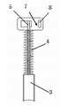
Accompanying drawing 1 is the structural representation of prior art, and Fig. 2 is structural representation of the present utility model, Fig. 3 by tab of the present utility model and the structural representation of connection brush lead.
Embodiment
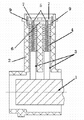
Figure comprises collector ring 1, carbon brush holder 2, carbon brush 3, spring 4, brush lead 5, it is characterized in that: be placed with carbon brush in carbon brush holder, the end of carbon brush is welded with brush lead, on brush lead, cover has spring, the upper top of spring is relative with insulation board 6 on being arranged on carbon brush holder, and brush lead passes insulation board and tab 7 welding, offers sleeve joint hole 8 on tab 7, sleeve joint hole is socketed on the connector lug 9 that is fixed on carbon brush holder, and tab 7 is welded to connect with connector lug 9.It is characterized in that: the sleeve joint hole on tab is greater than the overall dimension of connector lug.
during concrete fitting operation, first weld brush lead on carbon brush, then overlap upper spring, the outer end point of brush lead is welded on tab, subsequently in the whole mounting groove of putting carbon brush holder into of the carbon brush that point is welded, then plug insulation board, and this tab is passed insulation board, that sleeve joint hole (size 1.6*1.6 millimeter) sky on tab is pierced on the joint of (size 1.5*1.5 millimeter) on connector lug on carbon brush holder, at last tab and connector lug soldering are lived, owing to can relatively keeping like this carbon brush after last installation and the position of collector ring, generally can not produce the error of large-size, therefore can make carbon brush and collector ring reliable contact under the holding of spring, guarantee generator continuous output current in a steady stream.
Claims (2)
1. automobile current generator carbon brush mounting structure, comprise collector ring, carbon brush holder, carbon brush, spring, brush lead, it is characterized in that: be placed with carbon brush in carbon brush holder, the end of carbon brush is welded with brush lead, on brush lead, cover has spring, the upper top of spring is relative with the insulation board on being arranged on carbon brush holder, brush lead passes insulation board and tab welding, offer sleeve joint hole on tab, sleeve joint hole is socketed on the connector lug that is fixed on carbon brush holder, and tab and connector lug are welded to connect.
2. by a kind of automobile current generator carbon brush mounting structure claimed in claim 1, it is characterized in that: the sleeve joint hole on tab is greater than the overall dimension of connector lug.
Priority Applications (1)
| Application Number | Priority Date | Filing Date | Title |
|---|---|---|---|
| CN 201220255738 CN203027105U (en) | 2012-06-01 | 2012-06-01 | Automobile generator carbon brush installation structure |
Applications Claiming Priority (1)
| Application Number | Priority Date | Filing Date | Title |
|---|---|---|---|
| CN 201220255738 CN203027105U (en) | 2012-06-01 | 2012-06-01 | Automobile generator carbon brush installation structure |
Publications (1)
| Publication Number | Publication Date |
|---|---|
| CN203027105U true CN203027105U (en) | 2013-06-26 |
Family
ID=48651050
Family Applications (1)
| Application Number | Title | Priority Date | Filing Date |
|---|---|---|---|
| CN 201220255738 Expired - Fee Related CN203027105U (en) | 2012-06-01 | 2012-06-01 | Automobile generator carbon brush installation structure |
Country Status (1)
| Country | Link |
|---|---|
| CN (1) | CN203027105U (en) |
Cited By (1)
| Publication number | Priority date | Publication date | Assignee | Title |
|---|---|---|---|---|
| CN106849460A (en) * | 2016-12-30 | 2017-06-13 | 江苏云意电气股份有限公司 | A kind of carbon brush protects fixed structure and preparation method |
-
2012
- 2012-06-01 CN CN 201220255738 patent/CN203027105U/en not_active Expired - Fee Related
Cited By (2)
| Publication number | Priority date | Publication date | Assignee | Title |
|---|---|---|---|---|
| CN106849460A (en) * | 2016-12-30 | 2017-06-13 | 江苏云意电气股份有限公司 | A kind of carbon brush protects fixed structure and preparation method |
| CN106849460B (en) * | 2016-12-30 | 2023-08-08 | 江苏云意电气股份有限公司 | Carbon brush protection fixing structure and manufacturing method |
Similar Documents
| Publication | Publication Date | Title |
|---|---|---|
| CN201758769U (en) | Electronic cigarette heating device | |
| CN203027105U (en) | Automobile generator carbon brush installation structure | |
| CN203135043U (en) | Conductive polar pole | |
| CN207068969U (en) | Battery protecting plate and supply unit | |
| CN202405074U (en) | Copper aluminium compression connection structure for reactor | |
| CN202549700U (en) | Miniaturized electric conduction structure | |
| CN201194305Y (en) | Rotary electricity conducting apparatus | |
| CN202473989U (en) | Improving diode connection structure photovoltaic junction box | |
| CN201298572Y (en) | Battery welded sheet with crossed holes | |
| CN205335462U (en) | Contact shell fragment reaches charger and adapter including this contact shell fragment | |
| CN204231260U (en) | There is the electric machine controller of phase wire-connecting device | |
| CN204441681U (en) | Torsion spring structure hung by high voltage direct current motor carbon brush | |
| CN204088834U (en) | Multipurpose burner | |
| CN204930383U (en) | Electronic cigarette and battery component thereof | |
| CN204481435U (en) | Bus wire clamp | |
| CN103208692A (en) | Conductive pole column | |
| CN211406296U (en) | Connection structure of flexible heating film leading-out wire | |
| CN203119679U (en) | Supporting device for assembling capacitance and inductance components | |
| CN209057022U (en) | A kind of lug plate connection structure starting motor | |
| CN203607580U (en) | Internet access and USB interface connector | |
| CN205826698U (en) | A kind of voltage acquisition terminal and comprise the structural member of this voltage acquisition terminal | |
| CN201113165Y (en) | Commutator | |
| CN202362329U (en) | Electric energy meter | |
| CN201994441U (en) | Connector connected with battery | |
| CN203895612U (en) | Vehicle connecting line |
Legal Events
| Date | Code | Title | Description |
|---|---|---|---|
| C14 | Grant of patent or utility model | ||
| GR01 | Patent grant | ||
| CF01 | Termination of patent right due to non-payment of annual fee | ||
| CF01 | Termination of patent right due to non-payment of annual fee |
Granted publication date: 20130626 Termination date: 20190601 |